Download code from GitHub
Introducing the Vehicle Electrical/Electronic Architecture
The vehicle Electrical/Electronic (E/E) architecture refers to the set of electronic components, electrical wire harnesses, networking technologies, and software applications that coalesce to manage a diverse suite of vehicle functions tasked with controlling the vehicle and user experience.
While the combination of software and electronics has revolutionized how vehicle features are designed and deployed, it gradually produced a rich attack surface that made vehicles vulnerable to cyber threats. Therefore, understanding the fundamental concepts of the E/E architecture is a prerequisite to analyzing vehicle security. To help provide the necessary background, first, we will explore the various hardware platforms supported in the electronic control unit (ECU) and the corresponding reference software architectures. Next, we will examine how ECUs can be grouped into domains (which are distinct functional subsystems that have specific responsibilities) along with the networking technologies needed for their communication. With the ECUs and network layers defined, we will turn our attention to the sensors and actuators that enable the vehicle to sense the environment and react to it. Finally, we will put all these components together in the different vehicle architecture topologies while showing current and future trends in this area. Following this hierarchical approach should help us gain perspective on how the vehicle can be attacked.
As we dive through the E/E architecture layers, we will pose a series of questions in the form of discussion points to help you explore threats against your vehicle components. A brief answer list will be provided at the end of this chapter. The next few chapters will offer deeper insights into these discussion points as we navigate the cybersecurity threat landscape.
Note that this chapter does not attempt to offer a comprehensive list of every possible E/E architecture and component, but rather focuses on the aspects that are most relevant to vehicle cybersecurity. If you are well acquainted with vehicle E/E architecture concepts, this chapter can be considered a review to set the stage for cybersecurity analysis.
In this chapter, we will cover the following main topics:
- Overview of the basic building blocks of the E/E architecture
- Electronic control units
- ECU domains
- Exploring the in-vehicle network
- Sensors and actuators
- Exploring the vehicle architecture types
Overview of the basic building blocks of the E/E architecture
Before we explore the multiple layers of the E/E architecture, we must start with ECUs. These ECUs are grouped into ECU domains, which are interconnected by a suite of in-vehicle network communication channels. The ECUs are further connected to sensors and actuators through a mixture of hardwired and network-based connections. The combination of ECUs, sensors, actuators, and network channels can be arranged in different configurations, giving rise to several variants of the vehicle E/E architecture. Figure 1.1 shows a simplified example of an E/E architecture:

Figure 1.1 – Simplified vehicle architecture view
Our first stop will be ECUs.
Electronic control units
ECUs are at the heart of the E/E architecture and consist primarily of the processing elements and electronic components necessary to perform one or more vehicle functions, such as steering, information display, seat control, and more. In the simplified view of Figure 1.1, we can see seven ECUs interconnected through the vehicle network (for demonstration purposes only). One such ECU is the electronic braking control module (EBCM), which is responsible for active safety functions such as anti-lock braking systems (ABSs) and electronic stability control (ESC). Another ECU is the battery management system (BMS), which is commonly found in electric vehicles.
Figure 1.2 – Closed box view of an ECU
The electronic components of the ECU are housed in a sealed enclosure that is designed to withstand harsh environmental conditions such as heat, vibration, and electromagnetic interference. The black connector shown in Figure 1.2 enables the ECU to interface with the rest of the vehicle E/E architecture through a set of cables known as the wire harness. Mapping the pin out of the connector is the first step to determine which signals are relevant for cybersecurity. The power inputs, physical network bus lines, hard-wired sensor inputs, and actuation outputs are among the typical assets that are considered for protection against security threats.
If you were to crack open the ECU enclosure, as shown in Figure 1.3, you would find a PCB populated with various passive and active electronic components, such as relays, solenoids, resistors, capacitors, diodes, the power management integrated circuit (PMIC), network transceiver memory chips, and, most importantly, a microcontroller (MCU) or system on chip (SoC).
Figure 1.3 – Open box view of an ECU
Due to their power, cost, and timing performance constraints, most ECU types are driven by an MCU that realizes the vehicle functions through software running on one or more CPU cores embedded within the MCU.
SoCs, on the other hand, integrate several components into one chip to offer higher computation resources with larger memory and networking capabilities, making them well suited for applications such as infotainment and autonomous driving systems.
Discussion point 1
Can you think of any assets that are worth protecting once the PCB layout is exposed?
Answers to all discussion points are provided at the end of this chapter.
To answer the preceding question, let’s first dive a bit deeper into the hardware architecture of MCU-based ECUs before moving on to SoCs.
Looking at MCU-based ECUs
An MCU-based ECU executes software through one or more symmetric CPU cores that fetch code and data from the MCU’s internal flash memory. Code execution from the internal flash is a key requirement to meet the hard real-time constraints of these ECUs. Even when external flash memory is used, it is normally restricted to storing data such as images or audio files, as is the case with an instrument cluster ECU.
Figure 1.4 – A typical MCU block diagram
MCUs come in many variants, each tailored for a specific vehicle ECU application type. For example, an MCU for engine control will have many high-precision timer units, while an MCU for body control will have a large number of general-purpose input/output (I/O) pins. When analyzing the cybersecurity threats of a specific ECU, it is important to understand the different peripherals that are available as they may introduce a unique set of assets and attack surfaces. Figure 1.4 shows a block diagram for a typical 32 bit microcontroller with multiple peripherals and networking interfaces.
Looking back at Figure 1.3, we can start to explore the assets that can be probed for by an attacker who has possession of the ECU. For one, the MCU’s memory contents are an interesting target for exposure. This is where the ECU control software and calibration data are stored and therefore are of value at least to the ECU supplier, who may wish to protect their intellectual property against illegal access. Together with the vehicle’s original equipment manufacturer (OEM), they both want to prevent probers from discovering exploits that can be leveraged in more sophisticated attacks. However, since the memory is embedded inside the MCU, by having possession of the open ECU, an attacker cannot directly probe the memory contents. Instead, they will have to explore ways to leverage the on-chip debug features or serial flash programming interfaces to gain access to the memory’s contents.
Discussion point 2
Looking at the block diagram in Figure 1.4, can you guess what might be another asset that is of interest to an attacker who has possession of our ECU?
Looking at SoC-based ECUs
At first glance, the main difference between the SoC and MCU is the increased level of complexity and the diverse set of peripherals offered. For one, the SoC has a combination of CPU clusters that serve different use cases. The application CPUs feature multiple symmetric cores that target computationally intensive functions such as perception, path planning, and sensor fusion. On the other hand, the real-time CPUs feature multiple symmetric cores that target safety-critical functions such as fault monitoring and error reporting. In addition to the common network peripheral types of an MCU, we expect to see a higher number of network interfaces with higher bandwidth (for example, Ethernet 1 GB/10 GB links and PCIE). One significant difference with the MCU-based architecture is that code execution is out of DRAM as opposed to the embedded flash. Additionally, eMMC and QSPI flash interfaces are commonly used to support loading code and data from external storage devices. As is the case with the MCUs, SoCs come in different variants as they aim to serve specific vehicle use cases. For example, you will find that SoCs for ADAS applications are equipped with computer vision and deep learning accelerators, while SoCs for infotainment are equipped with video encoders/decoders for media streaming:
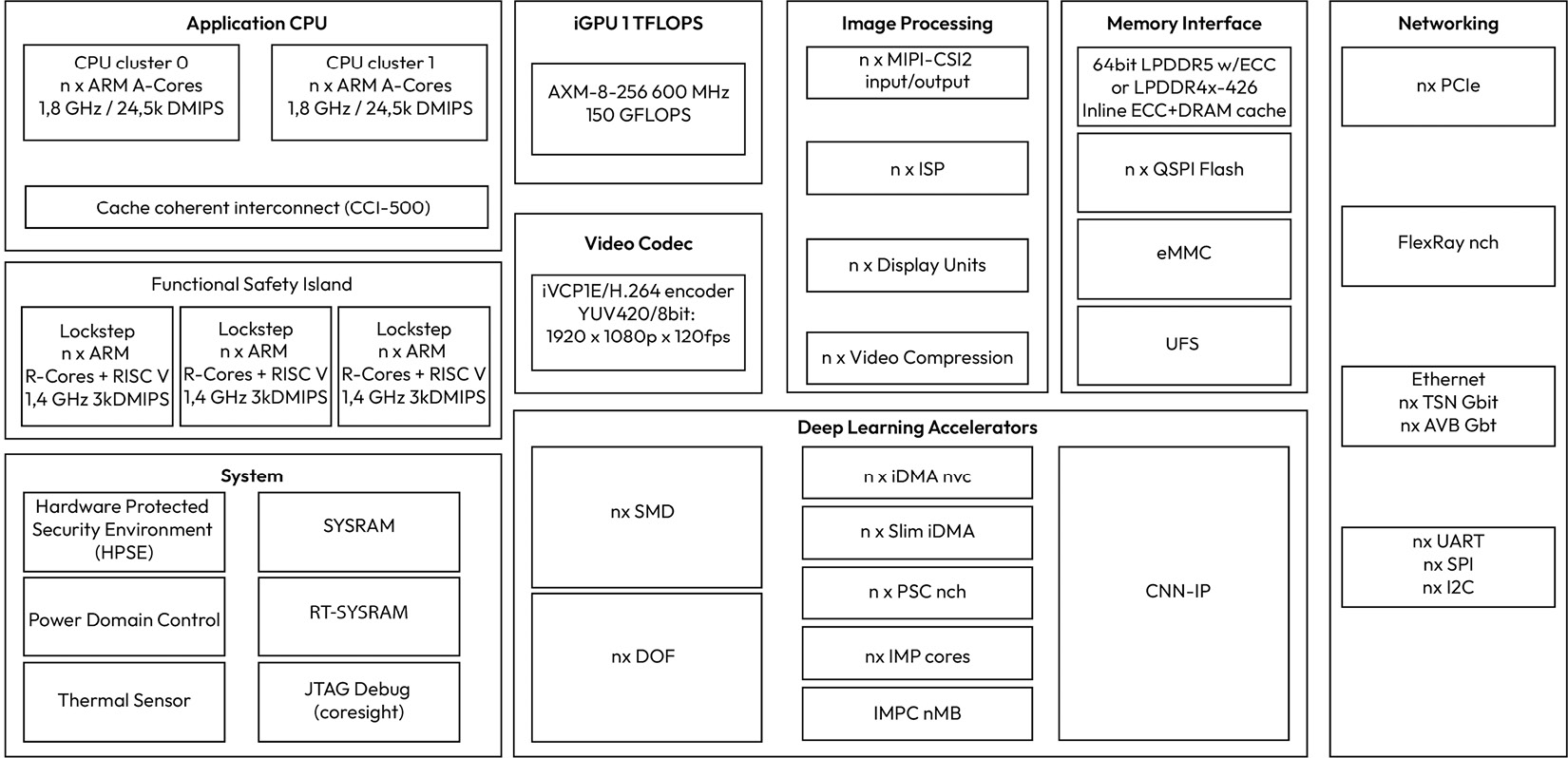
Figure 1.5 – Typical block diagram of an automotive SoC
In addition to storing typical software and calibration data, an SoC has additional unique objects of value, such as machine learning models that are programmed in storage, as well as stored camera images, videos, and vehicle logs that may contain users’ private data. Machine learning models are valuable intellectual property to the ECU supplier and the OEM that helped create them. On the other hand, camera images and video data are important to vehicle owners who care about protecting their privacy. Vehicle logs serve many purposes and can be especially useful in accident investigations. Furthermore, since memory is exposed on the PCB, an attacker can attempt to directly dump the contents of the eMMC or probe the QSPI lines to extract memory contents.
Discussion point 3
Looking at the block diagram in Figure 1.5, can you spot other assets that are interesting to an attacker who has possession of an SoC-based ECU?
Continuing with our “peeling the onion” exercise, let’s look at the MCU and SoC software layers.
Looking inside the MCU and SoC software layers
The most differentiating feature of MCU-based automotive ECUs is their hard real-time performance requirements and their high degree of determinism, both of which are critical to controlling time-sensitive operations such as braking, deploying airbags, steering, and engine combustion. As a result, an MCU periodic software task may only deviate within milliseconds, and sometimes even microseconds, from its nominal execution rate before the application starts violating its safety and reliability objectives.
Before AUTomotive Open System ARchitecture (AUTOSAR) was founded, if you wished to examine the software architecture of an ECU, you would have to work in a software team at the OEM or for an automotive supplier. But thanks to the AUTOSAR consortium’s efforts of creating a standardized basic software architecture and standard application interface layer, security professionals can gain insights into a typical ECU software architecture simply by learning the basics of the AUTOSAR software architecture.
Note
AUTOSAR is a worldwide development partnership of vehicle manufacturers, suppliers, service providers, and companies from the automotive electronics, semiconductor, and software industries.
Let’s start by looking at the MCU-based software architecture based on the AUTOSAR classic variant:
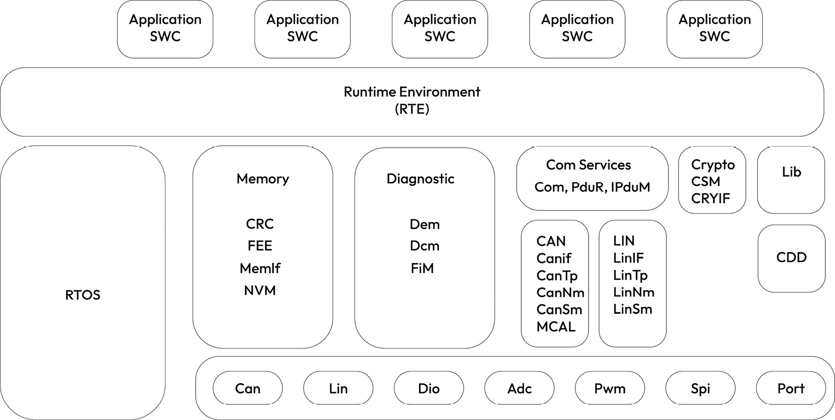
Figure 1.6 – Simplified AUTOSAR classic software block diagram
At the heart of the AUTOSAR classic software architecture is the AUTOSAR real-time operating system. The AUTOSAR operating system offers several memory, timing, and hardware resource isolation and protection guarantees to support safety-critical applications. As we will see in the following chapters, some of these safety features are also useful for hardening AUTOSAR-based applications against cyber threats.
Another signature feature of AUTOSAR classic is the hardware abstraction layer, which exposes the MCU features through well-defined interfaces to ensure software portability across different hardware platforms. Configuring the microcontroller abstraction layer (MCAL) correctly and with security in mind is a critical part of reducing the attack surface against the rest of the AUTOSAR layers.
Besides the MCAL, several AUTOSAR software layers are critical for security. For example, if the Com services layer is improperly configured, it can be abused by a software application to send spoofed messages to other ECUs on the shared CAN network. Similarly, the memory stack can be exploited to tamper with the non-volatile memory contents. The diagnostic layer can cause fake diagnostic data to be erased or inserted, or even worse, critical diagnostic services to be unlocked under unsafe conditions. Even without a deep knowledge of the AUTOSAR Crypto services layer, we can guess that cryptographic keys and critical security parameters could be exposed or at least be used illegally if this layer is not properly configured or implemented.
Discussion point 4
Can you spot additional AUTOSAR layers that may be critical for security? Hint: Think about the ECU mode management.
Before moving on, let’s look briefly at the AUTOSAR runtime environment (RTE), which separates the base software modules from the application software components. This standardized application interface layer makes it possible to interchange application software components between automotive suppliers if they abide by the RTE interface definitions. The RTE configuration dictates how application software components interact with each other, as well as with the basic software modules. Therefore, tampering with the RTE configuration has significant impacts on the ECU software security.
Note that an AUTOSAR classic-based ECU software is built as a single software executable image, along with one or more calibration images.
An important software subsystem for MCU-based ECUs that is not covered by AUTOSAR is the flash bootloader, which manages how the ECU software is started and updated, two areas that are critical for security:
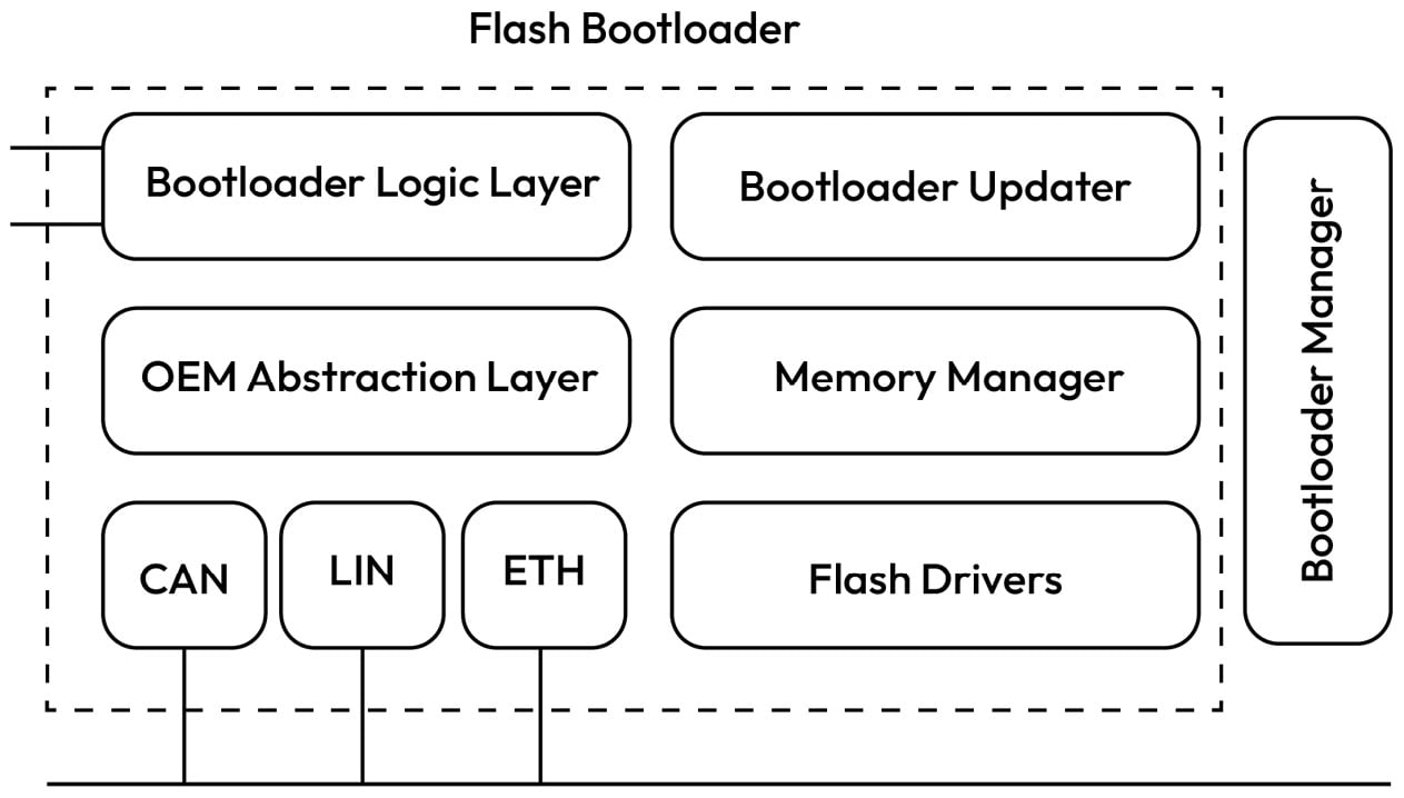
Figure 1.7 – Block diagram of a typical bootloader architecture
At startup, the flash bootloader performs basic hardware initialization and may control which software partition is executed based on the partition validation check results. Manipulating this stage can result in the startup of a tampered application or the improper safety and security initialization of the system. During runtime, the bootloader provides the functionality to reprogram the software and calibration images either through a diagnostic client or through an over-the-air (OTA) application. Illegal access to the flash bootloader update mechanisms can result in the ECU being programmed with unsafe or maliciously crafted software. Let’s assume the bootloader manages two partitions – one that contains a backup image and one that contains a recently updated image that must be booted. The bootloader memory flags that determine which software partition to boot after reset are critical for security because if they’re tampered with, this can result in the execution of an invalid or corrupt software image. Additionally, flash drivers containing the routines to erase and reprogram flash contents are important for security as they can be misused to reprogram or erase the ECU software or calibration data.
Discussion point 5
Investigate the software layers of the bootloader to see whether you can spot any services that can be abused by an attacker so that they can reprogram or erase the software.
Once again, let’s turn our attention to our SoC-based ECUs and look inward at the software architecture. Luckily, AUTOSAR has also standardized a software architecture that targets such systems through the AUTOSAR adaptive variant. While AUTOSAR adaptive has not reached the level of market adoption as AUTOSAR classic, it still serves as a useful reference. A key feature of this software architecture is the transition from signal-based software design to a service-oriented architecture (SOA). Rather than a monolithic software image built for a specific ECU with a pre-generated RTE, AUTOSAR adaptive offers a flexible architecture that allows for dynamically updated and deployed applications. Another key feature is its reliance on high-bandwidth networking technologies such as Ethernet:
Figure 1.8 – AUTOSAR adaptive block diagram (credit: AUTOSAR)
The adaptive architecture offers the main set of basic services needed to enable computationally intensive user applications. Rather than defining its own operating system, AUTOSAR adaptive defines an operating system interface layer that is compatible with any POSIX PSE51-compliant operating system. This ensures the portability of the AUTOSAR adaptive implementation across various operating systems and hardware platforms. The POSIX PSE51 profile represents the core set of POSIX APIs, which include support for features such as thread priority scheduling, thread-safe functions, synchronized I/O, real-time signals, semaphores, shared memory, inter-process communication (IPC) message passing, as well as a few utilities. Moreover, AUTOSAR adaptive can be hosted directly on a single hardware platform or as a virtual machine, sharing the platform with other operating system instances. A brief look at the AUTOSAR adaptive software architecture shows several security-related concepts. For one, data read or written to the non-volatile storage through the persistency cluster can be considered security-relevant. Error information reported through the platform health management cluster to enable the user application to take safe action is also worthy of protection. Communication data handled through the communication management cluster is another interesting area to consider when you’re analyzing the security of an adaptive-based system.
Discussion point 6
How about the logs captured by the Log and Trace cluster? What does the cryptography cluster manage, and could these assets be vulnerable? How about the Update and Configuration Management cluster?
Before we finish this section, we must look at how SoC-based ECUs are booted and updated:
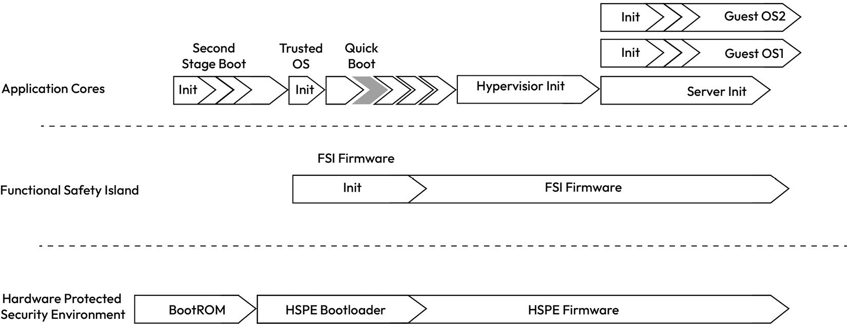
Figure 1.9 – Example boot flow from a typical SoC
Unlike the flash bootloader of the MCU-based ECU, SoC-based ECUs rely on a series of bootloaders that load software and calibration data from the external non-volatile memory into DRAM and other internal volatile memory types before handing control over to the respective cores that run the loaded firmware and software. The boot process typically starts with a MaskROM boot partition, which performs the initial hardware configuration, loads the next boot stage, and then jumps to the next boot partition after verifying its integrity and authenticity (assuming secure boot is enabled). This process continues until all firmware is booted in a staged fashion up to the point where the hypervisor kernel is started (if multiple virtual machines are supported). The hypervisor, using a loader utility, then loads one or more guest operating systems in memory and allocates the necessary CPU, memory, and hardware resources to allow the guest operating system to function as an isolated virtual machine. The latter is then responsible for launching its applications and managing its resources. Alternatively, if the operating system is running directly on the hardware (also known as a host OS), then a hypervisor is not needed. The boot sequence is one of the most security-critical execution paths of the ECU because any exploitable weakness in the boot chain can result in the execution of malicious software, which can spell disaster for a safety-critical ECU.
When it comes to reprogramming the firmware and software binaries, different types of update solutions exist, including OTA. AUTOSAR adaptive provides one reference architecture through its update and configuration management cluster. This enables updates through a diagnostic client in addition to an OTA application. As you might have guessed, this functionality is also security-critical as it exposes the software platform to the possibility of malicious software updates and the execution of potentially dangerous code.
Now that we have been introduced to the general hardware and software architecture of ECUs, let’s explore the various ECUs and the domains in which they are grouped based on their related functionality. This will prove useful in later chapters as we analyze the threats that impact such ECUs.
ECU domains
An ECU domain is a grouping of ECUs that collaborate to achieve a common vehicle-level function, such as propulsion control or active braking. Such a grouping improves the efficiency of communication by limiting communication messages to the ECUs that are most co-dependent, thus reducing network congestion caused by non-domain-related messages. As the vehicle architecture evolves, ECU domains may be arranged in different configurations (as we will see in the last section of this chapter). For now, our focus is on understanding the various ECUs that are typically found in a standard vehicle architecture.
Note
The following list of ECUs is meant to be representative of ECUs found in vehicles rather than a comprehensive one with the aim of highlighting the security relevance of each.. Some ECU names can change as OEMs differ in the way they partition vehicle functions across different control units.
Fuel-based powertrain domain
The fuel-based powertrain domain is responsible for producing power in an internal combustion engine (ICE) and transmitting it to the wheels. An attacker who can gain access to any ECU in the powertrain domain may be able to affect the vehicle’s longitudinal motion, which has an obvious safety impact. However, the more common attack target of this domain is engine tuning to illegally increase performance, which has the side effect of increasing vehicle emissions.
Engine control module (ECM)
A vehicle engine’s performance is precisely regulated by the ECM, which pulls data from sensors layered throughout the engine. Among the control functions of the ECM are the engine starting procedure, spark plug ignition, fuel injection, and the cooling process.
Transmission control module (TCM)
The TCM uses different gear ratios to convert a fixed engine speed and torque into a variable driving speed and torque in automatic transmission vehicles. The TCM determines when to shift gears to optimize the vehicle’s performance, balancing factors such as fuel efficiency, power, and engine protection. This is based on a variety of input data, such as engine speed (RPM), vehicle speed, throttle position, and load on the vehicle.
Electric drive powertrain domain
This domain is responsible for battery charging and managing and distributing electric power to the motors, as well as the other electronics that require varying power levels. Like the fuel-based powertrain domain, protecting this domain against security breaches is essential to prevent several hazards, such as erratic vehicle motion control and unsafe battery management. The latter is a unique problem for electric vehicles with the potential to cause catastrophic thermal events if the batteries are not operated safely.
Battery management system (BMS)
The BMS’s primary function is to manage the state of charge (SoC) and state of health (SoH) of the battery pack by controlling the charging and discharging of the battery cells. It also monitors the battery pack’s status for hazardous conditions such as overheating or high current events to ensure fail-safe action is taken before it leads to a catastrophic failure.
Onboard charger
The onboard charger’s primary role is to convert the AC power provided by the electric vehicle supply equipment (EVSE) into DC power, which can then be used to charge the vehicle’s battery pack. This involves controlling the rate of charging to ensure the battery is charged safely and efficiently.
Additionally, it provides communication between the EVSE and the vehicle’s charging system. This is done using a power-line communication protocol, which allows data to be sent over the electrical power lines. This can be used to negotiate the charging rate based on factors such as the vehicle’s current state of charge, the capacity of the EVSE, and the temperature of the battery [8].
DC-AC converter
In electric vehicles, the high-voltage DC-AC converter, also known as the inverter, converts DC output from the battery pack to AC power for the electric motor(s).
Powertrain electronic control unit (PECU)
This ECU manages the speed and acceleration of the electric motors by controlling the supplied voltage frequency and magnitude.
Chassis safety control domain
The chassis safety control domain encompasses a variety of ECUs and in-vehicle sensors with a clear focus on active and passive safety management. Since the ECUs in this domain are responsible for vehicle safety, it can be argued that this domain is at the top of the list for security professionals regarding what needs to be protected against cyberattacks.
Electronic braking control module (EBCM)
The EBCM is a specialized module that supplies brake pressure to the wheels to achieve several active safety functions, such as ABS, ESC, and automatic emergency braking.
Airbag control module
As a passive safety system, airbags protect occupants from bodily harm in the case of a collision by inflating the airbags through controlled explosions of the squibs embedded in the airbag.
Electronic power steering (EPS)
The EPS is responsible for providing electronic steering assistance to the driver through the actuation of steering motors. The EPS can provide several enhanced driver assistance features, such as lane departure warnings and lane correction.
Advanced driver assistance (ADAS) control module
While several ADAS functions can be integrated within the EBCM and EPS, a dedicated ECU is common in more modern vehicles to achieve higher levels of autonomy.
This module can command the ECM, EBCM, and EPS to control engine torque and apply braking and steering based on the situation at hand. It integrates inputs from multiple sensors, which makes it possible for the ADAS ECU to perform autonomy functions such as automated parking and autonomous highway driving, to name a few.
Interior cabin domain
The interior cabin domain encompasses the comfort features expected from a modern vehicle. At first glance, this domain may seem less critical for security. On the contrary, due to its ability to control physical security, this domain is among the most targeted by attackers today as a breach of this domain translates to vehicle break-in and theft.
Body control module (BCM)
The BCM manages the remote keyless entry and access to the vehicle’s interior. Additionally, it can control seat positions and power windows, light controls, and windshield wipers.
Climate control module (CCM)
The primary function of the CCM is to provide heating and cooling of the cabin. It typically heats the air with a heater core and cools the air with an evaporator and a refrigerant that absorbs heat from the cabin’s air.
Infotainment and connectivity domain
The vehicle functions that engage the driver through the human-machine interface (HMI) are usually grouped in the infotainment domain. ECUs in this domain include the vehicle’s head unit, the central console, as well as the driver-facing instrument cluster. You have probably guessed by now that this domain is also security-critical due to the rich user interfaces it offers.
In-vehicle infotainment (IVI)
The IVI offers entertainment and information delivery to drivers and passengers. The IVI system accepts user input through touchscreens and physical controls and serves the occupants with audio, video, and navigation data. In some cases, the instrument cluster can be integrated with the IVI to provide the driver with a digital display of vehicle information such as speed, fuel level, and more. IVI systems enable vehicle occupants to connect their phones through Bluetooth and USB, making them an attractive target for attackers.
Telematics control unit (TCU)
The TCU is the primary remote access point to the vehicle and therefore is considered high on the list of security-critical ECUs. Among its features are the reception of GPS signals and providing connectivity through cellular and Wi-Fi communication to facilitate OTA updates, as well as the transmission of remote messages such as telemetry data and emergency assistance requests.
Cross-domain
The interconnection of all domains can be viewed as its own domain whose primary objective is providing reliable communication across the previously mentioned domains when message exchange is needed.
Central gateway (CGW)
While some vehicles may rely on individual ECUs to act as gateways between two or more vehicle subsystems, a more common trend is to dedicate a single gateway ECU to perform this function. When a CGW is used, it behaves as an in-vehicle router by allowing ECUs from different network segments to communicate with one another. The CGW translates data across different network systems, such as CAN to CAN, CAN to Ethernet, and CAN to LIN. Due to its access to all vehicle domains, the CGW can play an important role in security by segmenting the network architecture and dropping unwanted traffic.
Discussion point 7
Can you think of some unique assets of the CGW? Hint: Network filter rules are one such asset.
Now that we have explored the different ECUs and ECU domains, it’s time to dive into the networking technologies that enable them to exchange information.
Exploring the in-vehicle network
The plethora of ECUs, sensors, and actuators gave rise to a diverse set of in-vehicle networking technologies. A common goal of these technologies is the need for reliable communication with deterministic behavior under harsh environmental conditions within low-cost constraints. The bulk of the ECUs rely on signal-based communication through automotive bus systems such as Controller Area Network (CAN/CAN-FD), FlexRay, Ethernet, and Local Interconnect Network (LIN). The increased demand for network bandwidth is constantly driving the in-vehicle networks to transition to higher bandwidth solutions such as Ethernet and GMSL.
While securing in-vehicle networks shares common challenges with general network security, the real-time performance constraints and limited payload sizes present unique challenges for many of the automotive networking protocols. In the following section, we will survey the most common automotive networking technologies and touch upon their unique security challenges. Understanding the primary features and common use cases of these protocols will serve as a basis for analyzing the security of the in-vehicle networking protocols in the following chapters.
CAN
It is hard to work on vehicle security without learning about how CAN works and the various security problems it suffers from. CAN is a serial communications protocol that is perfect for real-time applications that require dependable communication under harsh environmental conditions. It has been and remains a popular communication protocol due to its low cost and excellent reliability. CAN is used in a variety of vehicles, including commercial trucks, cars, agricultural vehicles, boats, and even aircraft:
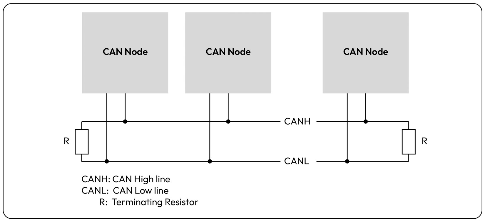
Figure 1.10 – Typical bus layout with multiple CAN nodes sharing a single CAN channel
The CAN physical layer supports bitwise bus arbitration, which ensures that the CAN node transmitting with the lowest CAN ID wins the arbitration, causing the other nodes to wait until the bus is idle before re-attempting transmission. This arbitration scheme can be potentially harmful if CAN nodes misbehave by attempting to acquire bus access greedily.
Another important feature of CAN is its built-in error handling strategy, which ensures that nodes experiencing transmit errors enter a bus-off state to stop disturbing other nodes. This minimizes bus disturbance and allows for application layer strategies to retry transmission after a back-off period. These rules are upheld if the CAN controller is conforming, as is the case with standard CAN-based devices. Note that in later chapters, we will examine the threat of non-conforming CAN controllers, which are intentionally designed to violate the physical and data link layer protocols. In those cases, the malicious CAN node can inject bit flips, creating continuous availability issues with the physical CAN channel.
When it comes to the flavors of CAN, there are three versions: CAN 2.0, CAN-FD, and the latest, CAN XL. CAN 2.0 is the most used since it’s the legacy protocol but its maximum payload size of eight bytes and a typical baud rate of 500 kbps makes it unsuitable for more bandwidth-hungry applications. As a result, CAN-FD was added, offering a larger payload of up to 64 bytes and a faster payload data rate, which is typically 2 Mbps. The final variant of CAN is CAN XL, which offers a maximum payload size of 2,048 bytes and up to 20 Mbps. Note that while each CAN protocol advertises a higher theoretical baud rate limit, factors such as bus length, bus load, signal quality, and EM interference force a lower typical baud rate to ensure the reliability of communication.
The CAN FD message’s frame format is shown in the following figure to help you visualize what a CAN frame looks like:
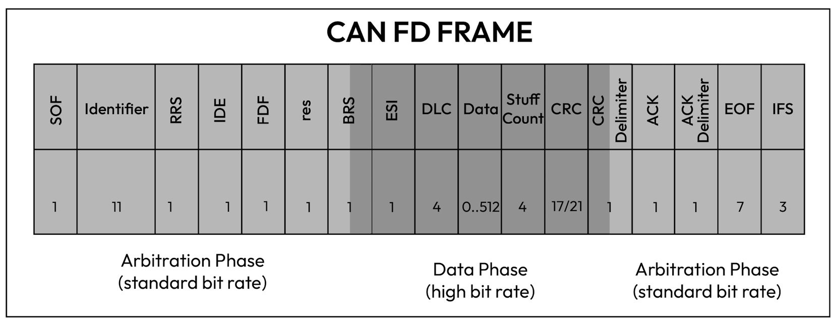
Figure 1.11 – CAN FD bit frame layout
CAN node receivers use the CAN identifier to determine how to interpret the payload content, also known as the PDU. The CAN ID is important for setting up acceptance filters so that a receiver can determine which messages it wants to receive or ignore. In addition to the CAN ID, the transmitter specifies the DLC field, which indicates the payload size, and the data field, which contains the actual payload. Note that the CRC field is automatically calculated by the CAN controller to ensure the receiver detects flips in the CAN frame occurring at the physical layer. Above the CAN data link layer, several CAN-based protocols exist, such as the transport protocol, diagnostic protocol, network management, and OEM-defined PDU Com layers. Diagnostics are particularly interesting for security as they allow an external entity with access to the onboard diagnostics (OBD) interface to send potentially harmful diagnostic commands. In later chapters, we will take an in-depth look at how the OBD protocol can be abused to tamper with emissions-related diagnostic tests, as well as OEM-specific diagnostic services. Another important use case of CAN is the transmission and reception of safety-critical PDUs that include sensor data, vehicle status messages, and actuation commands.
Discussion point 8
Given the small payload size of CAN 2.0 messages, and the low tolerance for message latency, can you think of a suitable way to protect the message integrity from malicious tampering?
FlexRay
A big driver for the automotive industry to transition to FlexRay was the desire for a more deterministic communication protocol that could offer guaranteed bandwidth to safety-critical messages. Unlike CAN, which allows the transmitter with the lowest CAN ID to always win the arbitration, FlexRay allocates time slots based on a Time Division Multiple Access (TDMA) structure:
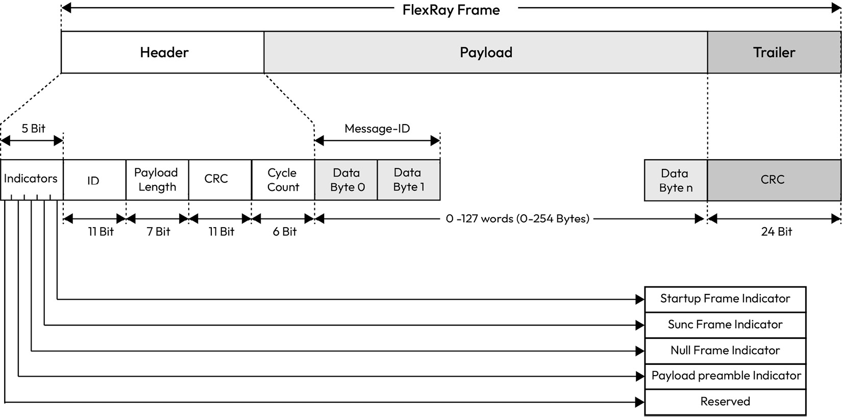
Figure 1.12 – FlexRay frame layout
Another benefit of FlexRay over CAN and CAN FD is the maximum payload of 254 bytes. Moreover, FlexRay offers a redundant configuration for the communication channel to reduce the possibility of failure with a data rate of up to 10 Mbps per communication channel. Where redundant communication is not critical, the redundant channel can be leveraged to boost the data rate to 20 Mbps. FlexRay features a static slot and a dynamic slot to allow fixed messages in reserved time slots to be transmitted, as well as dynamic messages that can be transmitted non-cyclically. The payload length has the same value for all messages transmitted in the static slot. On the other hand, the dynamic slot can have payload lengths of varying sizes.
Discussion point 9
Could the dynamic slot be abused by a malicious FlexRay node?
The payload preamble indicator field indicates whether a frame is a dynamic or static FlexRay message. In a dynamic message, the first two bytes of the payload are the message identifier, which allows for precise identification of the payload and finer control of acceptance filtering. The NULL frame indicator is used to send a message with a payload of zeroes to indicate that the transmitter was not ready to provide data within its allocated time slot. The CRC field is automatically calculated by the FlexRay controller to ensure channel errors are detected by the receiver. Critical to the correct operation of the FlexRay protocol is the use of time synchronization. Without this, senders will start transmission in the wrong time slots and the protocol will lose its reliability. In a FlexRay cluster, at least two FlexRay nodes must act as the synchronization nodes by transmitting a synchronization message in a defined static slot of each cycle. All FlexRay nodes can then compute their offset correction values using the fault-tolerant midpoint (FTM) algorithm. The FTM algorithm is used to ensure that the nodes in the FlexRay network are synchronized to exchange data in a coordinated and reliable manner. The FTM algorithm works by using a central node, known as the FTM, which acts as a reference point for the other nodes in the FlexRay network. The FTM node sends periodic synchronization messages to the other nodes in the network, which, in turn, use these messages to adjust their internal clocks to match the clock of the FTM node.
Discuss point 10
Can you think of a unique attack method that the FlexRay cluster is exposed to? Could the FTM algorithm be abused by a malicious node to cause a loss of network synchronization?
LIN
A LIN bus is a single-master, multiple-satellite networking architecture based on the universal asynchronous receiver-transmitter (UART) protocol and is typically used for applications where low cost is more critical than data transmission rates. In a LIN network, the master sends a command containing a synchronization field and an ID, while the satellite responds with a message payload and checksum. Like CAN 2.0, the payload size is up to 8 bytes but at a much lower bit rate, typically 19.2 kbps:
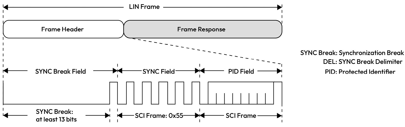
Figure 1.13 – LIN frame structure
LIN communication is based on a schedule table maintained by the LIN master, who uses it to issue LIN header commands directed at specific LIN satellites. LIN is perfect for sensor and actuator networking applications such as seat control, window lifters, side-view mirror heating, and more. A typical vehicle network will contain a CAN node that is also a LIN master acting as a gateway between the CAN network and the LIN sub-network. This enables such a master to control the LIN satellites by sending them actuation commands and diagnostic requests. Therefore, the LIN master node is a critical link in exposing deeply embedded sensors and actuators in the rest of the vehicle through a CAN-LIN gateway node.
Discussion point 11
Can you think of a way the LIN bus can become exposed to security threats?
UART
The UART communication protocol supports the asynchronous transmission of bits and relies on the receiver to perform bit sampling without the use of a synchronized clock signal. The transmitting UART node augments the data packet being sent with a start and stop bit in place of a clock signal. The standard baud rate, which can go up to 115,200 bps, is 9,600 bps, which is adequate for low-speed communication tasks:
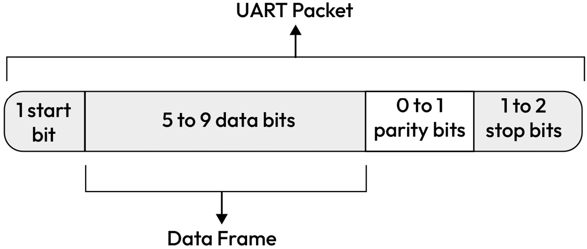
Figure 1.14 – A UART packet showing start, stop, data, and parity bits
UART is typically used in automotive applications to open debug shells with an MCU or SoC, which naturally makes it an interesting protocol for attackers to abuse.
SENT
The Single Edge Nibble Transmission (SENT) bus, known as SAE J2716, provides an accurate and economical means of transmitting data from sensors that measure temperature, flow, pressure, and position to ECUs. The SENT bus is unique in that it can simultaneously transfer data at two different data rates of up to 30 kbps, outperforming the LIN bus. The primary data is normally transmitted in the fast channel, with the option to simultaneously send secondary data in the slow channel.
A typical SENT frame consists of 32 bits, as shown in Figure 1.15, and breaks up the data into 4-bit nibbles that are terminated by a CRC to ensure frame integrity against corruption errors:
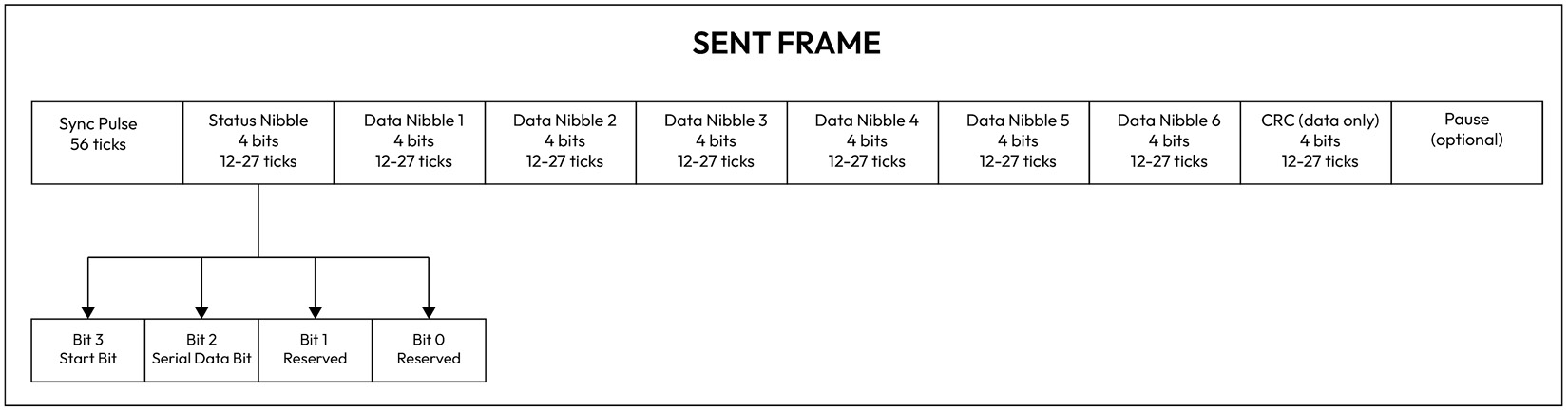
Figure 1.15 – SENT frame format
Although SENT is robust, easy to integrate, and has high accuracy, the SENT messages can still be affected by noise, timing problems, and subtle differences in implementations, which limits its use to specific sensor types.
GMSL
Gigabit Multimedia Serial Link (GMSL) is a high-speed multigigabit serial interface used originally in automotive video applications such as infotainment and advanced driver assistance systems (ADASs). It allows for the transmission of high-definition video and audio signals between components within the vehicle, such as cameras, displays, and audio processors. It uses a serializer on the transmitter side to convert data into a serial stream, and a deserializer on the receiving side to convert the serial data back into parallel words for processing. GMSL can transfer video at a speed of up to 6 Gbps:
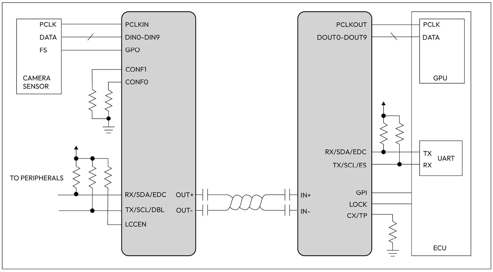
Figure 1.16 – GMSL use case diagram based on analog devices (ADI) GMSL deserializer
Figure 1.16 shows a typical configuration of a camera application where a serializer chip (shown on the left) is connected to a camera sensor, while a deserializer chip (shown on the right) is connected to the ECU. In addition to its use in audio and video transmission, GMSL technology is used in automotive applications to transmit other types of data, such as high speed sensor data and control signals.
I2C
Inter-Integrated Circuit (I2C) is a two-wire serial communication protocol mainly used for communication between an MCU or SoC and a peripheral such as a camera sensor or a memory chip (EEPROM) that is positioned near the controlling unit. I2C supports data rates of up to 5 Mbps in ultra-fast mode and as low as 100 kbps in standard mode. I2C comes with an address frame that contains the binary address of the satellite device, one or more data frames of 1 byte in size that contain the data being transmitted, start and stop conditions, read/write bits, and ACK/NACK bits between each data frame:
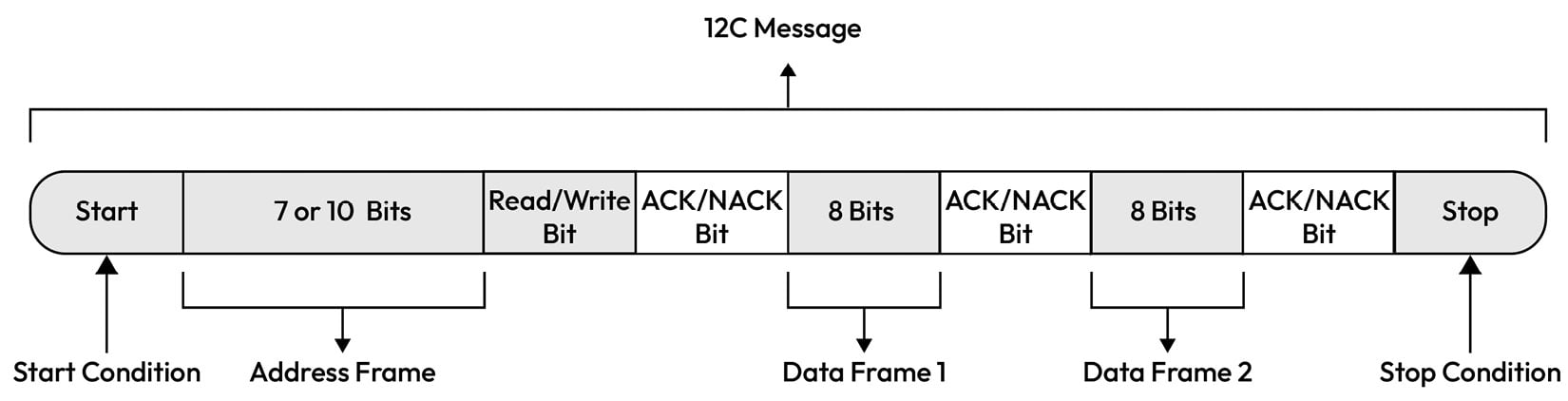
Figure 1.17 – I2C message layout
Ethernet
The constant growth of bandwidth demands due to content-rich use cases has led the automotive industry to gradually adopt Ethernet through a set of IEEE standards known as Automotive Ethernet [9]:
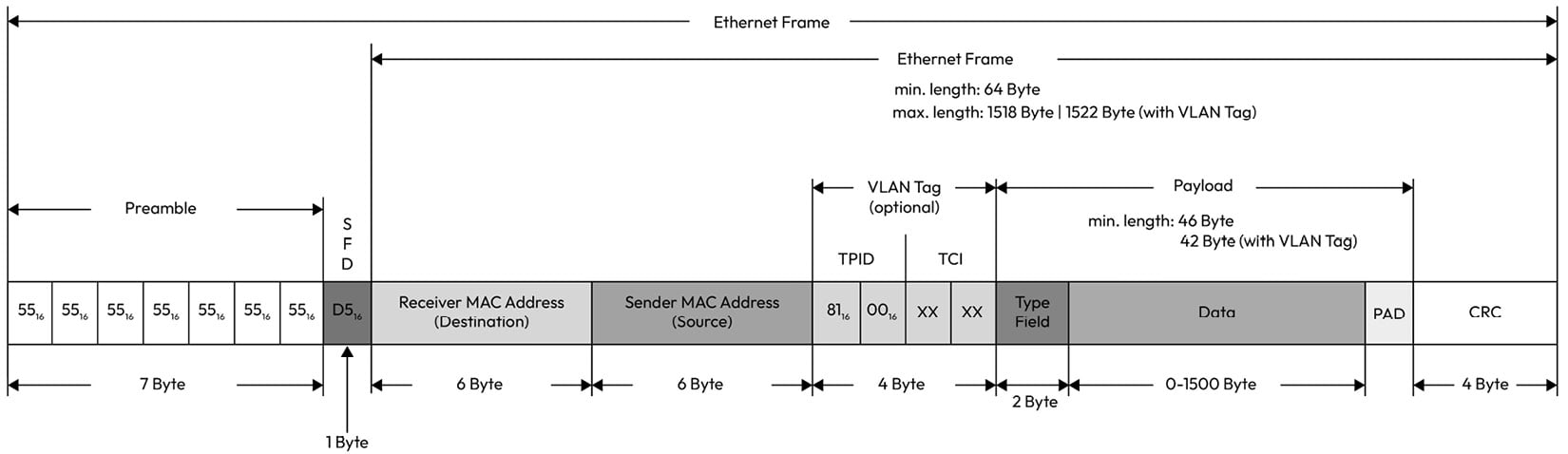
Figure 1.18 – Ethernet frame layout
Ethernet-based communication offers high bandwidth with great flexibility for integration with standard products outside the automotive domain. Automotive Ethernet covers a data rate range starting from 10 Mbit/sec standardized through 10Base-T1S up to 10 Gb/sec standardized through 10Gbase-T1. This makes it suitable for a range of automotive use cases, from time-sensitive communication to high-throughput video applications.
One of the primary differences between Ethernet and automotive Ethernet is the physical layer, which is designed to handle stringent automotive EMC requirements. Another difference is the introduction of the IEEE time-sensitive networking (TSN) standard, which offers preemption to allow critical data to preempt non-critical data, time-aware shaping to ensure a deterministic latency in receiving critical data, precise timing (PTP) to synchronize clocks within the network, per-stream filtering to eliminate unexpected frames, frame replication, and elimination, as well as an audio-video transport protocol for infotainment-related use cases.
J1939
SAE J1939, defined by the Society of Automotive Engineers (SAE), is a set of standards that defines how ECUs communicate via the CAN bus in heavy-duty vehicles:
|
Layer |
Name |
Standard |
|
7 |
Application |
SAE J1939-71 (applications) SAE J1939-73 (diagnostics) |
|
6-4 |
Presentation, Session, and Transport |
Not used but included in the Data Link layer |
|
3 |
Network |
J1939-31 |
|
2 |
Data Link |
J1939-21 |
|
1 |
Physical |
J1939-11 |
For communication among ECUs within the truck network, the standard ISO 11898 CAN physical layer is used. However, for communication between the truck and the trailer, a different physical and data link layer based on ISO11992-1 is used.
At the data link layer, J1939 supports peer-to-peer messages in which the source and the destination address are provided in the 29-bit CAN ID. It also supports broadcast messages, which contain only the source address. This allows multiple nodes to receive the message. A unique feature of J1939 over traditional CAN is the Parameter Group Number (PGN) and Suspect Parameter Number (SPN). Unlike passenger vehicles that rely heavily on OEM-defined PDUs, J1939 comes with a set of standard PGNs and SPNs, which makes it easier for people observing the J1939 CAN bus to decode the meaning of the messages.
Let’s look at an example PGN and its corresponding SPNs, as defined in the SAE J1939 standard.
The PGN 65262 is reserved for engine temperature and given a fixed transmission rate of 1s, a PDU length of 8 bytes, and a default priority of 6. The 8 bytes are distributed as follows:
|
Start Position |
Length |
Parameter Name |
SPN |
|
1 |
1 byte |
Engine Coolant Temperature |
110 |
|
2 |
1 byte |
Engine Fuel Temperature 1 |
174 |
|
3-4 |
2 bytes |
Engine Oil Temperature 1 |
175 |
|
5-6 |
2 bytes |
Engine Turbocharger Oil Temperature |
176 |
|
7 |
1 byte |
Engine Intercooler Temperature |
52 |
|
8 |
1 byte |
Engine Intercooler Thermostat Opening |
1134 |
The SPN is the equivalent of a signal ID that’s commonly used in signal-based communication for passenger vehicles. J1939 standardizes the SPN name, description, data length, and even the resolution to ensure the raw-to-physical interpretation is performed correctly.
When transferring data that is larger than 8 bytes, you will need to use the transport protocol, which in J1939 supports message transfers of up to 1,785 data bytes. This is done through two modes: connection mode data transfer, in which ready-to-send (RTS) and clear-to-send (CTS) frames are used to allow the receiver to control the data flow, and a broadcast announce message (BAM), which allows the sender to transmit messages without the data flow control handshake.
Discussion point 12
Can you think of ways the handshake messages can be abused by a malicious network participant?
The transport protocol supports diagnostic applications, which rely on a set of parameter groups (PGs) reserved for handling different diagnostic services. PGs designated as diagnostic message (DM) types fulfill the UDS protocol, which is commonly used for passenger vehicle diagnostics. When observing a diagnostic frame over J1939, you can easily look up the diagnostic trouble code by observing the SPN field (which contains the unique identifier of a fault parameter) and the FMI field (which contains the type of failure detected).
Finally, source address management and mapping to an actual function are handled by the network management layer. Unlike passenger vehicle network management protocols, which are designed to support ECU sleep and wakeup, J1939 uses network management to define how ECUs get admitted to the network and how device addresses are administered in dynamic networks. A simple form of J1939 network management is the transmission of the Address Claimed parameter group (PGN 0x00EE00) of every ECU after booting and before the start of communication. With Address Claim, the device name and a predefined device address are exchanged to describe the network topology. For a detailed understanding of the address claiming protocol, we encourage you to read J1939-31 (see [ 1] in the Further reading section). For now, let’s be aware that this ability to claim certain addresses can present security challenges if a network participant is not behaving honestly.
So far in this chapter, we’ve surveyed the most common in-vehicle networks. We intentionally left out external network types such as Wi-Fi, Bluetooth, 5G cellular, GNSS, and RF communication. We will explore threats that emanate from these communication domains in the following chapters. Now that we have learned how to interconnect components through the vehicle network, let’s explore some special vehicle components that allow an ECU to sense and react to changes in the vehicle’s environment.
Sensors and actuators
The MCU and SoC-based ECUs discussed in the previous sections would be of very little use if it were not for the sensors that feed into their control algorithms and the actuators that are driven by the output of those algorithms. Sensors and actuators enable numerous vehicle functions that enhance both the driver experience and safety aspects, such as adaptive cruise control, automatic emergency braking, and more. When it comes to sensing, modern vehicles may contain upward of 100 sensors both embedded within the ECUs as well as within the vehicle’s body. Sensors transform a variety of physical conditions, including temperature, pressure, speed, and location, into analog or digital data output.
Understanding the physical properties of the sensor and its vehicle interfaces allows us to determine how it can be affected by a cyberattack. In the following subsection, we will sample a variety of sensors to gain a perspective on how they sense inputs and the interfaces by which they transmit and receive data:
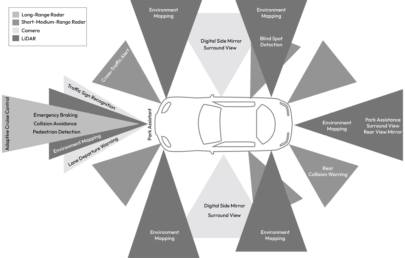
Figure 1.19 – Sensors mapped to ADAS functions providing 360-degree sensing capability
Sensor types
The sensors shown in Figure 1.19, in addition to a sample of internal sensors, are described here:
- Cameras: These enable a range of vehicle functions, such as digital rear-view mirrors, traffic sign recognition, and a surrounding view on the center display. A camera sensor produces raw image data of the surroundings by detecting light on a photosensitive surface (image plane) using a lens placed in front of the sensor. Camera data is then processed by the receiving ECU to produce the image data formatted for the camera applications. Typically, an image resolution of 8 megapixels is supported with a frame rate of up to 60 FPS. In most cases, the raw image data is serialized from the sensor over the GMSL link and deserialized by the host ECU with data transfers of up to 6 GB per second. A separate control channel is typically supported to configure and manage the sensor using a low-speed communication link such as I2C. Certain specialized cameras produce classified object information such as lane, car, and pedestrian. In all cases, attacks against cameras can impact the vehicle’s ability to correctly identify objects, which can have a serious safety impact. Additionally, user privacy can be violated if the camera data is illegally accessed.
- Light Detection and Ranging (LiDAR): This is a remote sensing technology based on the principle of emitting pulses of laser light and measuring the reflection of target objects. The interval taken between the emission and reception of the light pulse enables the estimation of the object’s distance. As the LiDAR scans its surroundings, it generates a 3D representation of the scene, also known as a point cloud. LiDAR sensors are used in object detection algorithms and can support the transmission of either raw or pre-processed point cloud data. Such sensors typically interface to the host ECU through a 1000Base-T1 Ethernet link. Attacks against LiDAR can impact the vehicle’s ability to detect objects, which can have a safety impact.
- Ultrasonic sensors: These are electronic devices that measure the distance of a target object by emitting ultrasonic sound waves and converting the reflected sound into an electrical signal. Ultrasonic waves are sound waves transmitted at frequencies higher than those audible to humans and have two main components: the transmitter (which emits the sound using piezoelectric crystals) and the receiver (which transforms the acoustic signal into an electrical one). Ultrasonic sensors typically interface with the host ECU via CAN. Attacks against the ultrasonic sensors can impact the vehicle’s ability to detect objects during events such as parking, which can have a safety impact.
- Radio Detection and Ranging (Radar): This is based on the idea of emitting EM waves within the region of interest and receiving dispersed waves (or reflections) from targets, which are then processed to determine the object range information. This allows the sensor to determine the relative speed and position of identified obstacles using the Doppler property of EM waves. A radar sensor’s resolution is much more coarse than a camera’s and typically interfaces to the host ECU via CAN or Ethernet. Like LiDAR, Radar is used in autonomous driving applications, so attacks impacting its data have implications for vehicle safety.
- GNSS sensors: These use their antennas to receive satellite-based navigation signals from a network of satellites that orbit the Earth to provide position, velocity, and timing information. These sensors typically interface with the host ECU via CAN or UART. Attacks on GNSS sensors can impact the vehicle’s localization ability, which is critical for determining the vehicle’s location within a map to establish a sense of the road and buildings. Also, GNSS input is necessary for receiving global time, which, if compromised, can interfere with the vehicle’s ability to get a reliable time source.
- Temperature sensors: These are used for sensing temperature, typically using a thermistor, which utilizes the concept of negative temperature coefficient. A thermistor with a negative temperature coefficient experiences lower resistance as its temperature increases, which allows you to correlate a change in temperature to a change in the electric signal flowing through the thermistor. Other techniques besides a thermistor exist, such as infrared (IR) sensors, which detect the IR energy emitted by an object and transmit a signal to the MCU for processing. Temperature sensors are used in many automotive applications both inside the MCUs and SoCs as well as on the PCB board itself. They are essential for temperature monitoring to satisfy safety requirements. Temperature sensors embedded within the MCU typically provide temperature readings through a simple register read operation, while external temperature sensors can be interfaced to the MCU via general-purpose input/output (GPIO) pins, analog-to-digital converters (ADCs), or I2C. Attacks on temperature sensors can impact the ECU’s ability to monitor its temperature, potentially leading to undetected overheating situations, which can be hazardous.
- Vehicle dynamics sensors: These enable active and passive safety ECUs to determine the vehicle’s motion state, which factors into the algorithms for controlling steering, braking, and airbag deployment. Attacks on any one of these sensors will have a direct safety impact as the control algorithms consuming their data would be making erroneous calculations that would likely result in an unsafe control action. Here is a sample of the most common sensors that are used within this domain:
- Inertial measurement units (IMUs) sense the physical effects of motion along six dimensions: yaw, roll, and pitch rate as well as lateral, longitudinal, and vertical accelerations. This helps the vehicle determine when it is experiencing hazardous events, such as slipping on ice or roll-over. IMUs leverage MEMS technology to sense acceleration through the capacitive change in the micromechanical structures of the sensor. They are typically interfaced with the host ECU via CAN.
- The steering angle sensor design is typically based on Giant Magnetoresistance (GMR) technology. It is positioned onto the steering shaft to measure the steering angle value. The sensor outputs both the steering angle value and steering angle velocity over CAN. Wheel speed sensors use a Hall-sensing element in a changing magnetic field to produce an alternating digital output signal whose frequency is correlated to the wheel speed. The wheel speed sensor is typically hardwired to the host ECU, normally the EBCM.
- The brake pedal sensor, also known as the angular position sensor, is normally based on a magnetic field sensor, which enables contactless pedal angle measurement. This is typically used in the regenerative braking of hybrid and electric vehicles. This sensor is hardwired to the host ECU, normally the EBCM.
The accelerator pedal sensor, also known as the rotary position sensor, uses a magnetic rotary sensor with a Hall element to measure the angular position. The sensor is hardwired to the host ECU, normally the ECM. In addition to sensors mounted inside the vehicle, a wide range of sensors exist that are integrated directly within vehicle electromechanical components such as the engine’s mass air flow rate sensor, which is used for electronic fuel injection. Another important engine sensor is the exhaust gas oxygen sensor, which enables the exhaust emissions catalyst to operate correctly. Attacks against these types of sensors can have environmental impacts due to their role in emissions control.
Understanding the sensors that are used within your vehicle, their physical characteristics, and the method by which they are interfaced with ECUs is important for understanding the threats that may apply to those sensors. Therefore, you are encouraged to make an inventory of all the sensors related to your ECU as preparation for the next chapters when we study threats impacting sensors.
The sensor inputs to the control algorithms of an ECU would be of very little value if not for the components that convert the ECU output into physical action. In the next subsection, we will focus on these types of components and learn how they can be controlled by the ECU.
Actuators
An actuator is a component that can be electronically controlled to move a mechanism or a system. It is operated by a source of energy, such as an electric current, hydraulic fluid pressure, or pneumatic pressure, which is then converted into motion. The ECU contains the electronic components necessary to interface with the actuators and apply the software-driven control algorithms. Understanding how actuators are controlled and the effect they can have if misused is important for vehicle cybersecurity. Here’s a sample of some of the common actuators that we expect to find in a vehicle:
- AC servo motors: These are electrical devices that are driven by an ECU to accurately rotate mechanisms within the vehicle. These motors are used in many use cases within the vehicle, such as assisting steering by controlling the motion of the steering column, as demanded by the EPS.
- Brushless DC motors: In powertrain applications, brushless DC motors can be found in the shifting function of the transmission, as well as the torque distribution controller in transfer cases and differentials. Several possible interfaces exist to control these motors, such as Pulse Width Modulation (PWM) and CAN.
- Electric window lift drives: These enable the opening and safe closing of windows. They typically offer self-locking gear units to prevent windows from being forced open from the outside. These drives are normally interfaced with the BCM through LIN.
- Seat drives: These use one - or two-stage gear motors to control seat adjustment. It is normally controlled by the BCM through LIN.
- Sunroof drive: It produces high torque to control the sunroof’s position through a motor and gear system that is controlled by the BCM.
- Fuel pump: This is electrically controlled by the ECM to provide the engine with fuel at the required pressure.
- Injectors: These are solenoid-equipped injection nozzles that the ECM manages. The ECM determines the basic fuel injection time based on intake air volume and engine RMP, as well as the corrective fuel injection time based on engine coolant temperature and the feedback signal from the oxygen sensor during closed-loop control.
While actuators are normally not directly accessible by an attacker, it is important to understand the impacts of attacks targeting them and whether feasible attack paths exist to reach them.
Now that we have explored the various ECUs, sensors/actuators, and networking technologies that enable their communication, we will consider the different topologies that shape how these components are interconnected and used.
Exploring the vehicle architecture types
The different ways an E/E architecture can be built impact the vehicle attack surface, as well as the attack feasibility associated with certain attack paths. As we will see in Chapter 3, some E/E architectures are more vulnerable to cyberattacks than others.
Throughout the years, the E/E architecture has evolved from a highly distributed one with direct mapping between vehicle functions and ECUs to a more centralized architecture where vehicle functions are consolidated into a few yet computationally powerful domain controllers. Figure 1.20 shows the expected progress of E/E vehicle architectures. It starts with the highly distributed architecture, which consists of highly interconnected function-specific ECUs. The second evolution represents the domain-centralized architecture, which utilizes domain-specific ECUs that consolidate the features of multiple ECUs into fewer ones. The next generation is the zone architecture, which consists of vehicle computers or zone ECUs connected to the rest of the control units, sensors, and actuators:

Figure 1.20 – E/E architecture evolution
Let’s zoom in on the three main types of E/E vehicle architectures to better understand their differences and gain insights into some of their security weaknesses.
Note
OEMs take different approaches to how they advance their vehicle architectures, so it is possible to find vehicle architectures that are in a transitional stage between architecture classes presented here. At the time of writing this book, the story of the vehicle architecture evolution has not been finished yet, so a different architecture class may still emerge.
Highly distributed E/E architecture
This type of architecture clusters ECUs with similar functionality or inter-dependent functionalities in shared network segments using CAN, LIN, or FlexRay so that messages can be exchanged. You may find several ECUs in this architecture that perform message relay functionality in addition to their primary vehicle functions to allow messages to flow from one network segment to another – for example, CAN to CAN or CAN to LIN. Such ECUs can be considered as local gateways that allow you to add new ECUs to the vehicle architecture without the need for a complete redesign of the in-vehicle network. A side effect of this approach is that the proliferation of local gateways creates weaknesses in network isolation as these gateways are not designed to limit unwanted access to the newly added ECUs. To reduce the addition of dedicated network channels, the designers of this architecture may allow ECUs with a high degree of difference in security exposure to be grouped in the same sub-network. For example, you may find the infotainment ECU adjacent to the braking ECU, which should make you uneasy. Another common aspect of this architecture is that the OBD connector, which enables a diagnostic client to send and receive diagnostic commands to the vehicle, is directly connected to an internal vehicle network segment such as the powertrain or chassis domain:

Figure 1.21 – Highly distributed architecture
Discussion point 13
What could go wrong if infotainment ECUs are adjacent to safety-critical ECUs in a network segment? Why is the OBD connector a source of concern?
Domain-centralized E/E architecture
Challenges in terms of the cost and maintenance of highly distributed E/E architectures gave rise to the domain-centralized E/E architecture when security was not even a concern yet. The primary feature of this architectural variant is that you can group ECUs in well-defined vehicle domains and separate communication between the domains through dedicated gateways. The domains we introduced in the previous sections can be seen in Figure 1.22 connected through an Ethernet backbone to support high-bandwidth message transfer across the different domains:

Figure 1.22 – Domain partitioning in a centralized architecture
One of the main features of the centralized architecture is the availability of a central multi-network gateway with a high-speed networking backbone such as Ethernet, which is preferred due to the high volume of data transferred between domains as well as off-board systems. This gateway, which can serve as a vehicle’s central networking hub, is capable of enforcing network filtering rules that prevent one domain from interfering with others. A typical CGW contains multiple CAN/CAN-FD interfaces, along with multiple Ethernet interfaces with support for time-sensitive communication. The backbone enables features such as Diagnostics over IP (DoIP) to support high-bandwidth use cases such as parallel flashing and diagnostics of multiple ECUs.
Discussion point 14
What role does the CGW play in improving the E/E architecture’s security?
Domain control unit
A domain control unit (DCU) combines multiple small ECUs into a single ECU with a more powerful processor, larger memory, and more hardware peripherals and network interfaces. DCUs are a key enabling feature of software-defined vehicles, where vehicle features can be enabled or disabled through software updates without the need for a hardware upgrade. DCUs typically rely on high-performance MCUs and SoCs.
Due to a common computational platform being shared among different applications, these systems need to consider a larger threat space, which gives rise to concerns regarding spatial and temporal isolation:

Figure 1.23 – DCU architectural view
From a software perspective, a domain controller is expected to execute an application subsystem that runs within a POSIX-based operating system alongside a high safety integrity-compliant MCU within a real-time operating system. One common implementation of this architecture uses an AUTOSAR adaptive instance, alongside one or more AUTOSAR classic instances, as shown in Figure 1.24. Assumptions about the security of real-time instances must be reconsidered in this type of architecture because of a common hardware platform being shared:

Figure 1.24 – Multiple software platforms in a single DCU
Discussion point 15
Do you think that a DCU is more vulnerable to attacks compared to the ECUs that run AUTOSAR classic only?
Central compute cluster
This high-performance vehicle computer is built upon heterogeneous execution domains, integrating CPUs, GPUs, and real-time cores to support computationally intensive applications, such as autonomous driving, infotainment, and the cockpit, all within a common hardware platform. An example of a central compute cluster is NVIDIA’s autonomous driving platform, as shown here:

Figure 1.25 – Software partitioning of the NVIDIA vehicle computer (credit Nvidia)
This type of architecture supports multiple instances of AUTOSAR classic for the real-time safety applications that are executed on the real-time cores. A separate CPU cluster is hosted through a hypervisor that supports one or more POSIX-compliant operating systems. Typically, a safety-certified operating system such as BlackBerry’s QNX manages autonomous driving applications, while Linux and Android operating systems are used to offer cockpit and infotainment services. These systems offer a rich set of peripherals and network interfaces to enable applications for computer vision, object detection, sensor fusion, and many cloud-supported services, such as mapping and software updates.
Discussion point 16
Can you think of the security weaknesses of this type of architecture? What happens when applications of varying security levels are hosted within a single computer?
Zone architecture
The zone controller is an essential element of this design as it connects a large number of actuators and sensors to a CGW and vehicle computer. Zones are distributed based on the location in the vehicle (for example, the front driver location can be a zone and the rear right passenger location can be another zone). A zone supports various functions, and local computing handles each of these functions to the best extent possible. Typically, a central computing cluster (introduced in the previous subsection) is linked to the sensors and devices through networked zone gateways. A backbone network connects the zones to the central computing cluster:

Figure 1.26 – Top-level view of the zone architecture
The domain-centralized E/E vehicle architecture can scale well if the sensors and actuator placement remain very close to the ECUs. However, as new vehicle functions are added, vehicle architects must duplicate sensors and add more cabling and interfaces, which becomes very costly.
This resulted in the advent of the zone architecture, which aims to distribute power and data effectively across the vehicle while reducing the wiring cost, vehicle weight, and manufacturing complexity. This approach classifies ECUs by their physical location inside the vehicle, leveraging a CGW to manage communication. Rather than duplicating sensors, the CGW can transport sensor data across zones, reducing overall costs. Furthermore, the physical proximity of sensors to the zone controllers reduces cabling, which saves space and reduces vehicle weight, while also improving data processing speeds and power distribution around the vehicle. This makes the networked-zone approach desirable as it provides better scalability and flexibility, as well as improved reliability and functionality.
Discussion point 17
Are there downsides from a security standpoint of having so much data processed by the CGW? How about the single central vehicle computer – could it present security risks?
Commercial truck architecture types
Before concluding our discussion on E/E architectures, we need to touch upon a special vehicle category that is quite important for security. Commercial trucks may not get the glamour that passenger vehicles get, but when security is considered, the consequence of a breach in a commercial truck weighing up to 40 tons can have far more catastrophic effects than a passenger vehicle. The E/E architecture of commercial trucks trends in a similar fashion to passenger vehicles, with the main difference being the existence of one or more trailers that have electromechanical systems, such as trailer braking and trailer lamps. Due to the longer development cycles for commercial trucks, their architectures typically include more legacy components, making it harder to adopt security features. Another differentiating aspect of commercial trucks is the reliance on the J1939 protocol for in-vehicle communication. Moreover, the usage of SAE J2497 is common for communicating with the trailers through power-line communications (PLC), creating a unique attack surface. When it comes to ECU types, while the domains are largely the same, the types of actuators differ due to the larger vehicle size. For example, the braking system relies on pneumatic pressure rather than brake fluid pressure. Throughout the remaining chapters of this book, we will point out special threats and considerations that apply to commercial trucks when appropriate.
Summary
In this chapter, we surveyed the various types of E/E architectures, their respective networking technologies, and the various sensors, actuators, and control units that make it possible for the vehicle to perform its functions. This deep dive gave us a solid base for understanding how automotive electronic systems are built, which is essential when exploring how they can be forced to fail through malicious attacks. In discussing each layer of the architecture, we shed some light on the assets that are worthy of protection and the consequences of a successful attack. While this chapter has given us a good basis for what needs to be protected, we should be aware that E/E architectures are constantly evolving, which makes the attack surface a constant variable. Nevertheless, the fundamentals we learned here should enable us to adapt to those changes as we encounter new attack surfaces and threats.
In the next chapter, we will review the fundamental security concepts, methods, and techniques necessary for analyzing and securing our automotive systems.
Answers to discussion points
Here are the answers to this chapter’s discussion points:
- Typical components on the PCB that require protection are memory chips, MCUs, SoCs, networking integrated circuits, and general-purpose I/Os that control the sensors and actuators.
- An attacker with physical possession of an MCU-based ECU will be interested in compromising networking interfaces such as CAN and Ethernet.
- An attacker with physical possession of an SoC-based ECU will be interested in compromising the PCIe link, the eMMC chip, and the QSPI flash memory.
- Mode management software is highly security-relevant. An attacker who can influence the ECU mode can cause serious damage. For example, transitioning the ECU into a shutdown state while the vehicle is in motion will have safety impacts. Similarly, interfering with the ECU’s ability to stay in sleep mode can impact the battery life and cause operational damage.
- Certain bootloaders offer support for reprogramming the flash bootloader itself. While this capability is convenient for patching bootloader software after production, it creates an opportunity for attackers to replace the bootloader with a malicious version that bypasses signature verification checks during a normal download session – not to mention the possibility of leaving the ECU in an unprogrammable state if the flash bootloader is erased without a backup copy.
- Logs and program traces are favorite targets for attackers as they can contain valuable information that can be leveraged during a reconnaissance phase to discover secrets and reverse engineer how a system works. Similarly, software that handles cryptographic services is a good target for abuse to exfiltrate or misuse cryptographic secrets. The software cluster handling update management is certainly a target of interest due to it serving as an attack surface for tampering with the ECU software.
- Routing tables, CAN filter rules, and Ethernet switch configurations (if supported within the CGW or managed by the CGW) are all valuable targets for attack.
- Absent support for cryptographic integrity methods and the usage of network intrusion detection and prevention systems can be quite effective in blocking unwanted traffic from reaching the deeper network layers of the vehicle. We will learn more about this in the following chapters.
- A malicious FlexRay node can abuse the dynamic slot to send a large number of messages to monopolize the allotted bandwidth. It can also repeatedly request the dynamic slot, even if it does not need it to prevent other nodes from using the dynamic slot.
- A malicious FlexRay node can introduce disruptions with the FTM process, leading to synchronization issues through incorrect time reporting and transmission delays or collisions.
- LIN interfaces can be relatively easy to access through the vehicle cabin, such as seat controllers. Additionally, the CAN-LIN gateway is a primary access point to reach the LIN bus.
- A malicious network participant can inject spoofed RTS and CTS frames to disrupt the communication protocol.
- Given the rich feature set of the infotainment ECU and its connectivity capabilities, it is a more likely target for attack. If the infotainment ECU is on the same network segment as a safety-critical ECU, then an attacker only needs to compromise the infotainment ECU to be in direct contact with the safety-critical ECU. It is generally a good practice to create layers of security defense to reduce the likelihood that a single security breach can impact vehicle safety. On the other hand, the OBD connector provides direct access to the vehicle’s internal network. It is common for vehicle owners to plug in OBD dongles to allow them to gain insights into their vehicle driving patterns, as well as receive fault code notifications. These dongles act as attack vectors against the internal vehicle network due to their Bluetooth or Wi-Fi connectivity.
- The CGW plays the role of network isolation and filtering. It is also an ideal candidate for implementing intrusion detection and prevention systems for the internal vehicle network.
- A DCU that is running AUTOSAR adaptive alongside AUTOSAR classic is likely to be exposed to more attacks than a typical ECU that is running AUTOSAR classic alone due to its feature-rich nature and its support for dynamic application launching. This does not mean that it has to be less secure if it is designed properly to account for all the threats in a systematic fashion.
- Having a heterogeneous set of operating systems that offer a high degree of configurability and advanced features certainly increases the likelihood of security weaknesses becoming exploitable. Additionally, each execution environment is known to run applications with varying degrees of security levels, from Android apps to time-sensitive applications running within a real-time operating system environment. This requires careful consideration to ensure that the system provides adequate spatial and temporal isolation capabilities to limit unwanted interference.
- In the case of the CGW handling high-throughput data, it can become susceptible to denial of service attacks that aim to exhaust its networking resources. Having a single central vehicle computer may function as a single point of failure. Therefore, it is important for such systems to internally support several redundant compute and networking layers.
Further reading
To learn more about the topics that were covered in this chapter, take a look at the following resources:
- [1] SAE J1939 Network Layer: https://www.sae.org/standards/content/j1939/31_202306/.
- [2] Learning Module J1939: https://elearning.vector.com/mod/page/view.php?id=406.
- [3] M. Integrated, 28-bit gmsl deserializer for coax or stp cable. https://www.analog.com/en/products/max9272a.html [Online, Accessed 23-December-2022].
- [4] J. Deichmann, G. Doll, and C. Knochenhaue, Rethinking car software and electronics architecture. [Online]. Available: https://www.mckinsey.com/industries/ automotive-and-assembly/our-insights/rethinking-car-software-and-electronics-architecture.
- [5] M. Tischer, The computing center in the vehicle: Autosar adaptive, Translation of a German publication in Elektronik automotive, special issue “Bordnetz”, September 2018 [Online]. [Online]. Available: https://assets.vector.com/cms/content/know-how/ technical-articles/ AUTOSAR/AUTOSAR Adaptive ElektronikAutomotive 201809 PressArticle EN.pdf.
- [6] M. Rumez, D. Grimm, R. Kriesten, and E. Sax, An overview of automotive service-oriented architectures and implications for security countermeasures, IEEE Access, vol. 8, 12 2020.
- [7] M. Iorio, M. Reineri, F. Risso, R. Sisto, and F. Valenza, “Securing some/ip for in-vehicle service protection,” IEEE Transactions on Vehicular Technology, vol. 69, pp. 13 450–13 466, 11 2020.
- [8] ISO 15118-1:2019 Road vehicles – Vehicle to grid communication interface – Part 1: General information and use case definition.
- [9] ISO 15031-3:2016 Road vehicles – Communication between vehicle and external equipment for emissions-related diagnostics – Part 3: Diagnostic connector and related electrical circuits: Specification and use.
- [10] OPEN Alliance Automotive Ethernet Specifications: https://www.opensig.org/about/specifications/.