


Our journey into ArchiCAD 19 begins with an introduction to the graphic user interface, also known as the GUI. As with any software program, there is a menu bar along the top that gives access to all the tools and features. There are also toolbars and tool palettes that can be docked anywhere you like. In addition to this, there are some special palettes that pop up only when you need them.
After your introduction to ArchiCAD's user interface, you can jump right in and start creating the walls and floors for your new house. Then you will learn how to create ceilings and the stairs. Before too long you will have a 3D model to orbit around. It is really fun and probably easier than you would expect.
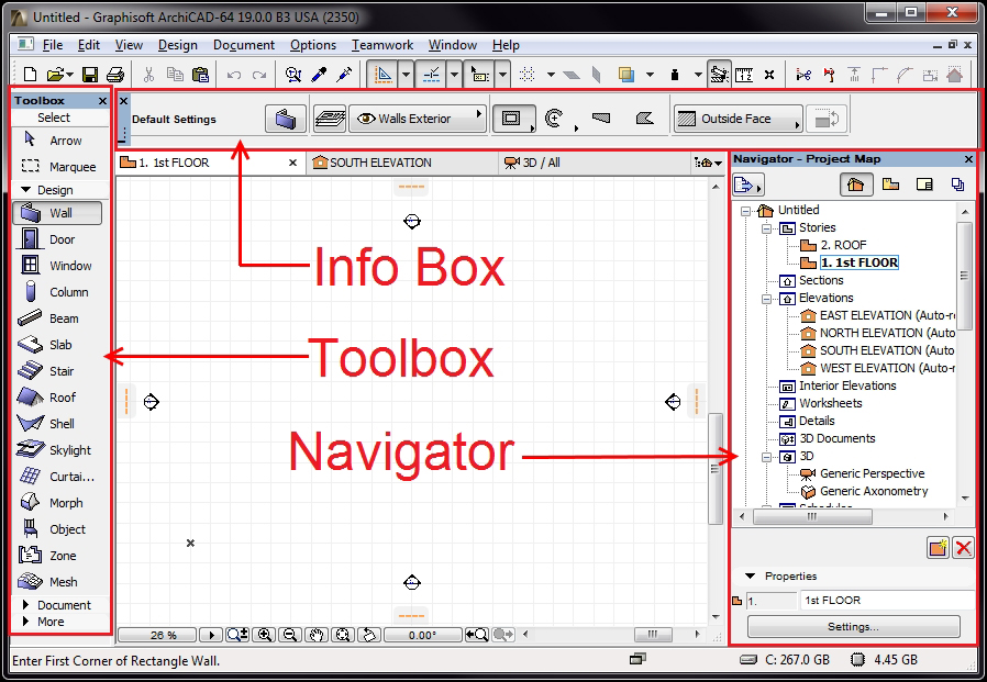
The first time you open ArchiCAD you will find the toolbars along the top, just under the menu bar and there will be palettes docked to the left and right of the drawing area. We will focus on the three following palettes to get started:
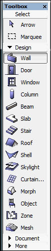
The Toolbox palette: This contains all of your selection, modeling, and drafting tools. It will be located on the left hand side by default.
The Info Box palette: This is your context menu that changes according to whatever tool is currently in use. By default, this will be located directly under the toolbars at the top. It has a scrolling function; hover your cursor over the palette and spin the scroll wheel on your mouse to reveal everything on the palette.
The Navigator palette: This is your project navigation window. This palette gives you access to all your views, sheets, and lists. It will be located on the right-hand side by default.
These three palettes can be seen in the following screenshot:
All of the mentioned palettes are dockable and can be arranged however you like on your screen. They can also be dragged away from the main ArchiCAD interface. For instance, you could have palettes on a second monitor.
ArchiCAD has the same panning and zooming interface as most other CAD (Computer-aided design) and BIM (Building Information Modeling) programs. Rolling the scroll wheel on your mouse will zoom in and out. Pressing down on the scroll wheel (or middle button) and moving your cursor will execute a pan.
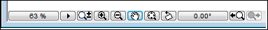
Each drawing view window has a row of zoom commands along the bottom. You should try each one to get familiar with each of their functions.
When you have multiple views open, you can toggle through them by pressing the Ctrl key and tapping on the Tab key. Or, you can pick any of the open views from the bottom of the Window pull-down menu.
Pressing the F2 key will open a 2D floor plan view and pressing the F3 key will open the default 3D view.
Pressing the F5 key will open a 3D view of selected items. In other words, if you want to isolate specific items in a 3D view, select those items and press F5.
ArchiCAD is available in multiple different language versions. The exercises in this book use the USA version of ArchiCAD. Obviously this version is in English. There is another version in English and that is referred to as the International (INT) version. You can use the International version to do the exercises in the book, just be aware that there may be some subtle differences in the way that something is named or designed.
When you create a new project in ArchiCAD, you start by opening a project template. The template will have all the basic stuff you need to get started including layers, line types, wall types, doors, windows, and more.
The following lesson will take you through the first steps in creating a new ArchiCAD project:
Open ArchiCAD.
The Start ArchiCAD dialog box will appear. Select the Create a New Project radio button at the top.
Select the Use a Template radio button under Set up Project Settings.
Select ArchiCAD 19 Residential Template.tpl from the drop-down list. If you have the International version of ArchiCAD, then the residential template may not be available. Therefore you can use ArchiCAD 19 Template.tpl.
Now that you have opened your new project, we are going to create a house with 4 stories (which includes a story for the roof). We create a story for the roof in order to facilitate a workspace to model the elements on that level. The template we just opened only has 2 stories, so we will need to add 2 more. Then we need to look at some other settings.
The settings for the stories are as follows:
-
On the Navigator palette, select the Project Map icon
 .
.
Double click on 1st FLOOR.
Right click on Stories and select Create New Story.
You will be prompted to give the new story a name. Enter the name
BASEMENT.Click on the button next to Below.
Enter
9'into the Height box and click on the Create button. Then double click on 2. 2nd FLOOR.Right click on Stories and then select Create New Story.
You will be prompted to give the new story a name. Enter the name
ROOF.Click on the button next to Above.
Enter
9'into the Height box and click on the Create button.
Your list of stories should now look like this
3. ROOF
2. 2nd Floor
1. 1st Floor
-1. BASEMENT
Tip
The International version of ArchiCAD (INT) will give the first floor the index number of 0. The second floor index number will be 1. And the roof will be 2.
Now we need to adjust the heights of the other stories:
On the menu bar, go to Options | Project Preferences | Working Units and perform the following steps:
Ensure Model Units is set to feet & fractional inches.
Ensure that Fractions is set to 1/64.
Ensure that Layout Units is set to feet & fractional inches.
Ensure that Angle Unit is set to Decimal degrees.
Ensure that Decimals is set to 2.
You are now ready to begin modeling your house, but first let's save the project. To save the project, perform the following steps:
Navigate to the File menu and click on Save. If by chance you have saved it already, then click on Save As.
Name your file
Colonial House.Click on Save.
The Renovation Filter feature allows you to differentiate how your drawing elements will appear in different construction phases. For renovation projects that have demolition and new work phases, you need to show the items to be demolished differently than the existing items that are to remain, or that are new.
The projects we will work on in this book do not require this feature to manage phases because we will only be creating a new construction. However, it is essential that your renovation filter setting is set to New Construction. We will do this in the first modeling exercise.
Pick the Arrow tool from the toolbox or hold the Shift key down on the keyboard and click on what you want to select. As you click on the elements, hold the Shift key down to add them to your selection set. To remove elements from the selection set, just click on them again with the Shift key pressed.
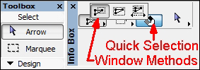
There is a mode within this mode called Quick Selection. It is toggled on and off from the Info Box palette. The icon looks like a magnet. When it is on, it works like a magnet because it will stick to faces or surfaces, such as slabs or fill patterns. If this mode is not on, then you are required to find an edge, endpoint, or hotspot node to select an element with a single click. Hold the Space button down to temporarily change the mode while selecting elements.
Pick the Arrow tool from the toolbox or hold the Shift key down and draw your selection window. Click once for the window starting corner and click a second time for the end corner.
Note
This works just as windowing does in AutoCAD. Not as Revit does, where you need to hold the mouse button down while you draw your window.
There are 3 different windowing methods. Each one is set from the Info Box palette:
Partial Elements: Anything that is inside of or touching the window will be selected. AutoCAD users will know this as a Crossing Window.
Entire Elements: Anything completely encapsulated by the window will be selected. If something is not completely inside the window then it will not be selected.
Direction Dependent: Click and window to the left, the Partial Elements window will be used. Click and window to the right, the Entire Elements window will be used.
A marquee is a selection window that stays on the screen after you create it. If you are a MicroStation CAD program user, this will be similar to a selection window. It can be used for printing a specific area in a drawing view and performing what AutoCAD users would refer to as a Stretch command.
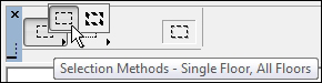
There are 2 types of marquees; single story (skinny) and multi story (fat). The single story marquee is used when you want to select elements on your current story view only. The multi-story marquee will select everything on your current story as well as the stories above and below your selections.
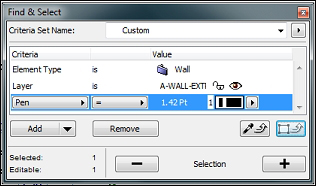
This lets ArchiCAD select elements for you, based on the attribute criteria that you define, such as element type, layer, and pen number. When you have the criteria defined, click on the plus sign button on the palette and all the elements within that criterion inside your current view or marquee will be selected.
As you draw, you will inevitably need to move, copy, stretch, or trim something. Select your items first, and then execute the modification command. Here are the basic commands you will need to get things moving:
Adjust (Extend): Press Ctrl + - or navigate to Edit | Reshape | Adjust
Drag (Move): Press Ctrl + D or…navigate to Edit | Move | Drag
Drag a Copy (Copy): Press Ctrl + Shift + D or navigate to Edit | Move | Drag a Copy
Intersect (Fillet): Click on the Intersect button on the Standard toolbar or navigate to Edit | Reshape | Intersect
Resize (Scale): Press Ctrl + K or navigate to Edit | Reshape | Resize
Stretch: Press Ctrl + H or navigate to Edit | Reshape | Stretch
Trim: Press Ctrl or click on the Trim button on the Standard toolbar or navigate to Edit | Reshape | Trim. Hold the Ctrl key down and click on the portion of wall or line that you want trimmed off. This is the fastest way to trim anything!
We will start with the wall tool to create the main exterior walls on the 1st floor of our house, and then create the floor with the slab tool. However, before we begin, let's make sure your Renovation Filter is set to New Construction.
The Renovation Filter is an active setting that controls how the elements you create are displayed. Everything we create in this project is for new construction so we need the new construction filter to be active.
To do so, go to the Document menu, click on Renovation and then click on 04 New Construction.
The Wall tool has settings for height, width, composite, layer, pen weight and more. We will learn about these things as we go along, and learn a little bit more each time we progress into to the project.
To create the exterior walls of the 1st story perform the following steps:
Select the Wall tool from the Toolbox palette, or from the menu bar under Design | Design Tools | Wall.
Double click on 1. 1st Story in the Navigator palette to ensure that we are working on story 1.
Select the Wall tool from the Toolbox palette, or from the menu bar under Design | Design Tools | Wall.

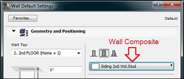
Change the composite type to be Siding 2x6 Wd. Stud. Click on the wall composite button to do this.
Notice at the bottom of the Wall Default Settings window is the layer currently assigned to the wall tool. It should be set to A-WALL-EXTR.
Click on OK to start your first wall.
Click near the center of the drawing screen and move your cursor to the left, notice the orange dashed line that appears. That is your guide line. Keep your cursor over the guide line so that it keeps you locked in the orthogonal direction. You should also immediately see the Tracker palette pop up, displaying your distance drawn and angle after your first click. Before you make your second click, enter the number
24from your keyboard and press Enter. You should now have 24-0" long wall.Select this again and make your first click on the upper left end corner of your first wall. Move your cursor down, so that it snaps to the guideline, enter the number
28, and press the Enter key.Draw your third wall by clicking on the bottom left endpoint of your second wall, move your cursor to the right, snapped over the guide line, type in the number
24and press Enter.Draw your fourth wall by clicking on the bottom right end point of your third wall and the starting point of your first wall. You should now have four walls that measure 24'-0" x 28"-0, outside edge to outside edge.
Move your four walls to the center of the drawing view and perform the following steps:
a. Click on the Arrow tool at the top of the Toolbox.
b. Click outside one of the corners of the walls, and then click on the opposite side. All four walls should be selected now.
c. Use the
Dragcommand to move the walls. The quickest way to activate theDragcommand is by pressing Ctrl + D. The long way is from the menu bar by navigating to Edit | Move | Drag.d. Drag (move) the walls to the center of your drawing window.
e. Press the Esc key or click on a blank space in your drawing window to deselect the walls.

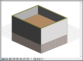
You are now ready to create a floor with the slab tool. But first, let's have a little fun and see how it looks in 3D (press the F3 key):
From the Navigator palette, double click on Generic Axonometry under the 3D folder icon.
This will open a 3D view window. Hold your Shift key down, press down on your scroll wheel button, and slowly move your mouse around. You are now orbiting!
Play around with it a little, then get back to work and go to the next step to create your first floor slab. Press the F2 key to get back to a 2D view.
The slab tool is used to create floors. It is also used to create ceilings. We will begin using it now to create the first floor for our house. Similar to the Wall tool, it also has settings for layer, pen weight and composite. To create the first story's floor using the Slab tool, perform the following steps:
Select the Slab tool from the Toolbox palette or from the menu bar under Design | Design Tools | Slab.
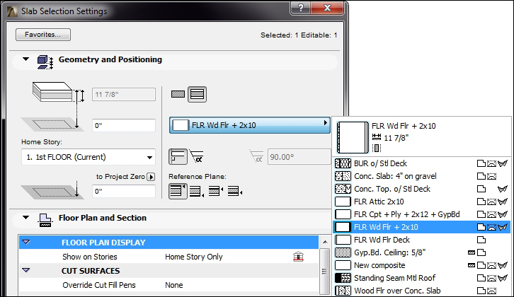
This will change the contents of the Info Box palette. Click on the Slab icon in Info Box. This will bring up the Slab Default Settings (active properties) window for the Slab tool.
As with the Wall tool, you have a composite setting for the slab tool. Set the composite type for the slab tool to FLR Wd Flr + 2x10.
The layer should be set to A-FLOR.
Click OK.
You could draw the shape of the slab by tracing over the outside lines of your walls but we are going to use the Magic Wand feature. Hover your cursor over the space inside your four walls and press the space bar on your keyboard. This will automatically create the slab using the boundary created by the walls. Then, open a 3D view and look at your floor.
We could repeat all of the previous steps to create the floor and walls for the second story and the basement, but in this case, it will be quicker to copy what we have already drawn on the first story and copy it up with the Edit Elements by Stories tool. Perform the following steps to create the exterior walls and floor slabs for the basement and second story:
Go to the Navigator palette and right click over Stories, select Edit Elements by Stories. The Edit Elements by Stories window will open.
Under Select Action, you want to set it to Copy.
Under From Story, set it to 1. 1st FLOOR.
In the To Story section, check the box for 2nd FLOOR and -1. BASEMENT.
Click on OK.
You should see a dialog box appear, stating that as a result of the last operation, elements have been created and/or have changed their position on currently unseen stories. Whenever you get this message, you should confirm that you have not created any unwanted elements.
The floor and the walls on the BASEMENT story need to be changed to a different composite type. Do this by performing the following steps:
Open the BASEMENT view and select the four walls by clicking on one at a time while holding down the Shift key.
Right click over your selection and click on Wall Selection Settings. Change the walls to the EIFS on 8" CMU composite type. Then, click on OK.
Move your cursor over the floor slab. The quick selection cursor should appear. This selection mode allows you to click on an object without needing to find an edge or endpoint. Click on the slab.
Open the Slab Selection Setting window but this time, do it by pressing the Ctrl + T key combination. Change the floor slab composite to Conc. Slab: 4" on gravel. Click on OK.
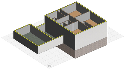
Open a 3D view (by pressing the F3 key) and orbit around your house. It should look similar to the following screenshot:
We need to add the garage and the laundry room, which connects the garage to the house. Do this by performing the following steps:
Open the 1st FLOOR story from the project map.
Start the Wall tool. From the Info Box palette, set the wall composite setting to Siding 2x6 Wd. Stud.
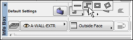
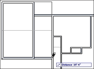
Click on the upper-left corner of your house for your wall starting point. Move your cursor to the left, snap to the guide line, type
6'-10", and press Enter.Change the Geometry Method setting on Info Box to Chained. Refer to the following screenshot:
Start your next wall by clicking on the endpoint of your last wall, move your cursor up, snap to the guideline and type 5', and press Enter.
Move your cursor to the left, snap to grid line, type in
12'-6", and press Enter.Move your cursor down, snap to grid line, type in
22'-4", and press Enter.Move your cursor to the right, snap to grid line and double click on the perpendicular west wall (double pressing your Enter key will work the same as a double click).
Now we want to create the floor for this new set of walls. To do that, perform the following steps:
Start the Slab tool.
Change the composite to Conc. Slab: 4" on gravel.
Hover your cursor inside the new set of walls and press the Space key to use the magic wand. This will create the floor slab for the garage and laundry room.
There is still one more wall to create, but this time we will use the Adjust command to, in effect, create a new wall:
Select the 5'-0" wall drawn in the previous exercise.
Go to the Edit menu, click on Reshape, and then click on Adjust.
Click on the bottom edge of the perpendicular wall down below. The wall should extend down. Refer to the following screenshot:

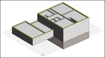
Then Change to a 3D view (by pressing F3) and examine your work.
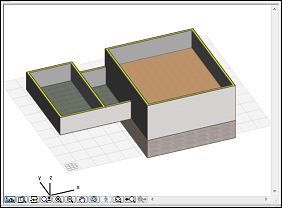
The 3D view
Now we are ready to create the interior walls. Open the 1st FLOOR view from the project map, and perform the following steps:

We are going to create the interior walls on the second floor. Some of the walls on the second story align with walls on the first story. We will use the Trace and Reference feature to display the walls on the story below. Revit users will know this as the underlay property of the view.
Open the 2nd FLOOR view and go to the View menu, click on Trace to toggle on the Trace mode. This should display the floor below in a halftone by default. The image that follows shows the second floor walls to be drawn and the wall below in a halftone.
Tip
Other ways to toggle the Trace mode on and off are with the keyboard combination Ctrl + F2, the Trace button on the Standard toolbar, and the button on the Trace and Reference palette.
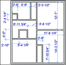
Draw the walls of the second floor according to the dimensions shown in the following diagram. Use the locations of the wall below as a guide for the second floor walls that are aligned.
Open a 3D view. It should look like the image that follows:
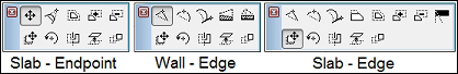
Another way to modify something is to use the pet palette. After you select an item, click on an endpoint or edge of that element. This will bring up the pet palette for that type of element. The pet palette is essentially an on-demand toolbar that is specifically designed for the type of element you select. It can have commands such as move, rotate, stretch, etc. Following are a few examples according to element type and what part of the element is clicked on.
All the walls and floors in our house are drawn. Now it is time for us to model the ceilings. This house has typical gypsum board ceilings at 8'-0" above the finished floor. We will put them in the first and second floor stories. The basement ceiling will be exposed to the floor above.
First, we need to create a composite for a 5/8" gypsum board to be used by the slab tool as the ceiling material.
Perform the following steps to create a composite type:
On the menu bar navigate to Options | Element Attributes | Composites. The Composite Structures window will open. Click on the New button.
Enter
Gyp.Bd. Ceiling: 5/8"as the name.Change the building material to Gypsum Board and the thickness to 5/8".
This composite is designed to be used for slabs and walls. At the bottom right, click on the Roof and Shell buttons so they are un-selected, leaving the Wall and Slab tool selected.

We will start modeling the ceilings on the first floor by drawing slabs in every room except the garage and the stairwell. However, before we start modeling the ceilings, we need to assign a composite type to the ceiling.
Open the 1st FLOOR viewpoint from project map on the Navigator palette. Start the Slab tool from the Toolbox palette.
On the Info Box palette, change the composite to Gyp.Bd. Ceiling: 5/8".
Change the layer to A-CLNG.
Set the Reference level to Height and Home Offset. In the height offset box, enter
8'-0".Use the Magic Wand (Space) and click inside each room one at a time. This will create a 5/8" gypsum board ceiling inside each room at a height of 8'-0".

The skinny room on the first floor to the left is where the stairs to the second floor are going to be. The ceiling over this area needs to be modified to match the wall above on the second floor.
Turn on the Trace feature from the standard toolbar. Click on the down arrow at the right of the Trace button. Choose Reference | Above current story.
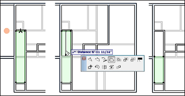
Select the ceiling, click on the top edge and drag it down to the first edge of the wall above. Refer to the following sequence of images:
Now we are ready to create the ceilings on the second floor. Perform the following steps:
Open the 2nd FLOOR viewpoint from the Project Map.
Start the slab tool. Keep the same settings used for the 1st floor. Use the Magic Wand (spacebar) to create a ceiling in every room on the 2nd floor.
Open a 3D view to check your work.
You are now ready to model two gable style roofs for our house. One roof over the garage and laundry room, and the second over the second floor. The Roof tool is very dynamic; it can create a complete gable or hip style roof in one step. Or you can create separate individual panels.
The following exercise will step you through the creation of your first roofs!
Open the 1st FLOOR view and start the Roof tool from the tool box.
Change Construction Method to Rotated Rectangular Hip/Gable. Change the overhang offset to
1'-0". Look at the following image:
This construction method requires 3 clicks. Select the upper-left corner of the garage, then click on the bottom left corner, and then the bottom-right hand corner. Refer to the following image:
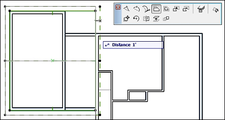
The overhang on the right edge is penetrating the second floor and needs to be pulled back. Select the roof, click on the right edge (the pet palette will pop up, the offset edge button will be selected), then drag the edge over to the edge of the wall to the left. Take a look at the following image:
Open the 2nd FLOOR view. Click on the Roof tool; use the same method as before. Click on the upper left corner of the second floor wall, then click on the lower left corner, and then on the lower right corner.
You now have 2 roofs, but the pitch needs to be adjusted for our house's design:
Open the WEST ELEVATION viewpoint from Project Map
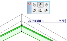
Select one of the roofs. Click on the top point and hold the cursor down so the pet palette pops up.
Click on the Elevate Horizontal Ridge button from the pet palette. Drag your cursor up, enter
1from your keyboard and press Enter. This should bring up the ridge by 1'-0".Repeat steps 2 and 3 for the other roof.
Open a 3D view. You will see that your roofs are added but there is a gap at the gable ends that needs to be filled.
Your task is to change the height of the 3 walls that will fill the gable end of each roof, then trim the walls using the roofs as a cutting plane:
Open the 3D window, orbit to the west side of the house and select the west wall of the garage.
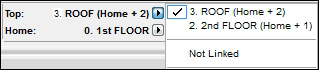
With the wall selected, go to the Info Box palette and change the Top setting to 3. Roof. Use the following image as a guide:
Right-click on wall (the wall is still selected), from the right-click menu select Connect… | Trim Elements to Roof/Shell.
a. Click on the roof over the garage to use it as your trim element.
b. Click on the lower portion of the wall to select what part to keep.
c. Click on a blank area of the screen to complete the command.
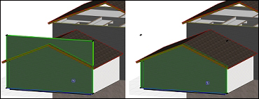
Next, you want to do the same to the second floor walls at the gable ends of the second floor roof. However, this time when you change the height of the wall, the process is different because there is no story above 3. Roof.
Perform the following steps to trim the second story walls to the second story roof. When finished, your exterior walls will be complete.
Select one of the second floor walls that need to be trimmed to the second floor roof. From the Info Box palette, change the Bottom and Top setting to Top and Home Offsets. Set the top height to
9'-0". Refer to the following image: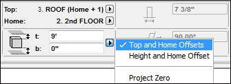
Select the same wall and right click on it. From the right-click menu select Connect… | Trim Elements to Roof/Shell.
a. Click on the roof over the second floor to use as your trim element.
b. Click on the lower portion of the wall to select what part to keep.
c. Click on a blank area of the screen to complete the command.
Repeat steps 1 and 2 for the other second floor wall.

There is a portion of the roof over the garage that will need to have a piece cut out of it. It is the area above the back door of the laundry room. ArchiCAD makes it easy to cut holes out of roof objects. You will start by activating the Roof tool, then select the roof and draw the portion of the roof to be subtracted. To demonstrate this feature, perform the following steps.
Open 1st FLOOR from the project map.
Start the Roof tool, then hold the Shift key down and select the roof over the garage (it is vital that you start the Roof tool before you select the roof).
Click on the outside corner of where the east garage wall and the North house wall intersect. Make your second click at the end of the wall, where it intersects with the west wall of the house. Drag your cursor up past the edge of the overhang and click. This should create the notch as shown in the following images:

The first step in cutting the notch in the roof

The second step in cutting the notch in the roof

We have briefly touched upon using layers in the steps leading to this point. As we go further, you will need to learn how to manage your layers. We will go deep into layer management in later portions of this book, but we will have a quick primer on layers to keep you productive.
Similar to how layers work in CAD programs, you can turn them on, off, and lock them. Any element is subject to the on/off/lock status of the layer it is placed on. However, layers in ArchiCAD do not control elements the same way as they do in AutoCAD or MicroStation.
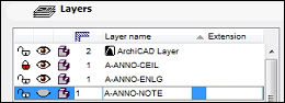
Open the Layer Settings manager window with a Ctrl + L key combination. Or you could also open it from the menu bar by navigating to Document | Layers | Layer Settings.
Look at the screenshot taken from the layer settings manager. You will see the eyeball icon column; it shows the layer (on) or hides the layer (off). The concept for the lock icon is the same. We will discuss the other columns later in the book.
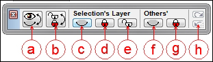
The Quick Layers palette is an excellent tool for performing quick little layer tasks such as hiding the layer of a selected object, hiding all the layers that your selected object is on, or locking a selected item's layer. See the features list, palette, and legend notes that follow:
a. Toggle between shown and hidden layers
b. Toggle between unlocked and locked layers
c. Hide the selection's layer(s)
d. Lock the selection's layer(s)
e. Unlock the selection's layer(s)
f. Hide all layers other than the ones selected (isolate selected objects' layers)
g. Lock all the layers not selected
h. Undo and Redo for any of the commands executed on the Quick Layers palette. Lock all layers other than the ones selected
All of the major modeling tasks have been completed. But the house is floating in space and we need to put it on something. So, let's start on creating the site. We will use the Mesh command to create the terrain for the house to sit on:
Open 1st FLOOR from the project map.
From Toolbox, click on the Mesh tool.
Change the construction method to rectangle.
Create a 150' x 150' rectangle to surround the house: after your first click point, enter
150on the keyboard, then press the Tab key and enter150again, then press Enter. This will create a site mesh. Select the mesh, then drag and center it around the house.You need to cut a hole in the mesh to accommodate the basement. Click on the Mesh tool icon again and select the mesh that you just created.
Click on the upper-right outside corner of the house, then with your second pick, click on the exterior left front corner of the house. A window will pop up for specifying new mesh points. Select the radio button for Create Hole. Leave the fit specification as Fit to User Ridges. Click on OK.
Let's go back inside the house and add the room elements, known as zones. Zones contain information that feeds room tags and provides data that can be used for BIM data extraction.
We need to add zones to all the room spaces. The following steps will walk you through the process by starting at the bottom story, in the basement:
Open BASEMENT from the project map.
Start the Zone tool from Toolbox. On the Info Box palette, do the following:
a. Set the construction method to Rectangular.
b. Enter the name BASEMENT in the room name box.
c. Enter
001in the room number box.
Click on the top left inside corner of the basement room and then on the lower right hand inside corner. Then click on the center of the room (the hammer icon will appear). You should now see a room tag that has the room name, number, and area.
Open the Layer Settings manager (Ctrl + L) and hide the following layers: A-CLNG, A-FLOR, A-ROOF, and L-SITE. This will keep us from accidently selecting items on those layers, or you could lock them instead.
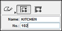
Open the 1st FLOOR from the project map and start the Zone tool. On the Info Box palette, click on the Floor Plan Contour Line icon to turn it on, and set the pen to
5. Change Construction Method to Polyline.
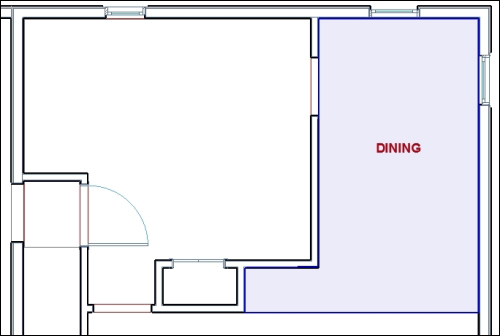
Change the name in the Name box to DINING. Draw the zone boundary of the DINING room according to the following diagram:
Change the name in the Name box to KITCHEN. Change the construction method to Inner Edge. Click inside the kitchen room and the zone will automatically find the walls and use them as a boundary.
Finish the remaining rooms on the first floor (shown in the following diagram) with any of the construction methods used previously.
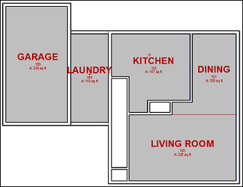
Floor plan of the first floor
Do the same for the rooms on the second floor according to the image of the second floor that follows:
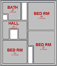
Floor plan of the second floor
Now that you have created most of your rooms, you may want to know the square footage of each one and see them in a list. Go to the project map and scroll down to Lists. Expand Lists by clicking on the plus sign, then expand Zones.
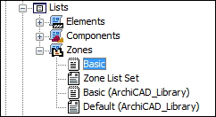
Double click on Basic. This will open a list of all the zones you just created. Refer to the following screenshot:
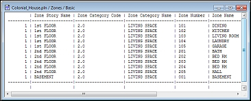
The list of created zones
Notice that all the rooms are in the LIVING SPACE zone category. This is not what we want for Garage, or Laundry Room, or probably even the BASEMENT. Perform the following steps to change the category of the zones that we don't want in the LIVING SPACE category.
Open 1st FLOOR. and select the GARAGE zone.
In Info Box change the zone category from 2.0 LIVING SPACE to 3.1 Garage.
Select the LAUNDRY zone and change the zone category to 3.0 UTILITY.
Select the BASEMENT zone and change the zone category to 2.2 Unconditioned Space.
You are almost done with inserting your zones. All that is left to do is to add zones for the closets and the stairs from the first floor to the second floor.
Open 2nd FLOOR.
Start the Zone tool and set the zone category to 0.10 Storage. Change the room name to CLOSET. The value for Construction Method is set to Inner Edge.
Create a zone inside each one of the empty rooms on the second floor. The room numbers will start from where you left off on the second floor before.
Open 1st FLOOR. Change the room number in the Info Box to 106. Create a zone inside the small rectangle room at the top of the living room, and do the same for the small room on the lower-left side of the living room.
Set the zone category in the Info Box to 2.0 LIVING SPACE. Change the room name to STAIRS. Click inside the remaining empty space above the front closet.
It is time for us to start adding doors to our house. If you have used CAD for as long time you will quickly learn to love how doors work inside of ArchiCAD. When you place a door, it will automatically attach itself to a wall. From there you can move the door along the wall and the line work will automatically cleanup. Within each door object are parameters that can control size and appearance.
Before you begin, hide the following layers: A-AREA-IDEN, A-ROOF. This will make it easier to work on our doors. Perform the following steps:
Let's start on the first floor. Click on the Door tool inside the Toolbox palette. Look at the Info Box palette and D1 Entrance 19 should be the default door that is ready to be inserted.
Zoom in on the southwest corner of the house. Hover your cursor over the bottom edge of the south exterior wall, which is just to the right of the front closet. You will see the Mercedes cursor and an outlined representation of the door opening appear, along with a sun symbol that signifies the exterior side of the door. Click once on the wall to place the door in it.

As you move your cursor around you will see how it changes where the door leaf will be placed. Click on it one more time when you have the door opening outside to the left. Notice how a door tag is automatically inserted.

Insert another door in the upper-left corner of the laundry room.
You have now placed your first two doors. They are exterior doors, so now we need to place interior doors and openings. We will continue working on the first floor:
Double click on the Door tool icon inside the Toolbox palette. This will open the Default Door Settings window. In the library pane on the upper left, under Linked Libraries, click on Empty Door Openings 19 folder. Click on Arch Top Door Opening 19. Click on the OK button.

Place a door opening at the bottom of the stairs, and two in the kitchen.
Double click on the Door tool icon again to change the door type to D1 Garage 2 19, from under 08 30 00 Specialty Doors and Frames 19\Garage Doors 19. Place the garage door at the center of the south wall of the garage.
Double click on the Door tool icon to change the door type to D1 19 from under 08 11 00 Wood Doors 19\Wood Internal Doors 19. Insert the door in the kitchen by the laundry room.
Double click on the Door tool icon to change the door type to D1 Bifold 19 from under 08 30 00 Specialty Doors and Frames 19\Bifold Doors 19. Insert the door at the closet at the bottom of the stairs and the closet in the Kitchen. In the Info Box palette, change the door opening width to
2'-6". Refer to the screenshot of Info Box that follows:
Open the second floor. Double click on the Door tool icon to change the door type to D1 19 from under 08 11 00 Wood Doors 19\Wood Internal Doors 19. Insert doors for all 3 bedrooms and the bathroom.
Using the same settings as discussed in the preceding step, change the door width to
1'-8", and place a door in the bathroom for the closet.Double click on the Door tool icon to change the door type to Sliding Folding Multipanel Door 19 from under Sliding Folding Doors 19. Change the width to
5'-0". Insert doors for the long closet in the 2 bedrooms on the right. Refer to the images that follow to check your work:
1st Floor 2nd Floor
Similar to doors, windows automatically snap to walls and have changeable parameters that control size and appearance. But it is important to note that doors and windows require a wall to act as a host because they cannot exist on their own. This means that the door and windows assume the layer of the wall. This is why you don't see a layer setting in Info Box when the window or door tool is active.
Let's add windows to our house, starting on the first floor:
Start the Window tool from the Toolbox palette. The default settings should be door W Double Hung 19, width
2'-6", height5'. Look at the image of the Info Box palette that follows: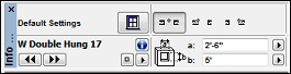
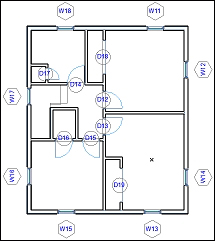
Use the following plan as a guide and place 2 windows in the living room, 2 in the dining room, 1 in the kitchen, 1 in the laundry room, and 1 in the garage. Placing windows works just like placing doors, refer to steps 2 and 3 in the Doors exercise done earlier.

Open the second floor. Using the same settings as we used earlier, place windows in each room according to the following image.
The layout for the second floor
The Stair tool is a tool that involves a good amount of setup before you actually place a stair, because stairs are always unique and contain many components. For our project we need 2 stairs. One to get to the 2nd floor from the first floor and one to get to the basement from the first floor.
Before we get started, we will want to alter our view to give us a better view. Specifically, we want to turn off the window and door tags. We will do this by changing the current model view options:
Go to the menu bar, navigate to Document | Set Model View | Model View Options.
Select the Presentation-Solid model view option combination.
Click on OK.
Perform the following steps to create your first stair:
Open the basement viewpoint from the project map on the Navigator palette. Toggle on the Trace feature from the Standard tool bar at the top of your screen. Turn on the first floor for tracing.
a. Click the drop down portion of the Trace button, and select Reference | Above Current Story.
Start the Stair tool. Set the construction method to Diagonal and the Home story to -1. BASEMENT on the Info Box palette.
Click on the Stair icon to open the Stair Default Setting window. Change the stair type to Stair Straight 19. Then, go to the Preview and Position section. Then, perform the following steps:
a. Rotate the preview to match the image that follows.
b. Set the insertion point to the lower right corner of the stair.
c. Uncheck the Mirror Library Part box.
d. Change the height to
9'. Click on OK.
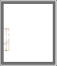
You will make two clicks to define the width and length of the stair. Click on the inside corner of the opening above for your first click and the bottom edge of the door above, as per the image that follows:

Toggle off the trace and your plan should look similar to the following image.
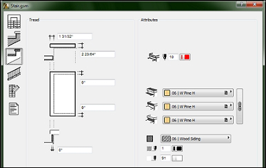
Click on the Structure and Landing settings button on the left-hand side.
a. Change all four surface materials under Attributes to 06 | W Pine H.
b. Change the section fill to vectorial fill 06 | Wood Siding.

Click on the Tread Settings button on the left.
a. Change all three surface materials under Attributes to 06 | W Pine H.
b. Change the section fill to vectorial fill 06 | Wood Siding.
c. Click on the Railing Settings button on the left-hand side.
d. Change the Railing Setting selection to No railing.
e. Click on the Symbol Settings button to the left.
f. Change the 2D Detail Level type to Type 9.
g. Click on OK. The Save Stair window will open, prompting you to name your new stair. Enter the name
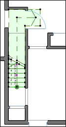
Stair Custom 1and click on Save.Click on the 1st Floor plan view to insert the stair. Then, drag it into position as shown in the following diagram:
The stair going up to the second floor is not of a typical design. It is an L-shaped stair with a landing. The landing is at the top and the L portion is only 2 risers. In this situation we will use the Create Stair tool to create a new stair object. Perform the following steps to create your second stair:
Open the 1st FLOOR view. Click on the Stair tool icon in the Toolbox palette. Then from the Info Box palette, click on the Create Stair button.
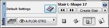
Select L-Run with Landing. Click on OK.

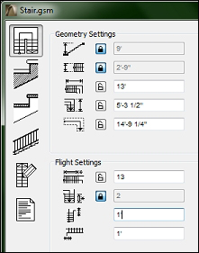
This will open a settings window. The Geometry and Flight settings will be shown. Make the following changes:
a. Total height:
9'| push the lock button.b. Flight width:
2'-9"| push the lock button.c. Lower part length:
13'.d. Number of risers of the lower side to
13.e. Number of risers of the upper side to
2| push the lock button.f. Offset of lower walking:
1'.g. Offset of upper walking:
1'.
In order for the stairs to get from the first floor to the second floor, you will need to cut a hole in the floor slab on the second floor. Now that you have modelled all the interior walls, you have a template to use as a guide to make the hole.
Open the 2nd Floor viewpoint from the project map. Toggle on the Trace feature and change the reference to 1st Floor.
Make sure the bathroom entry door is placed at the far right, up against the wall.
Start the Slab tool and then select the floor slab (it is vital that the Slab tool is active while the slab is selected). Change the construction method to Polygon.
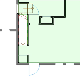
In this step we will define the boundary of the hole to be cut in the slab. Make your first click on the bottom edge of the bathroom wall, where it intersects the stair below. Trace the outline of the stair below and along the edge of the second floor walls as shown in the following diagram. Toggle off the Trace feature and your floor should as in the following diagram:

Do the same for the floor on the first floor according to the diagram that follows. This will allow access to the basement stair to reach the first floor.
In this chapter you were introduced to the ArchiCAD Graphical User Interface (GUI), project settings and learned how to select stuff. You created all the major modeling for your house and got a primer on layers. Now you should have a good understanding of the ArchiCAD way of creating architectural elements and how to control their parameters. In the next chapter you will be introduced to objects such as casework, plumbing fixtures, and furniture; as well as the drafting and annotation tools.