


Basics of Agile Systems Modeling
For the most part, this book is about systems modeling with SysML, but doing it in an agile way. Before we get into the detailed practices of systems modeling with that focus, however, we’re going to spend some time discussing important project-related agile practices that will serve as a backdrop for the modeling work.
Almost all of the agile literature focuses on the “three people in a garage developing a simple application” scope. The basic assumptions of such projects include:
- The end result is software that runs on a general-purpose computing platform (i.e., it is not embedded).
- Software is the only truly important work product. Others may be developed but they are of secondary concern. Working software is the measure of success.
- The software isn’t performance, safety, reliability, or security-critical.
- It isn’t necessary to meet regulatory standards.
- The development team is small and co-located.
- The development is time-and-effort, not fixed-price cost.
- The development is fundamentally code-based and not model- (or design)-based.
- Any developer can do any task (no specialized skills are necessary).
- Formalized requirements are not necessary.
Yes, of course, there is much made about extensions to agile practices to account for projects that don’t exactly meet these criteria. For example, some authors will talk about a “scrum of scrums” as a way to scale up to larger teams. That works to a point, but it fails when you get to much larger development teams and projects. I want to be clear – I’m not saying that agile methods aren’t application to projects that don’t fall within these basic guidelines – only that the literature doesn’t address how it will do so in a coherent, consistent fashion. The further away your project strays from these assumptions, the less you will find in the literature for agile ways to address your needs.
In this book, we’ll address a domain that is significantly different than the prototypical agile project. Our concerns will be projects that:
- Are systems-oriented, which may contain software but will typically also contain electronic and mechanical aspects. It’s about the system and not the software.
- Employ a Model-Based Systems Engineering (MBSE) approach using the SysML language.
- May range from small- to very large-scale.
- Must develop a number of different work products. These include, but are not limited to:
- Requirements specification
- Analysis of requirements, whether it is done with use case or user stories
- System architectural specification
- System interface specification
- Trace relations between the elements of the different work products
- Safety, reliability, and security (and resulting requirements) analyses
- Architectural design trade studies
- Have a handoff to downstream engineering that includes interdisciplinary subsystem teams containing team members who specialize in software, electronics, mechanical, and other design aspects.
But at its core, the fundamental difference between this book and other agile books is that the outcome of systems engineering isn’t software, it’s system specification. Downstream engineering will ultimately do low-level design and implementation of those specifications. Systems engineering provides the road map that enables different engineers with different skill sets, working in different engineering disciplines, to collaborate together to create an integrated system, combining all their work into a cohesive whole.
The International Council of Systems Engineering (INCOSE) defines systems engineering as “a transdisciplinary and integrative approach to enable the successful realization, use, and retirement of engineered systems, using systems principles and concepts, and scientific, technological, and management methods” (https://www.incose.org/about-systems-engineering/system-and-se-definition/systems-engineering-definition). This book will not provide a big overarching process that ties all the workflows and work products together, although it is certainly based on one. That process – should you be interested in exploring it – is detailed in the author’s Agile Systems Engineering book; a detailed example is provided with the author’s Harmony aMBSE Deskbook, available at www.bruce-douglass.com. Of course, these recipes will work with any other reasonable MBSE process. It is important to remember that:
The outcome of software development is implementation;
The outcome of systems engineering is specification.
What’s agile all about?
Agile methods are – first and foremost – a means for improving the quality of your engineering work products. This is achieved through the application of a number of practices meant to continuously identify quality issues and immediately address them. Secondarily, agile is about improving engineering efficiency and reducing rework. Let’s talk about some basic concepts of agility.
Incremental development
This is a key aspect of agile development. Take a big problem and develop it as a series of small increments, each of which is verified to be correct (even if incomplete).
Continuous verification
The best way to have high-quality work products is to continuously develop and verify their quality. In other books, such as Real-Time Agility or the aforementioned Agile Systems Engineering books, I talk about how verification takes place in three timeframes:
- Nanocycle: 30 minutes to 1 day
- Microcycle: 1–4 weeks
- Macrocycle: Project length
Further, this verification is best done via the execution and testing of computable models. We will see in later chapters how this can be accomplished.
Continuous integration
Few non-trivial systems are created by a single person. Integration is the task of putting together work products from different engineers into a coherent whole and demonstrating that, as a unit, it achieves its desired purpose. This integration is often done daily, but some teams increment this truly continuously, absorbing work as engineers complete it and instantly verifying that it works in tandem with the other bits.
Avoid big design up front
The concept of incremental development means that one thing that we don’t do is develop big work products over long periods of time and only then try to demonstrate their correctness. Instead, we develop and verify the design work we need right now, and defer design work that we won’t need until later. This simplifies the verification work and also means much less rework later in a project.
Working with stakeholders
A key focus of the Agilista is the needs of the stakeholders. The Agilista understands that there is an “air gap” between what the requirements say and what the stakeholder actually needs. By working with the stakeholder, and frequently offering them versions of the running system to try, they are more likely to actually meet their needs. Additionally, user stories – a way to organize requirements into short usage stakeholder-system usage scenarios – are a way to work with the stakeholder to understand what they actually need.
Model-Based Systems Engineering (MBSE)
Systems engineering is an independent engineering discipline that focuses on system properties – including functionality, structure, performance, safety, reliability, and security. MBSE is a model-centric approach to performing systems engineering. Systems engineering is largely independent of the engineering disciplines used to implement these properties. Systems engineering is an interdisciplinary activity that focuses more on this integrated set of system properties than on the contributions of the individual engineering disciplines. It is an approach to developing complex and technologically diverse systems. Although normally thought of in a V-style process approach (see Figure 1.1), the “left side of the V” emphases the specification of the system properties (requirements, architecture, interfaces, and overall dependability), the “lower part of the V” has to do with the discipline-specific engineering and design work, and the “right side of the V” has to do with the verification of the system against the specifications developed on the left side:

Figure 1.1: Standard V model life cycle
Of course, we’ll be doing things in a more agile way (Figure 1.2). Mostly, we’ll focus on incrementally creating the specification work products and handing them off to downstream engineering in an agile way:

Figure 1.2: Basic Agile systems engineering workflow
The basis of most of the work products developed in MBSE is, naturally enough, the model. For the most part, this refers to the set of engineering data relevant to the system captured in a SysML model. The main model is likely to be supplemented with models in other languages, such as performance, safety, and reliability (although you can use SysML for that too – we’ll discuss that in Chapter 2, System Specification—Functional, Safety and Security Analysis). The other primary work product will be textual requirements. While they are imprecise, vague, ambiguous, and hard to verify, they have the advantage of being easy to communicate. Our models will cluster these requirements into usage chunks – epics, use cases, and user stories – but we’ll still need requirements. These may be managed either as text or in text-based requirements management tools, such as IBM DOORS™, or they can be managed as model elements within a SysML specification model.
Our models will consist of formal representations of our engineering data as model elements and the relationships among them. These elements may appear in one or more views, including diagrams, tables, or matrices. The model is, then, a coherent collection of model elements that represent the important engineering data around our system of interest.
In this book, we assume you already know SysML. If you don’t, there are many books around for that. This book is a collection of short, high-focused workflows that create one or a small set of engineering work products that contain relevant model elements.
Now, let’s talk about some basic agile recipes and how they can be done in a model-centric environment.
Managing your backlog
The backlog is a prioritized set of work items that identify work to be done. There are generally two such backlogs. The project backlog is a prioritized list of all work to be done in the current project. A subset of these is selected for the current increment, forming the iteration backlog. Since engineers usually work on the tasks relevant to the current iteration, that is where they will go to get their tasks. Figure 1.3 shows the basic idea of backlogs:

Figure 1.3: Backlogs
The work to be done, nominally referred to as work items, is identified. Work items can be application work items (producing work that will be directly delivered) or technical work items (doing work that enables technical aspects of the product or project). Work items identify work to do such as:
- Analyzing, designing, or implementing an epic, use case, or user story, to ensure a solid understanding of the need and the adequacy of its requirements
- Creating or modifying a work product, such as a requirements specification or a safety analysis
- Arranging for an outcome, such as certification approval
- Addressing a risk, such as determining the adequacy of the bus bandwidth
- Removing an identified defect
- Supporting a target platform, such as an increment with hand-built mechanical parts, lab-constructed wire wrap boards, and partial software
The work items go through an acceptance process, and if approved, are put into the project backlog. Once there, they can be allocated to an iteration backlog.
Purpose
The purpose of managing your backlog is to provide clear direction for the engineering activities, to push the project forward in a coherent, collaborative way.
Inputs and preconditions
The inputs are the work items. The functionality-based work items originate with one or more stakeholders, but other work items might come from discovery, planning, or analysis.
Outputs and postconditions
The primary outputs are the managed project and iteration backlogs. Each backlog consists of a set of work items around a common purpose, or mission. The mission of an iteration is the set of work products and outcomes desired at the end of the iteration. An iteration mission is defined as shown in Figure 1.4:

Figure 1.4: Iteration mission
In a modeling tool, this information can be captured as metadata associated with tags.
The term “metadata” literally means “data about data”; in this context, we add metadata to elements using tags.
How to do it
There are two workflows to this recipe. The first, shown in Figure 1.5, adds a work item to the backlog. The second, shown in Figure 1.6, removes it:

Figure 1.5: Add work item

Figure 1.6: Resolve work item
Create a workflow item
From the work to be done, a work item is created to put into the backlog. The work item should include the properties shown in Figure 1.7:

Figure 1.7: Work item
- Name.
- Description of the work to be done, the work product to be created, or the risk to be addressed.
- The acceptance criteria – how the adequacy of the work performed, the work product created, or the outcome produced will be determined.
- The work item classification identifies the kind of work item it is, as shown on the left side of Figure 1.3.
- The work item’s priority is an indication of how soon this work item should be addressed. This is discussed in the Prioritize work item step of this recipe.
- The estimated effort is how much effort it will take to perform the task. This can be stated in absolute terms (such as hours) or relative terms (such as user story points). This topic is addressed in the Estimating effort recipe later in this chapter.
- Links to important related information, such as standards that must be met, or sources of information that will be helpful for the performance of the work.
Approve work item
Before a work item can be added, it should be approved by the team or the project leader, whoever is granted that responsibility.
Prioritize work item
The priority of a work item determines in what iteration the work will be performed. Priority is determined by a number of factors, including the work item’s criticality (how important it is), its urgency (when it is needed), the availability of specialized resources needed to perform it, usefulness to the mission of the iteration, and risk. The general rule is that high-priority tasks are performed before lower-priority tasks. This topic is covered in the Work item prioritization recipe later in this chapter.
Estimate effort
An initial estimate of the cost of addressing the work item is important because as work items are allocated to iterations, the overall effort budget must be balanced. If the effort to address a work item is too high, it may not be possible to complete it in the iteration with all of its other work items. The agile practice of work item estimation is covered in the Estimating effort recipe later in this chapter.
Place work item in project backlog
Once approved and characterized, the work item can then be put into the project backlog. The backlog is priority-ordered so that higher-priority work items are “on top” and lower-priority work items are “below”.
Allocate work item to iteration backlog
Initial planning includes the definition of a planned set of iterations, each of which has a mission, as defined above. Consistent with that mission, work items are then allocated to the planned iterations. Of course, this plan is volatile, and later work or information can cause replanning and a reallocation of work items to iterations. Iteration planning is the topic of the recIteration plan recipe later in this chapter.
In the second work flow of this recipe, the work is actually being done. Of relevance here is how the completion of the work affects the backlog (Figure 1.6).
Perform work item
This action is where the team member actually performs the work to address the work item, whether it is to analyze a use case, create a bit of architecture, or perform a safety analysis.
Review work performed
The output and/or outcome of the work item is evaluated with respect to its acceptance criteria and is accepted or rejected on that basis.
Reject work performed
If the output and/or outcome does not meet the acceptance criteria, the work is rejected and the work item remains on the backlog.
Remove resolved work item
If the output and/or outcome does meet the acceptance criteria, the work is accepted and the work item is removed from the project and iteration to-do backlog. This usually means that it is moved to a “to-done” backlog, so that there is a history of the work performed.
Review backlog
It is important that as work progresses, the backlog is maintained. Often, valuable information is discovered that affects work item effort, priority, or value during project work. When this occurs, other affected work items must be reassessed and their location within the backlogs may be adjusted.
Reorganize backlog
Based on the review of the work items in the backlog, the set of work items, and their prioritized positions within those backlogs, may require adjustment.
Example
Consider a couple of use cases for the sample problem, the Pegasus Bike Trainer summarized in Appendix A (see Figure 1.8):

Figure 1.8: Example user case work items in backlog
You can also show at least high-level backlog allocation to an iteration on a use case diagram, as shown in Figure 1.9. You may, of course, manage backlogs in generic agile tools such as Rational Team Concert, Jira, or even with Post-It notes:

Figure 1.9: Use case diagram for iteration backlog
Let’s apply the workflow shown in Figure 1.5 to add the use cases and user stories from Figure 1.8 and Figure 1.9.
Create work item
In Figure 1.8 and Figure 1.9, we see a total of seven use cases and eight user stories. For our purpose, we will just represent the use case data in tabular form and will concentrate only on the two use cases and their contained user stories from Figure 1.9. The description of the user stories is provided in the canonical form of a user story (see the chapter introduction in Chapter 2, System Specification: Functional, Safety, and Security Analysis for more details).

Figure 1.10: Initial work item list
For the work item list, I created a stereotype work item that has the tag definitions shown as columns in the table and then applied it to the use cases and user stories.
Approve work item

Figure 1.11: Working with the team and the stakeholders, we get approval for the work items in
As we get approval, we marked the Approved column in the table.
Prioritize work item
Using the techniques from the Work item prioritization recipe later in this chapter, we add the priorities to the work items.
Estimate effort
Using the techniques from the Estimating effort recipe later in this chapter, we add the estimated effort to the work items.
Our final set of work items from this effort is shown in Table 1.1:
|
Name |
OK |
Description |
Acceptance |
Classification |
Priority |
Effort |
Iteration |
Related |
|
Setup bike fit |
Enable rider to adjust bike fit prior to ride |
Standard riders* can replicate their road bike fit on the Pegasus. |
Use Case |
4.38 |
13 |
*Standard riders include five riders of heights 60, 65, 70, 75, and 76 inches. |
||
|
Adjust handlebar reach |
As a rider, I want to replicate the handlebar reach on my fitted road bike. |
Standard riders* can replicate their handlebar reach from their fitted road bikes. |
User Story |
3.33 |
3 |
|||
|
Adjust handlebar height |
As a rider, I want to replicate the handlebar height on my fitted road bike. |
Standard riders* can replicate their handlebar height from their fitted road bikes. |
User Story |
4.33 |
3 |
|||
|
Adjust seat reach |
As a rider, I want to replicate the seat reach on my fitted road bike. |
Standard riders* can replicate their seat reach from their fitted road bikes. |
User Story |
11.67 |
3 |
|||
|
Adjust seat height |
As a rider, I want to replicate the seat height on my fitted road bike. |
Standard riders* can replicate their seat height from their fitted road bikes. |
User Story |
13.33 |
3 |
|||
|
Select crank length |
As a rider, I want to replicate the crank arm length on my road bike. |
Support crank lengths of 165, 167.5, 170, 172.5, and 175 mm. |
User Story |
1.2 |
1 |
|||
|
Control resistance |
Control the resistance to pedaling in a steady and well-controlled fashion within the limits of normal terrain road riding. |
Replicate pedal resistance to within 1% of measured pedal torque under the standard ride set*. |
Use Case |
2 |
115 |
*Standard ride set includes ride of all combination of rider weights (50, 75, and 100kg), inclines (-10, 0, 5, 10, and 20%) and cadences (50, 70, 80, 90, and 110). |
||
|
Provide basic resistance |
As a rider, I want basic resistance provided to the pedals so I can get a workout with an on-road feel in Resistance Mode. |
Control resistance by setting the pedal resistance to 0–2000W in 50-watt increments for the standard ride set.* |
User Story |
1.42 |
55 |
|||
|
Set resistance under user control |
As a rider, I want to set the resistance level provided to the pedals to increase or decrease the effort for a given gearing, cadence, and incline. |
Control resistance via user input by manually setting incline, gearing, and cadence for the standard ride set.* |
User Story |
1.00 |
21 |
|||
|
Set resistance under external control |
As a rider, I want the external training app to set the resistance to follow the app’s workout protocol to get the desired workout. |
Control resistance via app control, manually setting incline, gearing, and allow the user to supply cadence for the standard ride set.* |
User Story |
0.30 |
39 |
Table 1.1: Final work item list
Place WI in project backlog
As we complete the effort, we put all the approved work items into the project backlog, along with other previously identified use cases, user stories, technical work items, and spikes. The backlog can be managed within the modeling tool, but usually external tools – such as Jira or Team Concert – are used.
Allocate WI to iteration backlog
Using the technique from the Iteration plan recipe later in this chapter, we put relevant work items from the project backlog into the backlog for the upcoming iteration. In Table 1.1, this would be done by filling in the Iteration column with the number of the iteration in which the work item is performed.
With regard to the second workflow from Figure 1.6, we can illustrate how the workflow might unfold as we perform the work in the current iteration.
Perform work item
As we work in the iterations, we detail the requirements, and create and implement the technical design. For example, we might perform the mechanical design of the handlebar reach adjust or the delivery of basic resistance to the pedals with an electric motor.
Review work performed
As the work on the use case and user stories completes, we apply the acceptance criteria via verification testing and validation. In the example we are considering, for the set of riders of heights 60, 65, 60, 75, and 76 inches, we would measure the handlebar height from their fitted road bikes and ensure that all these conditions can be replicated on the bike. For the Provide Basic Resistance user story, we would verify that we can create a pedal resistance of [0, 50, 100, 150, … 2000] watts of resistance at pedal cadences of 50, 70, 80, 90, and 110 RPM ± 1%.
Measuring your success
One of the core concepts of effective agile methods is to continuously improve how you perform your work. This can be done to improve quality or to get something done more quickly. In order to improve how you work, you need to know how well you’re doing now. That means applying metrics to identify opportunities for improvement and then changing what you do or how you do it. Metrics are a general measurement of success in either achieving business goals or compliance with a standard or process. A related concept – a Key Performance Indicator (KPI) – is a quantifiable measurement of accomplishment against a crucial goal or objective. The best KPIs measure achievement of goals rather than compliance with a plan. The problem with metrics is that they measure something that you believe correlates to your objective, but not the objective itself. Some examples from software development:
|
Objective |
Metric |
Issues |
|
Software size |
Lines of code |
Lines of code for simple, linear software aren’t really the same as lines of code for complex algorithms |
|
Productivity |
Shipping velocity |
Ignores the complexity of the shipped features, penalizing systems that address complex problems |
|
Accurate planning |
Compliance with schedule |
This metric rewards people who comply with even a bad plan |
|
Efficiency |
Cost per defect |
Penalizes quality and makes buggy software look cheap |
|
Quality |
Defect density |
Treats all defects the same whether they are using the wrong-sized font or something that brings aircraft down |
Table 1.2: Examples from software development
See The Mess of Metrics by Capers Jones (2017) at http://namcook.com/articles/The%20Mess%20of%20Software%20Metrics%202017.pdf
Consider a common metric for high-quality design, cyclomatic complexity. It has been observed that highly complex designs contain more defects than designs of low complexity. Cyclomatic complexity is a software metric that computes complexity by counting the number of linearly independent paths through some unit of software. Some companies have gone so far as to require all software to not exceed some arbitrary cyclomatic complexity value to be considered acceptable. This approach disregards the fact that some problems are harder than others and any design addressing such problems must be more complex. A better application of cyclomatic complexity is to use the metric as a guide. It can identify those portions of a design that are more complex so that they can be subjected to additional testing. Ultimately, the problem with this metric is that complexity correlates only loosely to quality. A better metric for the goal of improving quality might be the ability to successfully pass tests that traverse all possible paths of the software.
Good metrics are easy to measure, and, ideally, easy to automate. Creating test cases for all possible paths can be tedious, but it is possible to automate with appropriate tools. Metrics that require additional work by engineering staff will be resented and achieving compliance with the use of the metric may be difficult.
While coming up with good metrics may be difficult, the fact remains that you can’t improve what you don’t measure. Without measurements, you’re guessing where problems are and your solutions are likely to be ineffective or solve the wrong problem. By measuring how you’re doing against your goals, you can improve your team’s effectiveness and your product quality. However, it is important that metrics are used as indicators rather than as performance standards because, ultimately, the world is more complex than a single, easily computed measure.
Metrics should be used for guidance, not as goals for strict compliance.
Purpose
The purpose of metrics is to measure, rather than guess, how your work is proceeding with respect to important qualities so that you can improve.
Inputs and proconditions
The only preconditions for this workflow are the desire, ability, and authority to improve.
Outputs and postconditions
The primary output of this recipe is objective measurements of how well your work is proceeding or the quality of one or more work products. The primary outcome is the identification of some aspect of your project work to improve.
How to do it
Metrics can be applied to any work activity for which there is an important output or outcome (which should really be all work activities). The workflow is fairly straightforward, as shown in Figure 1.11:

Figure 1.12: Measuring success
Identify work or work product property important to success
One way to identify a property of interest is to look where your projects have problems or where the output work products fail. For engineering projects, work efficiency being too low is a common problem. For work products, the most common problem is the presence of defects.
Define how you will measure the property (success metric)
Just as important to identifying what you want to measure is coming up with a quantifiable measurement that is simultaneously easy to apply, easy to measure, easy to automate, and accurately captures the property of interest. It’s one thing to say “the system should be fast” but quite another to define a way to measure the speed in a fashion that can be compared to other work items and iterations.
Frequently measure the success metric
It is common to gather metrics for a review at the end of a project. This review is commonly called a project post-mortem. I prefer to do frequent retrospectives, at least one per iteration, which I refer to as a celebration of ongoing success. To be applied in a timely way, you must measure frequently. This means that the measurements must require low effort and be quick to compute. In the best case, the environment or tool can automate the gathering and analysis of the information without any ongoing effort by the engineering staff. For example, time spent on work items can be captured automatically by tools that check out and check in work products.
Update the success metric history
For long-term organizational success, recorded performance history is crucial. I’ve seen far too many organizations miss their project schedules by 100% or more, only to do the very same thing on the next project, and for exactly the same reasons. A metric history allows the identification of longer-term trends and improvements. That enables the reinforcement of positive aspects and the discarding of approaches that fail.
Determine how to improve performance against the success metric
If the metric result is unacceptable, then you must perform a root cause analysis to uncover what can be done to improve it. If you discover that you have too many defects in your requirements, for example, you may consider changing how requirements are identified, captured, represented, analyzed, or assessed.
Make timely adjustments to how the activity is performed
Just as important to measuring how you’re doing against your project and organizational goals is acting on that information. This may be changing a project schedule to be more accurate, performing more testing, creating some process automation, or even getting training on some technology.
Assess the effectiveness of the success metric application
Every so often, it is important to look at whether applying a metric is generating project value. A common place to do this is the project retrospective held at the end of each iteration. Metrics that are adding insufficient value may be dropped or replaced with other metrics that will add more value.
Some commonly applied metrics are shown in Figure 1.13:

Figure 1.13: Some common success metrics
It all comes back to you can’t improve what you don’t measure. First, you must understand how well you are achieving your goals now. Then you must decide how you can improve and make the adjustment. Repeat. It’s a simple idea.
Visualizing velocity is often done as a velocity or burn down chart. The former shows the planned velocity in work items per unit time, such as use cases or user stories per iteration. The latter shows the rate of progress of handling the work items over time. It is common to show both planned values in addition to actual values. A typical velocity chart is shown in Figure 1.14.
Velocity is the amount of work done per time unit, such as the number of user stories implemented per iteration. A burn down chart is a graph showing the decreasing number of work items during a project.

Figure 1.14: Velocity chart
Example
Let’s look at an example of the use of metrics in our project:
Identify work or work product property important to success
Let’s consider a common metric used in agile software development and apply them to systems engineering: velocity. Velocity underpins all schedules because it represents how much functionality is delivered per unit time. Velocity is generally measured as the number of completed user stories delivered per iteration. In our scope, we are not delivering implemented functionality, but we are incrementally delivering a hand-off to downstream engineering. Let’s call this SE Velocity, which is “specified use cases per iteration” and includes the requirements and all related SE work products.
This might not provide the granularity we desire, so let’s also define a second metric, SE Fine-Grained Velocity, which is the number of story points specified in the iteration:
Define how you will measure the property (success metric)
We will measure the number of use cases delivered, but have to have a “definition of done” to ensure consistency of measurement. SE Velocity will include:
- Use case with:
- Full description identifying purpose, pre-conditions, post-conditions, and invariants.
- Normative behavioral specification in which all requirements traced to and from the use case are represented in the behavior. This is a “minimal spanning set” of scenarios in which all paths in the normative behavior are represented in at least one scenario
- Trace links to all related functional requirements and quality of service (performance, safety, reliability, security, etc) requirements
- Architecture into which the implementation of the use cases and user stories will be placed
- System interfaces with a physical data schema to support the necessary interactions of the use cases and user stories
- Logical test cases to verify the use cases and user stories
- Logical validation cases to ensure the implementation of the use cases and user stories meets the stakeholder needs
SE Velocity will be simply the number of such use cases delivered per iteration. SE Fine-Grained Velocity will be the estimated effort (as measured in story points; see the Estimating effort recipe).
Frequently measure the success metric
We will measure this metric each iteration. If our project has 35 use cases, our project heartbeat is 4 weeks, and the project is expected to take one year, then our SE Velocity should be 35/12 or about 3. If the average use case is 37 story points, then our SE Fine-Grained Velocity should be about 108 story points per iteration.
Update the success metric history
As we run the project, we will get measured SE Velocity and SE Fine-Grained Velocity. We can plot those values over time to get velocity charts:

Figure 1.15: SE velocity charts
Determine how to improve performance against the success metric
Our plan calls for 3 use cases and 108 story points per iteration; we can see that we are underperforming. This could be either because 1) we overestimated the planned velocity, or 2) we need to improve our work efficiency in some way. We can, therefore, simultaneously attack the problem on both fronts.
To start, we should replan based on our measured velocity, which is averaging 2.25 use cases and 81 story points per iteration, as compared to the planned 3 use cases and 108 story points. This will result in a longer but hopefully more realistic project plan and extend the planned project by an iteration or so.
In addition, we can analyze why the specification effort is taking too long and perhaps implement changes in process or tooling to improve.
Make timely adjustments to how the activity is performed
As we discover variance between our plan and our reality, we must adjust either the plan or how we work, or both. This should happen at least every iteration, as the metrics are gathered and analyzed. The iteration retrospective that takes place at the end of the iteration performs this service.
Assess the affectiveness of the success metric applicaiton
Lastly, are the metrics helping the project? It might be reasonable to conclude that the fine-grained metric provides more value than the more general SE Velocity metric, so we abandon the latter.
Some considerations
I have seen metrics fail in a number of organizations trying to improve. Broadly speaking, the reasons for failure are one of the following:
Measuring the wrong thing
Many qualities of interest are hard to identify precisely (think of “code smell”) or difficult to measure directly. Metrics are usually project qualities that are easy to measure but you can only imprecisely measure what you want. The classic measure of progress – lines of code per day – turns out to be a horrible measure because it doesn’t measure the quality of the code, so it cannot take into account the rework required when fast code production results in low code quality. Nor is refactoring code “negative work” because it results in fewer lines of code. A better measure would be velocity, which is a measure of tested and verified features released per unit of time.
Another often abused measure is “hours worked.” I have seen companies require detailed reporting on hours spent per project only to also levy the requirement that any hours worked over 40 hours per week should not be reported. This constrained metric does not actually measure the effort expended on project tasks.
Ignoring the metrics
I have seen many companies spend a lot of time gathering metric data (and yes, it does require some effort and does cost some time, even when mostly automated), only to make the very same mistake time after time. This is because while these companies capture the data, they never actually use the data to improve.
No authority to intiate change
Gathering and analyzing metrics is often seen as less valuable than “real work” and so personnel tasked with these activities have little or no authority.
Lack of willingness to follow through
I have seen companies pay for detailed, quantified project performance data only to ignore it because there was little willingness to follow through with needed changes. This lack of willingness can come from management being unwilling to pay for organizational improvement, or from technical staff being afraid of trying something different.
Metrics should always be attempting to measure an objective rather than a means. Rather than “lines of code per day,” it is better to measure “delivered functionality per day.”
Managing risk
In my experience, most unsuccessful projects fail because they don’t properly deal with project risk. Project risk refers to the potential for change that a team will fail to meet some or all of a project’s objectives. Risk is defined to be the product of an event’s likelihood of occurrence times its severity. Risk is always about the unknown. There are many different kinds of project risk. For example:
- Resource risk
- Technical risk
- Schedule risk
- Business risk
Risks are always about the unknown and risk mitigation activities – known as spikes in agile literature – are work undertaken to uncover information to reduce risk. For example, a technical risk might be that the selected bus architecture might not have sufficient bandwidth to meet the system performance requirements. A spike to address the risk might measure the bus under stress similar to what is expected for the product. Another technical risk might be the introduction of new development technology, such as SysML, to a project. A resulting spike might be to bring in an outsider trainer and mentor for the project.
The most important thing you want to avoid is ignoring risk. It is common, for example, for projects to have “aggressive schedules” (that is to say, “unachievable”) and for project leaders and members to ignore obvious signs of impending doom. It is far better to address the schedule risk by identifying and addressing likely causes of schedule slippage and replan the schedule.
Purpose
The purpose of the Managing risk recipe is to improve the likelihood of project success.
Inputs and proconditions
Project risk management begins early and should be an ongoing activity throughout the project. Initially, a project vision, preliminary plan, or roadmap serves as the starting point for risk management.
Outputs and postconditions
Intermediate outputs include a risk management plan (sometimes called a risk list) and the work effort resulting from it, allocated into the release and iteration plans. The risk management plan provides not only the name of the risk but also important information about it. Longer-term results include a (more) successful project outcome than one that did not include risk management.
How to do it
Figure 1.16 shows how risks are identified, put into the risk management plan, and result in spikes. Figure 1.17 shows how, as spikes are performed in the iterations, the risk management plan is updated:

Figure 1.16: Managing risk

Figure 1.17: Reducing risk
Identify a potential source of risk
This is how it starts, but risk identification shouldn’t just be done at the outset of the project. At least once per iteration, typically during the project retrospective activity, the team should look for new risks that have arisen as the project has progressed. Thus, the workflow in Figure 1.16 isn’t performed just once but many times during the execution of the project. In addition, it sometimes happens that risks disappear if their underlying causes are removed, so you might end up removing risk items, or at least marking them as avoided, during these risk reassessments.
Characterize risk
The name of the risk isn’t enough. We certainly need a description of how the risk might manifest and what it means. We also need to know how likely the negative outcome is to manifest (likelihood) and how bad it is should that occur (severity). Some outcomes have a minor impact, while others may be show-stoppers.
Add to risk list in priority order
The risk management plan maintains the list in order sorted by risk magnitude. If you have quantified both the risk’s likelihood and severity, then risk magnitude is the product of those two values. The idea is that the higher-priority risks should have more attention and be addressed earlier than the lower-priority risks.
Identify a spike to address risk
A spike is work that is done to reduce either the likelihood or the severity of the risk outcome, generally the former. We can address knowledge gaps with training; we can address bus performance problems with a faster bus; we can solve schedule risks with featurecide. Featurecide is the removal of features of low or questionable stakeholder value, or work items that you just don’t have the bandwidth to address. Whatever the approach, a spike seeks to reduce risk, so it is important that the spike uncovers or addresses the risk’s underlying cause.
Create a work item for a spike
Work items come in many flavors. Usually, we think of use cases or user stories (functionality) as work items. But work items can refer to any work activity, as we discussed in the earlier recipe for backlog management. Specifically, in this case, spikes are important work items to be put into the product backlog.
Allocate a spike work item to an iteration plan
As previously discussed, work items must be allocated to iterations to result in a release plan.
Perform a spike
This action means performing the identified experiment or activity. If the activity is to get training, then complete the training session. If it is to perform a lab-based throughput test, then do that.
Assess the outcome
Following the spike, it is important to assess the outcome. Was the risk reduced? Is a change in the plan, approach, or technology warranted?
Update the risk management plan
The risk management plan must be updated with the outcome of the spike.
Replan
If appropriate, adjust the plan in accordance with the outcome of the spike. For example, if a proposed technology cannot meet the project needs, then a new technology or approach must be selected and the plan must be updated to reflect that.
Example
Here is an example risk management plan, captured as a spreadsheet of information. Rather than show the increasing level of detail in the table step by step, we’ll just show the end state (Table 1.13) to illustrate a typical outcome from the workflow shown in Figure 1.16.
It can be sorted by the State and Risk Magnitude columns to simplify its use:
|
Risk Management Plan (Risk List) |
|||||||||||||
|
Risk ID |
Headline |
Description |
Type |
Impact |
Probability |
Risk magnitude |
State |
Precision |
Raised on |
Iteration # |
Impacted stakeholder |
Owner |
Mitigation strategy (spike) |
|
1 |
Robustness of the main motor |
The system must be able to maintain 2,000 W for up to 5 minutes and sustain 1,000 W for 4 hours, with an MTBF of 20,000 hours. The current motor is unsuitable. |
Technical |
80% |
90% |
72% |
Open |
High |
1/5/2020 |
1 |
Maintainer, user |
Sam |
Meet with motor vendors to see if 1) they have an existing motor that meets our needs, or 2) they can design a motor within budget to meet the need. |
|
2 |
Agile MBSE impact |
The team is using both agile and MBSE for the first time. The concern is that this may lead to poor technical choices. |
Technical |
80% |
80% |
64% |
Open |
Medium |
1/4/2020 |
0 |
User, buyer, product owner |
Jill |
Bring in a consultant from aPriori Systems for training and mentoring |
|
3 |
Robustness of USB connection |
Users will be inserting and removing the USB while under movement stress, so it is likely to break. |
Technical |
40% |
80% |
32% |
Open |
Medium |
2/16/2020 |
3 |
User, manufacturing |
Joe |
Standard USB connectors are too weak. We need to mock up a more robust physical design. |
|
4 |
Aggressive schedule |
Customer schedule is optimistic. We need to address this either by changing the expectations or figuring out how to satisfy the schedule. |
Schedule |
40% |
100% |
40% |
Mitigated |
Low |
12/5/2019 |
0 |
Buyer |
Susan |
Iteration 0, work with the customer to see if the project can be delivered in phases, or if ambitious features can be cut. |
|
5 |
Motor response lag time |
To simulate short high-intensity efforts, the change in resistance must be fast enough to simulate the riding experience. |
Technical |
20% |
20% |
4% |
Open |
High |
12/19/2019 |
6 |
User |
Sam |
Do a response time study with professional riders to evaluate the acceptability of the current solution. |
|
6 |
Team availability |
Key team members have yet to come off the Aerobike project and are delayed by an estimated 6 months. |
Resource |
60% |
75% |
45% |
Obsolete |
Low |
3/1/2020 |
0 |
Product owner, buyer |
|
See if the existing project can be sped up. If not, work on a contingency plan to either hire more or delay the project start. |
Table 1.3: Example risk list
For an example of the risk mitigation workflow in Figure 1.17, let’s consider the first two risks in Table 1.3.
Perform a spike
For Risk 2, “Agile MBSE impact,” the identified spike is “Bring in a consultant from A Priori Systems for training and mentoring.” We hire a consultant from A Priori Systems. They then train the team on agile MBSE, gives them each a copy of their book Agile Systems Engineering, and mentors the team through the first three iterations. This spike is initiated in Iteration 0, and the mentoring lasts through Iteration 3.
For Risk 1, “Robustness of the main motor,” the identified spike is “Meet with motor vendors to see if 1) they have an existing motor that meets our needs, or 2) they can design a motor within our budget to meet the need.” Working with our team, the application engineer from the vendor assesses the horsepower, torque, and reliability needs and then finds a version of the motor that is available within our cost envelope. The problem is resolved.
Assess outcome
The assessment of the outcome of the spike for Risk 2 is evaluated in four steps. First, the engineers attending the agile MBSE workshop provide an evaluation of the effectiveness of the workshop. While not giving universally high marks, the team was very satisfied overall with their understanding of the approach and how to perform the work. The iteration retrospective for the next three iterations look at expected versus actual outcomes and find that the team is performing well. The assessment of the risk is that it has been successfully mitigated.
For Risk 1, the assessment of the outcome is done by the lead electronics engineer. He obtains five instances of the suggested motor variant and stress-tests them in the lab. He is satisfied that the risk has been successfully mitigated and that the engineering can proceed.
Update the risk management plan
The risk management plan is updated to reflect the outcomes as they occur. In this example, Table 1.4, we can see the updated State field in which the two risk states are updated to Mitigated:
|
Risk Management Plan (Risk List) |
|||||||||||||
|
Risk ID |
Headline |
Description |
Type |
Impact |
Probability |
Risk Magnitude |
State |
Precision |
Raised On |
Iteration # |
Impacted Stakeholder |
Owner |
Mitigation Strategy (Spike) |
|
1 |
Robustness of the main motor |
The system must be able to maintain 2,000 W for up to 5 minutes and sustain 1,000 W for 4 hours, with an MTBF of 20,000 hours. The current motor is unsuitable. |
Technical |
80% |
90% |
72% |
Mitigated and updated motor selection to the appropriate variant |
High |
1/5/2020 |
1 |
Maintainer, user |
Sam |
Meet with the motor vendors to see if 1) they have an existing motor that meets our needs, or 2) they can design a motor without our OEM costing to meet the need. |
|
2 |
Agile MBSE impact |
The team is using both agile and MBSE for the first time. The concern is that this may lead to back technical choices. |
Technical |
80% |
80% |
64% |
Mitigated, updated modeling tool for Rhapsody, and MBSE workflows updated. |
Medium |
1/4/2020 |
0 |
User, buyer, product owner |
Jill |
Bring in a consultant from A Priori Systems for training and mentoring. |
Table 1.4: Updated risk plan (Partial)
Replan
In this example, the risks are successfully mitigated and the changes are noted in the State field. For Risk 1, a more appropriate motor is selected with help from the motor vendor. For Risk 2, the tooling was updated to better reflect the modeling needs of the project, and minor tweaks were made to the detailed MBSE workflows.
Product roadmap
A product roadmap is a plan of action for how a product will be introduced and evolved over time. It is developed by the product owner, an agile role responsible for managing the product backlog and feature set. The product roadmap is a high-level strategic view of the series of delivered systems mapped to capabilities and customer needs. The product roadmap takes into account the market trajectories, value propositions, and engineering constraints. It is ultimately expressed as a set of initiatives and capabilities delivered over time.
Purpose
The purpose of the product roadmap is to plan and provide visibility to the released capabilities of the customers over time. The roadmap is initially developed in Iteration 0, but as in all things agile, the roadmap is updated over time. A typical roadmap has a 12–24 month planning horizon, but for long-lived systems, the horizon may be much longer.
Inputs and preconditions
A product vision has been established which includes the business aspects (such as market and broad customer needs) and technical aspects (the broad technical approach and its feasibility).
Outputs and postconditions
The primary work product is the product roadmap, a time-based view of capability releases of the system.
How to do it
The product roadmap is organized around larger-scale activities (epics) for the most part, but can contain more detail if desired. An epic is a capability whose delivery spans multiple iterations. Business epics provide visible value to the stakeholders, while technical epics (also known as enabler epics) provide behind-the-scenes infrastructure improvements such as architecture implementation or the reduction of technical debt.
In an MBSE approach, epics can be modeled as stereotypes of use cases that are decomposed to the use cases, which are in turn, decomposed into user stories (stereotyped use cases) and scenarios (refining interactions). While epics are implemented across multiple iterations, a use case is implemented in a single iteration. A user story or scenario takes only a portion of an iteration to complete. User stories and scenarios are comparable in scope and intent.
This taxonomy is shown in Figure 1.18, along with where they typically appear in the planning:

Figure 1.18: Epics, use cases, and user stories
The product roadmap is a simple planning mechanism relating delivered capability to time, iterations, and releases. Like all agile planning, the roadmap is adjusted as additional information is discovered, improving its accuracy over time. The roadmap updates usually occur at the end of each iteration during the iteration retrospective, as the actual iteration outcomes are compared with planned outcomes.
The roadmap also highlights milestones of interest and technical evolution paths as well. Milestones might include customer reviews or important releases, such as alpha, beta, an Initial Operating Condition (IOC), or a Final Operating Condition (FOC):
 C
CFigure 1.19: Create product roadmap
Enumerate your product themes
The product themes are the strategic objectives, values, and goals to be realized by the product. The epics must ultimately refer back to how they aid in the achievement of these themes. This step lists the product themes to drive the identification of the epics and work items going forward. In some agile methods, the themes correlate to value streams.
Create epics
Epics describe either the strategic capabilities of the system to realize the product themes. They can be either business epics that bring direct value to the stakeholders, or technical (aka enabler) epics that provide technological infrastructure to support the business epics. Epics may be thought of as large use cases that generally span several iterations. This step identifies the key epics to be put into the product roadmap.
Prioritize epics
Prioritization identifies the order in which epics are to be developed. Prioritization can be driven by urgency (the timeliness of the need), criticality (the importance of meeting the need), the usefulness of the capability, the availability of the required resource, reduction in project risk, natural sequencing, or meeting opportunities – or any combination of the above. The details of how to perform prioritization are the subject of their own recipe (see the Work item prioritization recipe in this chapter), but this is one place where prioritization can be effectively used.
Assign a broad product timeframe
The product roadmap ultimately defines a range of time in which capabilities are to be delivered. This differs from traditional planning, which attempts to nail down the second when a product will be delivered in spite of the lack of adequate information to do so. The product roadmap usually defines a large period of time – say a month, season, or even year – in which a capability is planned to be delivered, but with the expectation that this timeframe can be made more precise as the project proceeds.
Allocate epics in the product timeframe
Epics fit into the product timeframe to allow project planning at a strategic level.
Get agreement on the product roadmap
Various stakeholders must agree on the timeframe. Users, purchasers, and marketers must agree that the timeframe meets the business needs and that the epics provide the appropriate value proposition. Engineering staff must agree that the capabilities can be reasonably expected to be delivered with an appropriate level of quality within the timeframe. Manufacturing staff must agree that the system can be produced in the plan. Regulatory authorities must agree that the regulatory objectives will be achieved.
Update the roadmap
If stakeholders are not all satisfied, then the plan should be reworked until an acceptable roadmap is created. This requires modification and reevaluation of an updated roadmap.
Example
Let’s create a product roadmap for the Pegasus system by following the steps outlined.
Enumerate your product themes
- Providing a bike fit as close as possible to the fit of a serious cyclist on their road bike
- Providing a virtual ride experience that closely resembles outside riding, including:
- Providing resistance to pedals for a number of conditions, including flats, climbing, sprinting, and coasting for a wide range of power outputs from casual to professional riders
- Simulating gearing that closely resembles the most popular gearing for road bicycles
- Incline control to physically incline or decline the bike
- Permitting programmatic control of resistance to simulate changing road conditions in a realistic fashion
- Interfacing with cycling training apps, including Zwift, Trainer Road, and the Sufferfest
- Gathering ride, performance, and biometrics for analysis by a third-party app
- Providing seamless Over-The-Air (OTA) updates of product firmware to simplify maintenance
Create epics
Epics describe either the strategic capabilities of the system to realize the product themes. This step identifies the key epics to be put into the product roadmap. Epics include:
Business epics:
- Physical bike setup
- Ride configuration
- Firmware updates
- Controlling resistance
- Monitoring road metrics
- Communicating with apps
- Emulating gearing
- Incline control
Enabler epics:
Prioritize epics
These epics are not run fully sequentially, as some can be done in parallel. Nevertheless, the basic prioritized list is:
- Mechanical frame development
- Motor electronics development
- Digital physical bike setup
- Monitor road metrics
- Ride configuration
- Control resistance
- Emulating gearing
- Communicating with apps
- Firmware updates
- Incline control
- Electronics development
Assign a broad product timeframe
For this project, the total timeframe is about 18 months, beginning in early spring 2021 and ending at the end of 2022, with milestones for fall 2021 (a demo at the September Eurobike tradeshow), spring 2022 (the alpha release), summer 2022 (beta), and the official release (October 2022).
Allocate epics into a product timeframe
Figure 1.20 shows a simple product roadmap for the Pegasus system. At the top, we see the planned iterations and their planned completion dates. Below that, important milestones are shown. The middle part depicts the evolution plan for the three primary hardware aspects (the mechanical frame, motor electronics, and digital electronics). Finally, the bottom part shows the high-level system capabilities as epics over time, using color coding to indicate priority:

Figure 1.20: Pegasus Product Roadmap
Note the pseudo-epic “Stabilization” appears in the figure and indicates a period of removal of defects and refinement of capability.
Get agreement on the product roadmap
We discuss the roadmap with stakeholders from marketing, engineering, manufacturing, and our customer focus group to agree on the product themes, epics, and timeframes.
Update roadmap
The focus group identifies that there is another tradeshow in June 2022 that we should try to have an updated demo ready for. This is then added to the product roadmap.
Release plan
While the product roadmap is strategic in nature, the release plan is more tactical. The product roadmap shows the timing of release goals, high-level product capabilities, and epics that span multiple iterations, but the release plan provides more detail on a per-iteration basis. The product roadmap has a longer planning horizon of 12–24 months while a release plan is more near-term, generally three to nine months. This recipe relies on the Managing your backlog recipe that appears earlier in this chapter.
Purpose
The purpose of the release plan is to show how the product backlog is allocated to the upcoming set of iterations and releases over the next three to nine months.
Inputs and preconditons
The product vision and roadmap are sketched out and a reasonably complete product backlog has been established, with work items that can fit within a single iteration.
Outputs and postconditions
The release plan provides a plan for the mapping of work items to the upcoming set of iterations and releases. Of course, the plan is updated frequently – at least once per iteration – as work is completed and the depth of understanding of the product development increases.
How to do it
Epics and high-level goals need to be decomposed into work items that can be completed within a single iteration. Each of these work items is then prioritized and its effort is estimated. The release plan identifies the specifically planned iterations, each with a mission (as shown in Figure 1.4). There is some interplay between the missions of the iterations and the priority of the work items. The priority of a work item might be changed so that it is completed in the same iteration as a set of related work items.
Once that has been done, the mapping of the work items to the iterations can be made. The mapping must be evaluated for reasonableness and adjusted until the plan looks both good and achievable. This workflow is shown in Figure 1.21:

Figure 1.21: Release planning
Identify epics’ high-level goals
If you’ve done a product roadmap (see the Product roadmap recipe), then you are likely to already have established the epics and high-level goals (themes) for the product. If not, see the recipe for how to do that.
Decompose epics
Epics are generally too large to be completed in a single iteration, so they must be decomposed into smaller pieces – use cases and technical work items, and possibly user stories and scenarios – that can be completed within a single iteration. These will be the work elements allocated to the iterations.
Establish iteration missions
Each iteration should have a mission, including purpose, scope, and themes. This was discussed in the Managing your backlog recipe earlier in this chapter.
This mission includes:
- Use cases to be implemented
- Defects to be repaired
- Platforms to be supported
- Risks to be reduced
- Work products to be developed
Prioritize iteration work items
A work item’s priority specifies the order in which it should be developed. Prioritization is a subject of its own recipe, Work item prioritization. Here it is enough to say that higher-priority work items will be performed in earlier iterations than lower-priority work items.
Allocate work items to iterations
This step provides a detailed set of work items to be performed within the iteration (known as the iteration backlog). Ultimately, all work items are either allocated to an iteration, decomposed into smaller work items that are allocated, or are removed from the product backlog.
Review iteration plan
Once the allocations are done, the iteration plan must be reviewed to ensure that the release plan is:
- Consistent with the product roadmap
- Has iteration allocations that can be reasonably expected to be achievable
- Has work item allocations that are consistent with the mission of their owner iterations
Example
While the product roadmap example we did in the previous recipe focused on a somewhat-vague strategic plan, release planning is more tactical and detailed. Specific work items are allocated to specific iterations and reviewed and “rebalanced” if the release plan has discernable flaws. For this example, we’ll look at a planning horizon of six iterations (plus Iteration 0) and focus on the allocations of functionality, technical work items, platforms to be supported, and spikes for the reduction of specific risks.
Identify high-level goals
The high-level goals are identified in the project plan from the previous recipe, as exemplified in the business and enabler epics.
Decompose epics
The epics to be implemented in the iterations in this planning horizon must be decomposed into use cases and technical work items achievable within the allocated iteration. Figure 1.22 shows the decomposition of the epics into use cases and user stories. Note that epics (and, for that matter, user stories) are modeled as stereotypes of use cases, and the figure is a use case diagram with the purpose of visualizing that decomposition. Since epics and user stories are represented as stereotypes of use cases, the «include» relationship is used for decomposition:

Figure 1.22: Mapping epics to use cases
Establish iteration missions
To establish the mission for each iteration, a spreadsheet is created (Table 1.4) with the iterations as columns and the primary aspects of the mission as rows.
Prioritize iteration work items
Work items are prioritized to help us understand the sequencing of the work in different iterations. As much as possible, elements with similar priorities are put within the same iteration.
As discussed in the Work item prioritization recipe, during a review, we may increase or decrease a work item’s priority to ensure congruence with other work items done in a specific iteration.
Allocate work items to iterations
Based on the prioritization and the work capacity within an iteration, the work items are then allocated (Table 1.5).
Table 1.5 shows an example in which allocations are made based on priority (see the Work item prioritization recipe), the estimated effort (see the Estimating effort recipe), and the congruency of the functionality to the mission of the use case:
|
Release plan |
Iteration 0 |
Iteration 1 |
Iteration 2 |
Iteration 3 |
Iteration 4 |
Iteration 5 |
Iteration 6 |
|
Functionality |
|
Initial Frame Mockup,Basic Motor Electronics,Basic Rider Controls, and Basic Resistance |
Set Up the Bike Fit (seat),Basic Digital Electronics, Calibrate Power Output, and Basic gearing |
Set up the Bike Fit (handlebars),Manually adjust the bike fit, and Monitor Power |
Set up the Bike Fit (Cranks), and Monitor Speed,Distance,Bluetooth,Cadence, and Data to the App |
Bike fit with external parameters,Motorized Incline,Monitor Incline,ANT+, and ANT FEC |
Manage personal data, and Predict the Bike with a Camera Image,External Resistance control, and ERG Mode |
|
Target Platforms |
|
Hand-build mechanicals,Hand-built analog electronics, and Simulated digital electronics |
Basic hand-built mechanicals and Hand-built electronics |
Prototype mechanicals for manufacturing |
First-run factory electronics |
First run mechanicals |
Second-run factory electronics and 2nd run factory mechanicals |
|
Technical Work Items |
|
Analyze frame stability and strength and Refine SW/EE deployment architecture |
Design cable runs,Analyze electrical power needs, and Add in SW concurrency architecture |
Add in an SW Distribution Framework |
Finalize flywheel mass |
EMI Conformance testing |
|
|
Spikes |
Team Availability,Aggressive Schedule, and Agile MBSE Impact |
Motor Response Time |
Robustness of the main motor |
USB Robustness |
|
|
|
Table 1.5: Release plan
Review iteration plan
We then look at the release plan and see that we think it is achievable, the missions of the iterations are reasonable, and the allocations of work items make sense for the project.
Iteration plan
The iteration plan plans out a specific iteration in more detail, so the planning horizon is a single iteration. This is typically 1–4 weeks in duration. This is the last chance to adjust the expectations of the iteration before work begins.
Purpose
The purpose of the iteration plan is to ensure that the work allocated to the iteration is achievable, decompose the larger-scale work items (for example, use cases and technical work items) into smaller work items, and plan for the completion of the iteration.
Inputs and preconditions
Preconditions include the release plan and the initial iteration backlog.
Outputs and postconditions
The resulting plan includes the complete work items, generated engineering work products, identified defects and technical work items (pushed into the product backlog), and uncompleted work items (also pushed back onto the product backlog).
How to do it
Use cases in the iteration backlog, which may take an entire iteration to fully realize, are decomposed into user stories or scenarios, each of which takes a few hours to a few days to realize. The iteration plan is created just-in-time before the start of the iteration but is based on the release plan. This flow is shown in Figure 1.23:

Figure 1.23: Iteration planning
Review/update the iteration mission
The iteration should already have a mission from the release plan. This will include:
- Functionality to be achieved (in use cases, user stories, and/or scenarios)
- Target platforms to be supported
- Architectural and other technical work items to support the functionality and technical epics
- Defects identified in previous iterations
- Spikes to reduce risks
There is a decent chance that this mission will require updating, based on lessons learned in preceding iterations, so this is a place to do that if it has not already been done. Any changes made here may impact the allocation of work items to the iteration backlog.
Select work items from the backlog
Based on the iteration mission, the list of work items allocated is reviewed. Some may be removed or new ones added, as necessary and appropriate.
Break use cases into user scenarios or user stories
Use cases themselves are generally rather large and it is useful to have smaller work items in the backlog. These work items might be estimated to take anywhere from a few hours to a few days. Note that estimation of epics and use cases is often done using relative measures (e.g., use case points) but once you get down a few hours in duration, estimates often transition to hour-based, as determined by the team’s velocity.
Break use stories into tasks
If the user stories are small, then this step can be skipped. If they are still rather large, say a week or two, then they might be decomposed further into smaller tasks. This step is optional.
Estimate the effort for work tasks
If you’ve decomposed the original iteration backlog work items, then those elements should be estimated. This can be done either using relative measures, such as story points, or absolute measures, such as the number of hours to complete.
Put tasks into the iteration backlog
Any modified or newly created work item tasks must be added to the backlog for the iteration.
Evaluation team loading
Once we have a detailed vision of the expected work to do in the upcoming iteration and a pretty good idea of the effort, we can reevaluate whether the scope of work is reasonable.
Adjust team
The size or makeup of the team may be adjusted to better fit the more detailed understanding of the scope of work to be undertaken.
Adjust backlog
If the scope looks too demanding for the team, items can be removed from the iteration backlog and pushed back to the product backlog. This will spin off an effort later to rebalance the release plan. Note that this is also done at the end of the iteration, when the team can see what planned work was not achieved.
Iteration planning is pretty simple as long as you keep some guidelines in place. The larger-scale work items allocated to the iteration are sized to fit into a single iteration. However, they are decomposed into somewhat smaller pieces, each taking from a few hours to a few days to complete. For use cases, this will be either user stories or scenarios; this decomposition and analysis will be detailed in the recipes of the next chapter. The work items should all fit within the mission statement for the iteration, as discussed in the first recipe, Managing your backlog.
The work items should all contribute to the mission of the iteration. If not, they should either be pushed back to the product backlog or the iteration mission should be expanded to include them. It is also helpful to have the larger-scale work items broken down into relatively small pieces; you should be less concerned about whether are called use cases, user stories, scenarios, or tasks, and more concerned that they 1) contribute to the desired functionality, and 2) are in the right effort scope (a few hours to a few days). Work items that are too large are difficult to estimate accurately and may not contribute to understanding the work to be done. Work items that are too small waste planning time and effort.
Example
For our example, let’s plan Iteration 4.
Review/update the iteration mission
The mission for a hypothetical iteration is shown in Table 1.6:
|
Release plan |
Iteration use cases |
Iteration user stories |
Effort (hours) |
|
Functionality |
Predict the Bike Fit with a Camera |
||
|
Estimate the Bike Fit from External Parameters |
|||
|
Monitor the Distance |
|||
|
Calibrate the Power Output |
|||
|
Provide Basic Resistance |
|||
|
Set resistance under user control |
|||
|
Target Platforms |
First-run factory electronics Hand-built mechanical frame |
||
|
Technical Work Items |
Finalize the flywheel mass |
||
|
Spikes |
|
Table 1.6: Iteration mission
Select work items from the backlog
These work items are selected from the product backlog and placed in the iteration backlog.
Break use cases into scenarios or user stories
Figure 1.24 shows the planned functionality for our hypothetical iteration of the Pegasus bike trainer. The ovals without stereotypes are use cases that are decomposed with the «include» relation into user stories.
Each of these is then estimated to get an idea of the scope of the work for the iteration:

Figure 1.24: Iteration planning example
Break user stories into tasks
These user stories are all pretty small, so this optional step is skipped.
Estimate effort for work tasks
We then estimate the hours required to complete these small work items for the task. This results in the updated table in Table 1.7:
|
Release plan |
Iteration use cases |
Iteration user stories/work items |
Effort (hours) |
|
Functionality |
Predict the bike fit with a Camera |
Access the camera image |
2 |
|
Retrieve the road bike dimensions from the camera image |
16 |
||
|
Compute the fit parameters from the road bike dimensions |
4 |
||
|
Estimate the bike fit from the external parameters |
Load GURU bike fit data |
4 |
|
|
Load trek bike fit data |
4 |
||
|
Compute fit from professional fit data |
2 |
||
|
Monitor distance |
6 |
||
|
Calibrate power output |
12 |
||
|
Provide basic resistance |
20 |
||
|
Set resistance under user control |
4 |
||
|
Target platforms |
First-run factory electronics Hand-built mechanical frame |
||
|
Technical work items |
Finalize flywheel mass |
4 |
|
|
Spikes |
|
||
|
Totals |
78 |
Table 1.7: Iteration 4 mission with estimates
Put tasks into the iteration backlog
Work items from the Iteration User Stories/Work Items column are added to the backlog for the iteration.
Evaluate team loading
The six-person team executing the iteration should be able to complete the estimated 78 hours of work in the 2-week iteration timeframe.
Adjust the team
No adjustment to the team is necessary.
Adjust the backlog
Estimating Effort
Traditionally absolute duration measures – such as person hours – are used to estimate tasks. Agile approaches generally apply relative measures, especially for large work items such as epics, use cases, and larger user stories. When estimating smaller work items of a duration of a few hours, it is still common to use person-hours. The reasoning is that it is difficult to accurately estimate weeks- or months-duration work items, but there is better accuracy in estimating small work items of 1–4 hours.
There are a number of means by which effort can be estimated, but the one we will discuss in this recipe is called planning poker. This is a cooperative game-like approach to converge on a relative duration measure for a set of work items.
Purpose
The purpose of effort estimation is to understand the amount of effort required to complete a work item. This may be expressed in absolute or relative terms, with relative terms preferred for larger work items.
Inputs and preconditions
A backlog of work items for estimation.
Outputs and postconditions
The primary outcome is a set of relative effort estimates of the work required to complete each work item from the set, or shelving a set of work items that the team agrees requires additional clarification or information.
How to do it
Work durations come in different sizes. For the most part, epics are capabilities that require at least two iterations to perform. Epics are typically broken down into use cases that are expected to be completed within a single iteration. User stories and scenarios are singular threads within a use case that require a few hours to a few days to complete. To be comparable, the epic’s work estimates must be, in some sense, the sum of the work efforts for all its contained use cases, and the use case work estimates are the sum of the effort of all its contained user stories and scenarios.
Of course, the real world is slightly more complex than that. The last sentence of the preceding paragraph is true only when the user stories and scenarios are both independent and complete; this means that all the primitive behaviors contained within the use case appear in exactly one use case or user story. If there is overlap – that is, a primitive behavior appears as a part of two scenarios – then the use case estimate is the sum of the user story estimates minus the overlapping behavior. This removes “double counting” of the common behavior. Since these are relative and approximate measures, such subtleties are generally ignored.
How it works
Use case points or user story points are a relative measure of effort. The project velocity (see the Measuring your success recipe for more details) maps points to person-hours. Velocity is often unknown early in the project but becomes better understood as the project progresses. The value of use case or user story points is that they remove the temptation of being overly (and erroneously) precise about estimated effort. All absolute work estimates assume an implied velocity, but in practice, velocity varies based on team size, team skill, domain knowledge, work item complexity, tools and automation, development environment factors, and regulation and certification concerns.
Figure 1.25 shows the workflow for planning poker:

Figure 1.25: Planning poker
Moderator prepares a list of work items
The moderator of the planning sessions prepares a list of work items, which are generally epics, use cases, user stories, or scenarios. In addition to these common items, spikes, technical work items, defect repairs and other work items may be considered as a part of the session as well.
Moderator hands a set of planning cards to each player
These “planning cards” have an effort estimate on one side but are otherwise identical.
Most commonly, numbers in a Fibonacci sequence (1, 2, 3, 5, 8, 13, 21, 34, 55, 89, and 144) or something similar are used.
Get the next work item
Start with the first work item. I recommend beginning with what appears to be the smallest work item, and this will often serve as a standard by which subsequent work items will be judged. As each work item is either estimated or shelved, go to the next.
Team discusses the features and asks questions of the product owner
It is crucial to have a common understanding of what the work item entails. The product owner is the person who generally has the best understanding of the user needs but others may play this role for technical work items.
Each team member selects one card to represent their estimate and places it face down
The estimates are approximately linear, so an estimate of “5” will be more than twice as much work as a work item estimate of “2” but less than twice the effort required for an estimate of “3.” The cards are placed face down to ensure that the initial estimate of the work item is the unbiased opinion of the team member.
When all team members have made their choice, the cards are flipped over
Flipping the card over exposes the estimates to the group.
The common value is used as the estimate
If the estimates all agree, then that value is used as the “job size” estimate for the work item, and the team moves on to the next work item.
Shelve that work item with a TO DO to get the missing information
If the team is unable to reach a consensus after multiple voting rounds on a single work item, then the item is shelved until it can be resolved. The underlying assumption is that there must be some crucial bit of misunderstanding or missing information needed. The team agrees to a task to identify the missing information and re-estimate this item in a later session.
Team members discuss why they voted as they did
If the estimates differ, then the team must share why they estimated as they did. This is particularly important for the lowest and highest estimated values.
Considerations
It is important that the relative size of the work items is consistent. If the average user story point is “8,” and on average, a use case contains four user stories, then you would expect the average use case size to be about 34–55 points. If the average epic is split across three use cases, you would expect the average epic estimate to be 144–233 (selecting numbers only from the Fibonacci series). While strict adherence isn’t crucial, planning well is made more difficult if you have a user story, a use case, and an epic with independent point scales.
Example
This example is for the user stories derived from the use case Control Resistance.
Use case: Control Resistance
Purpose: Provide variable resistance to the rider to simulate on-road riding experience for ad hoc and planned workouts in Resistance Mode. In ERG mode, the power output is held constant independent of the simulated incline or pedal cadence.
Description: This use case provides variable resistance to rider pedaling depending on a number of factors. The first is gearing. As with on-road cycling, a larger gear ratio results in a higher torque required to turn the pedals. The user can select gears from the emulated gearing (see Use case: Emulate Gearing) to change the amount of torque required to turn the pedals. Next, the user can set the “incline” of the bike. The incline adds or subtracts torque required based on the effort it would take to cycle up or down an incline. Lastly, the base level can be set as a starting point from which the previous factors may offset. By default, this is set by the estimated rider effort on a zero-incline smooth grade. The above are all factors in “Resistance Mode,” in which the power output varies as a function of the cadence, gearing, and incline, as described above. In ERG mode, the power is held constant regardless of these factors. ERG mode is intended to enforce power outputs independent of rider pedal cadence. The power level in ERG mode can be manually set by the user or externally set by a training application. In all modes, the power level can be controlled in a range of 0 to 2,000 W.
Now let’s consider the user stories derived from this use case:
User story: Provide Basic Resistance
As a rider, I want basic resistance provided to the pedals so I can get a workout with an on-road feel in Resistance Mode.
This means that for a given gear ratio and simulated incline, the rider feels a smooth and consistent resistance to pedaling.
User story: Set Resistance under user control
As a rider, I want to set the resistance level provided to the pedals to increase or decrease the effort for a given gearing, cadence, and incline-simulated road riding.
User story: Set Resistance under external control
As a rider, I want the external training app to set the resistance to follow the app’s workout protocol to get the desired workout.
User story: ERG mode
As a rider, I want to pedal at a constant power regardless of variations in simulated terrain, cadence, or gearing to follow the prescribed power settings for my workout protocol.
The other use cases and user stories will be similarly detailed. See the recipes in Chapter 2, System Specification: Functionality, Safety, and Security Analysis, for more details on use cases and user stories.
The team votes via planning poker on the efforts for each of these elements, negotiating when there is no agreement, until a consensus on the efforts is reached.
Table 1.8 shows the results:
|
Work item type |
|
|||
|
Epic |
Work item use case |
Work item user story |
Spike or technical work item |
Job size (user story points) |
|
|
|
|
Spike: Team availability |
2 |
|
|
|
|
Spike: Aggressive schedule |
3 |
|
|
|
|
Spike: Agile MBSE impact |
3 |
|
Resist |
Control resistance |
Provide basic resistance |
|
55 |
|
|
|
|
Spike: Motor response lag time |
8 |
|
|
|
|
Spike: Robustness of the main motor |
5 |
|
Set up physical bike |
Set up bike fit |
Adjust seat height |
|
3 |
|
Set up physical bike |
Set up bike fit |
Adjust seat reach |
|
3 |
|
|
|
Calibrate power output |
|
8 |
|
Emulate gearing |
Emulate front and rear gearing |
|
|
34 |
|
Emulate gearing |
Emulate mechanical gearing |
|
|
34 |
|
Emulate gearing |
Emulate basic gearing |
|
|
89 |
|
Set up physical bike |
Manually adjust bike fit |
|
|
13 |
|
Set up physical bike |
Set up bike fit |
Adjust handlebar height |
|
3 |
|
Set up physical bike |
Set up bike fit |
Adjust handlebar reach |
|
3 |
|
Monitor ride metrics |
|
Monitor power |
|
13 |
|
Monitor ride metrics |
|
Monitor speed |
|
5 |
|
Monitor ride metrics |
|
Monitor distance |
|
5 |
|
Monitor ride metrics |
|
Monitor cadence |
|
5 |
|
Communicate with apps |
Communicate with low-power Bluetooth |
|
|
34 |
|
Set up physical bike |
Set up bike fit |
Select crank length |
|
5 |
|
Resist |
Control resistance |
Set resistance under rider control |
|
21 |
|
Configure bike for rider |
Connect personal data to the app |
|
|
21 |
|
Set up physical bike |
Estimate bike fit with external parameters |
Compute fit from professional fit data |
|
1 |
|
Monitor ride metrics |
|
Monitor incline |
|
8 |
|
Communicate with apps |
Communicate with ANT+ |
|
|
34 |
|
Communicate with apps |
Communicate with ANT FEC |
|
|
55 |
|
Set up physical bike |
Estimate bike fit with external parameters |
Load GURU bike fit data |
|
13 |
|
Set up physical bike |
Estimate bike fit with external parameters |
Load trek bike fit data |
|
13 |
|
Resist |
Control resistance |
ERG mode |
|
55 |
|
|
Manage personal data |
|
|
5 |
|
Set up physical bike |
Predict bike fit with a camera image |
Access camera image |
|
2 |
|
Set up physical bike |
Predict bike fit with a camera image |
Retrieve road bike dimensions from the camera image |
|
5 |
|
Set up physical bike |
Predict bike fit with a camera image |
Compute fit parameters from road bike dimensions |
|
2 |
|
Resist |
Control resistance |
Set resistance under external control |
|
39 |
|
Emulate gearing |
Emulate DI2 gearing |
|
|
55 |
|
|
|
|
Spike: USB robustness |
5 |
Table 1.8: Story point estimates for work items
Work item prioritization
This recipe is about the prioritization of work items in a backlog. There is some confusion as to the meaning of the term priority. Priority is a ranking of when some task should be performed with respect to other tasks. There are a variety of factors that determine priority and different projects may weigh such factors differently. The most common factors influencing priority are:
- Cost of delay – the cost of delaying the performance of the work item, which in turn is influenced by:
- Criticality – the importance of the completion of the work item
- Urgency – when the outcome or output of the work item completion is needed
- Usefulness – the value of the outcome of the work item to the stakeholder
- Risk – how the completion of the work item affects project risk
- Opportunity enablement – how the completion of the work item will enable stakeholder opportunity
- Cost – what is the cost or effort needed to complete the work item?
- Sensical sequencing – what are the preconditions of the work item and what other work items depend upon the completion of this work item?
- Congruency – consistency of the work item to the mission of the iteration to which it is assigned
- Availability of resources – what resources, including specialized resources, are needed to complete this work item, and what is their availability?
Some priority schemes will be dominated by urgency while others may be dominated by criticality or resource availability. The bottom line is that work item priority determines which iteration a work item will be allocated to from the project backlog and to a lesser degree when, within an iteration, the work item will be performed.
Purpose
The purpose of work item prioritization is to intelligently plan the work so as to achieve the product goals in an incremental, consistent fashion. Specifically, the goal of work item prioritization is to allocate work items to the iteration backlogs well.
Inputs and preconditions
The product backlog has been created.
Outputs and postconditions
Work items in the product backlog are prioritized so that iteration planning can proceed.
How to do it
There are many ways to prioritize the backlog. Some, such as the MoSCoW method, are qualitative. Must, Should, Could, Won’t prioritization as described in the International Institute of Business Analysis (IIBA) Business Analysis Body of Knowledge (BABOK) Guide, www.iiba.org/babok-guide.aspx. In this approach, work items are categorized into the following four groups:
- Must: A requirement that must be satisfied in the final solution for the product to be considered a success
- Should: Represents a high-priority work item that should be included in the final solution if possible
- Could: A work item that is desirable but not necessary for success
- Won’t: A work item that the stakeholders have agreed to not implement now, but might be considered in a future release
Priority poker is another means by which priority may be assigned. Priority poker is similar to planning poker used for the estimation of work item effort. Planning poker is discussed in more detail in the Estimating effort recipe and so won’t be discussed here.
This recipe outlines the user of a prioritization technique known as Weighted Shortest Job First (WSJF) as defined by the Scaled Agile Framework (SAFe), see www.scaledagileframework.com/wsjf. The basic formulation is shown below.

The SAFe definition of the cost of delay is provided in the equation below. This equation differs from the original SAFe formulation by adding a project value term.

Business value is either critical or useful to the stakeholders or some combination of the two. Project value, the term I added to the formula, refers to the value of the project. For example, the reduction of technical debt may not add direct value to the stakeholders but does provide value to the project. Time criticality, also known as urgency, refers to when the feature provides value to the stakeholder. Risk reduction is the improvement in the likelihood of project success, while opportunity enablement refers to business opportunities, such as new markets, that a feature will enable.
Each of the aspects of the cost of delay is scaled using values such as the Fibonacci sequence (1, 2, 3, 5, 8, 21, 34, 55, 89, 144, and so on) with larger values indicative of a higher cost of delay. Since these are all relative measures, the summation provides a good quantitative idea of the cost of delay. For a given job size, a higher cost of delay results in a higher priority. For a given cost of delay, a larger job size reduces the priority.
Job duration is difficult to estimate until you know the resource loading, so we normally substitute Job cost for Job duration. Job cost is the topic of the Estimating effort recipe. WSJF does a good first stab at determining priority, but it needs to be adjusted manually to take into account congruency with iteration missions and specialized resource availability. The workflow is outlined in Figure 1.26:

Figure 1.26: Work item prioritization
Select the next work item from the backlog
Starting with the first work item, select the work item to prioritize.
Estimate the job cost
Estimate the cost of performing the work item. The details of how do to this are discussed in the Estimating effort recipe.
Estimate the business value
Whether you are considering the criticality of the work item or its usefulness of the work item, or both, estimate its business value. For this and the other estimates contributing to the cost of delay, we are using relative measures with a Fibonacci sequence with the higher values corresponding to greater business value. Work items of similar business value should have the same value here.
Estimate the project value
The project value is the value that the completion of the work item brings to the project, such as the completion of a technical work item or paying down technical debt.
Estimate the time criticality
Estimate the time criticality of the work item, with more urgent work items having a higher value.
Estimate the risk reduction or opportunity enablement value
Estimate either the reduction of project risk or the enablement of business opportunity since the approach of the previous to steps. Greater risk reduction or greater opportunity means higher value.
Compute the Cost of Delay (CoD)
Compute CoD as the sum of the business value, project value, time criticality, and risk reduction.
Compute the weighted shortest job first
Compute WSJF as the cost of delay divided by the job cost.
Group similar priority items into the iteration backlog
The backlog for each iteration should contain elements of the same priority, depending on the availability of resources to perform the work. If there is capacity left over after allocating all elements of the same or similar priority, add work items from the next lowest priority. Similarly, if the accumulated cost of the set of work items of the same priority exceeds capacity, then move some to the next iteration backlog.
Adjust work item priorities to account for iteration missions
Examine the work items for congruence with the mission of the iteration. If there is no congruence, then is there another iteration where the work item is more in line with the iteration purpose? If so, adjust the priority to match that of the more relevant iteration.
Adjust work item priorities to adjust for any needed specialized resources available
Are there specialized resources needed for the completion of a work item? This might be the availability of a Subject Matter Expert (SME), or the availability of computational or lab resources. Adjust the priority of work items to align with the availability of resources needed to accomplish the task.
Populate iteration backlogs with items of similar priority
Once the priorities have stabilized to account for all concerns, populate the iteration backlogs with the work items.
How it works
Prioritization is the ranking of elements on the basis of their desired sequencing. There are many means for prioritization with varying degrees of rigor. I prefer the WSJF approach because it takes into account most of the important aspects that should affect priority, resulting in a quantitative measure of the cost of delay divided by the size of the job.
Figure 1.27 shows a graph of WSJF isoclines. All curves show how the resulting value of WSJF changes as job size increases. Each separate curve represents a specific value for the cost of delay. You can see that the priority value diminishes rapidly as the size of the job grows. The practical effect of this is that higher-cost (i.e., higher-effort) tasks tend to be put off until later.
Just be aware that this is a bit problematic; since they require multiple iterations, there will be fewer iterations in which to schedule them:

Figure 1.27: WSJF iscoclines
While this method is recommended by the SAFe literature, in actual practice it must be modified so that you have congruence with the missions of the iterations. For example, it could happen that providing an encrypted message transfer has a high WSJF value while the creation of the base protocol stack is a lower value. Nevertheless, it makes no sense to work on the encryption design before you have a protocol in place over which the messages can be sent. Thus, you would likely raise the priority of the creation of the protocol stack and lower the priority of the encryption work to get “sensical sequencing.” Encryption math can be quite complex and if the encryption subject matter expert isn’t available for Iteration 6 but is available for Iteration 8, then it makes sense to adjust the priority of the encryption task to implement it when that expertise is available.
Example
Table 1.11 shows a worksheet that has a number of different kinds of work items, their previously estimated effort (job size), and the CoD terms. The spreadsheet sums up the terms to compute the Cost of Delay (CoD) column and then the WSJF shows the computed Weighted Shortest Job First.
The next column is the adjusted priority. This priority is generally the WSJF value but some of these are adjusted to move the work item into an appropriate iteration. The last column shows in which iteration a work item is planned to be resolved:
|
|
Work item type |
|
|
Cost of delay terms |
|
|
Priority |
|
||||
|
Epic |
Work item use case |
Work item user story |
Spike or technical work item |
User business value |
Project value |
Time criticality |
RR | OE |
CoD |
Job size (user story points) |
WSJF |
Priority |
Planned Iteration |
|
|
|
|
Spike: Team availability |
1 |
55 |
1 |
21 |
78 |
2 |
39.00 |
39.00 |
0 |
|
|
|
|
Spike: Aggressive schedule |
1 |
1 |
34 |
34 |
70 |
3 |
23.33 |
23.33 |
0 |
|
|
|
|
Spike: Agile MBSE impact |
1 |
34 |
21 |
13 |
69 |
3 |
23.00 |
23.00 |
0 |
|
Resist |
Control resistance |
Provide basic resistance |
|
55 |
1 |
21 |
1 |
78 |
55 |
1.42 |
1.42 |
1 |
|
|
|
|
Spike: Motor response lag time |
8 |
1 |
1 |
1 |
11 |
8 |
1.38 |
12.00 |
1 |
|
|
|
|
Spike: Robustness of main motor |
34 |
1 |
1 |
34 |
70 |
5 |
14.00 |
14.00 |
1 |
|
Set up physical bike |
Set up bike fit |
Adjust seat height |
|
13 |
1 |
13 |
13 |
40 |
3 |
13.33 |
13.33 |
1 |
|
Set up physical bike |
Set up bike fit |
Adjust seat reach |
|
13 |
1 |
8 |
13 |
35 |
3 |
11.67 |
11.67 |
2 |
|
|
|
Calibrate power output |
|
8 |
8 |
21 |
1 |
38 |
8 |
4.75 |
10.00 |
2 |
|
Emulate gearing |
Emulate front and rear gearing |
|
|
34 |
1 |
21 |
1 |
57 |
34 |
1.68 |
19.00 |
2 |
|
Emulate gearing |
Emulate mechanical gearing |
|
|
21 |
1 |
21 |
1 |
44 |
34 |
1.29 |
10.00 |
2 |
|
Emulate gearing |
Emulate basic gearing |
|
|
34 |
1 |
34 |
1 |
70 |
89 |
0.79 |
10.00 |
2 |
|
Set up physical bike |
Manually adjust bike fit |
|
|
34 |
1 |
21 |
1 |
57 |
13 |
4.38 |
4.38 |
3 |
|
Set up physical bike |
Set up bike fit |
Adjust handlebar height |
|
8 |
1 |
1 |
3 |
13 |
3 |
4.33 |
4.33 |
3 |
|
Set up physical bike |
Set up bike fit |
Adjust handlebar reach |
|
5 |
1 |
1 |
3 |
10 |
3 |
3.33 |
3.33 |
3 |
|
Monitor ride metrics |
|
Monitor power |
|
34 |
1 |
1 |
1 |
37 |
13 |
2.85 |
2.85 |
3 |
|
Monitor ride metrics |
|
Monitor speed |
|
21 |
1 |
1 |
1 |
24 |
5 |
4.80 |
4.80 |
3 |
|
Monitor ride metrics |
|
Monitor distance |
|
21 |
1 |
1 |
1 |
24 |
5 |
4.80 |
4.80 |
3 |
|
|
|
|
Spike: USB robustness |
21 |
8 |
1 |
8 |
38 |
5 |
7.60 |
7.60 |
3 |
|
Monitor ride metrics |
|
Monitor cadence |
|
8 |
1 |
1 |
1 |
11 |
5 |
2.20 |
2.20 |
4 |
|
Communicate with apps |
Communicate with low-power Bluetooth |
|
|
55 |
1 |
8 |
1 |
65 |
34 |
1.91 |
1.91 |
4 |
|
Set up physical bike |
Set up bike fit |
Select crank length |
|
2 |
1 |
1 |
2 |
6 |
5 |
1.20 |
1.20 |
4 |
|
Resist |
Control resistance |
Set resistance under rider control |
|
13 |
1 |
5 |
1 |
20 |
21 |
0.95 |
1.00 |
4 |
|
Configure bike for rider |
Connect personal data to app |
|
|
13 |
1 |
1 |
1 |
16 |
21 |
0.76 |
1.00 |
4 |
|
Set up physical bike |
Estimate bike fit with external parameters |
Compute fit from professional fit data |
|
3 |
1 |
1 |
1 |
6 |
1 |
6.00 |
0.50 |
5 |
|
Monitor ride metrics |
|
Monitor incline |
|
13 |
1 |
1 |
1 |
16 |
8 |
2.00 |
0.50 |
5 |
|
Communicate with apps |
Communicate with ANT+ |
|
|
34 |
1 |
5 |
1 |
41 |
34 |
1.21 |
0.50 |
5 |
|
Communicate with apps |
Communicate with ANT FEC |
|
|
34 |
1 |
13 |
1 |
49 |
55 |
0.89 |
0.89 |
5 |
|
Set up physical bike |
Estimate bike fit with external parameters |
Load GURU bike fit data |
|
5 |
1 |
1 |
2 |
9 |
13 |
0.69 |
0.69 |
5 |
|
Set up physical bike |
Estimate bike fit with external parameters |
Load trek bike fit data |
|
5 |
1 |
1 |
2 |
9 |
13 |
0.69 |
0.69 |
5 |
|
Resist |
Control resistance |
ERG mode |
|
21 |
1 |
1 |
1 |
24 |
55 |
0.44 |
0.30 |
5 |
|
|
Manage personal data |
|
|
21 |
3 |
2 |
1 |
27 |
5 |
5.40 |
0.30 |
6 |
|
Set up physical bike |
Predict bike fit with camera image |
Access camera image |
|
5 |
1 |
1 |
1 |
8 |
2 |
4.00 |
0.30 |
6 |
|
Set up physical bike |
Predict bike fit with camera image |
Retrieve road bike dimensions from camera image |
|
8 |
1 |
1 |
1 |
11 |
5 |
2.20 |
0.30 |
6 |
|
Set up physical bike |
Predict bike fit with camera image |
Compute fit parameters from road bike dimensions |
|
1 |
1 |
1 |
1 |
4 |
2 |
2.00 |
0.30 |
6 |
|
Resist |
Control resistance |
Set resistance under external control |
|
21 |
1 |
5 |
1 |
28 |
39 |
0.72 |
0.30 |
6 |
|
Emulate gearing |
Emulate DI2 gearing |
|
|
13 |
1 |
5 |
1 |
20 |
55 |
0.36 |
0.30 |
6 |
Table 1.9: Prioritized work items
Iteration 0
Iteration 0 refers to the work done before incremental development begins. This includes early product planning, getting the development team started up and setting up their physical and tooling environment, and making an initial architectural definition. All this work is preliminary and most of it is expected to evolve over time as the project proceeds.
Purpose
The purpose of Iteration 0 is to prepare the way for the successful launch and ultimately the completion of the product.
Inputs and preconditions
The only inputs are initial product and project concepts.
Outputs and postconditions
By the end of Iteration 0, initial plans are in place and all that they imply for the product vision, the product roadmap, the release plan, and the risk management plan. This means that there is an initial product backlog developed by the end of Iteration 0, at least enough that the next few iterations are scoped out. Iterations further out may be more loosely detailed but, as mentioned, their content will solidify as work progresses. Additionally, the team is selected and enabled with appropriate knowledge and skills to do the work, their physical environment is set up, and their tools and infrastructure are all in place. In short, the engineering team is ready to go to develop the first increment and plans are in place to provide a project trajectory.
How to do it
Iteration 0 is “the work that takes place before there is any work to do.” That is, it is the preparatory work to enable the team to deliver the product.
There are four primary areas of focus:
|
Focus |
Work to be done |
Outputs |
|
Product |
Create an initial vision, product plan, and release plan |
Product vision Product roadmap Release plan Risk management plan Initial product backlog |
|
Team |
Ready the team with knowledge, skills, tools, and processes |
Assembled team |
|
Environment |
Install, configure, and test tooling and workspaces |
Team environment set up |
|
Architecture |
Define the initial high-level architecture with expectations of technology and design approaches |
Architecture 0 |
Table 1.10: Four primary areas of focus
It is important not to try for high precision. Most traditional projects identify a final release date with a finalized budget but these are in error. It is better to plan by successive approximation. Realize that early on, the error in long-range forecasts is high because of things you do not know and because of things you know that will change. As the project progresses, you gain knowledge of the product and the team’s velocity, so precision increases over time. These initial plans get the project started with a strong direction but also with the expectations that those plans will evolve.
It is important to understand that you cannot do detailed planning in Iteration 0 because you don’t have a complete backlog, and you haven’t yet learned all the lessons the project has to teach you. That doesn’t mean that you shouldn’t do any planning; indeed, four of the outputs – the product vision, the product roadmap, the release plan, and the risk management plan – are all plans. However, they are all incorrect to some degree or another, and those plans will require significant and ongoing modification, enhancement, and evolution. This is reflected in the Law of Douglass #3 (https://www.bruce-douglass.com/geekosphere):
Plan to re-plan.
Law of Douglas #3
We discussed earlier in this chapter the product roadmap, release plan, and risk management plan. Their initial preparations are the key ingredients of Iteration 0. The workflow for Iteration 0 is shown in Figure 1.28:
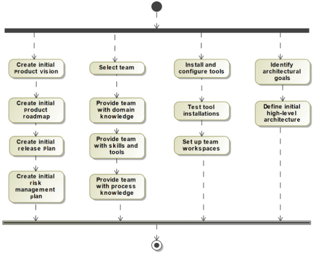
Figure 1.28: Iteration 0
Create an initial product vision
The product vision is a high-concept document about the product scope and purpose and the design approach to meet that purpose. It combines the company’s business goals with the specific needs of the customer. It identifies how this product will differentiate itself from competing products and clarifies the value to both the company and the customers.
Create an initial product roadmap
The product roadmap is a strategic plan that defines how the product will evolve over time. See the Product roadmap recipe in this chapter for more detail.
Create an initial release plan
The release plan is a tactical plan for how features will be developed in the next several product iteration cycles. The Release plan recipe discusses this in more detail.
Create an initial risk management plan
The risk management plan is a strategic plan that identifies project risks and how and when they will be addressed by allocating spikes (experiments) during the iteration cycles. See the Managing risk recipe for information on this plan.
Select the team
The team is the set of people who will collaborate on the development of the product. This includes engineers of various disciplines (systems, software, electronics, and mechanical, typically), testers, configuration managers, integrators, a product manager, and a process lead, sometimes known as a scrum master. There may be specialized roles as well as a safety czar, reliability czar, security czar, biomedical engineer, or aerospace engineer, depending on the product.
Provide the team with domain knowledge
Unless the team has prior experience in the domain, it will probably be useful to expose the team to the customer domain concepts and concerns. This will enable them to make better choices.
Provide the team with skills and tools
Any new technology, such as the use of Java or SysML, should be preceded by training and/or mentoring. The introduction of new tools, such as Jira for project tracking or Cameo Systems Modeler for SysML modeling, should likewise involve training.
Provide the team with process knowledge
The team must understand the procedures and practices to be employed on the project to ensure good collaboration. The recipes in this book identify many such practices. The project may also employ a process that incorporates a set of practices, such as the Harmony aMBSE or OOSEM processes.
See Agile Systems Engineering by Bruce Powel Douglass, at https://www.amazon.com/Agile-Systems-Engineering-Bruce-Douglass/dp/0128021209 and https://www.incose.org/incose-member-resources/working-groups/transformational/object-oriented-se-method.
Install and configure tools
The tooling environment should be set up and ready for the team to use. This might include project enactment tools such as Jira in addition to modeling tools, compilers, editors, and so on.
Test tool installations
This step verifies that the tools are properly installed and the infrastructure for the tools works. This is especially important in collaborative environments such as team clouds.
Set up team workspaces
This action refers to the physical and virtual workspaces. It is common to co-locate teams where possible and this ensures that the teams have spaces where they can do individual “thought work,” as well as collaborative spaces where they can work together.
Identify architectural goals
Architecture, as we will see in the recipe Architecture 0, is the set of large-scale product organization and design optimization decisions. Goals for architecture are often focused on simplicity, understandability, testability, stability, extensibility, robustness, composability, safety, security, and performance. Frequently these properties are in conflict; something easy to understand may not be scalable, for example. Thus, the architectural goals identify the relative importance of the goals with respect to the success of the project and the product.
Define the initial high-level architecture
This action defines the high-level architecture, congruent with the architectural goals identified in the previous step. This is known as Architecture 0, the subject of the recipe Architecture 0.
Example
For the example problem outlined in Appendix A, the road map, release plan, risk management plan, and Architecture 0 are developed in other recipes in this chapter and need not be repeated here. The other aspects are discussed here.
Create an initial product roadmap
The initial product vision and roadmap are discussed in more detail in the Product roadmap recipe.
Create the initial release plan
The release plan is discussed in more detail in the Release plan recipe.
Create the initial risk management plan
The risk management plan is discussed in more detail in the Managing risk recipe.
Select the team
In our project, we select the systems, software, electronic, and mechanical engineers for the project. The team consists of three systems engineers, two mechanical engineers, three electronics engineers, and 10 software engineers. They will all be co-located on the fourth floor of the company’s building, except for Bruce who will be working from home and come in when necessary. Each will have an individual office and there are two conference rooms allocated to the team.
Provide the team with domain knowledge
To provide the team with domain understanding, we bring in SMEs to discuss how they train themselves and others. The SMEs include professional cyclists, personal trainers, amateur cyclists, and triathletes. Members of the focus group lead the team through some workouts on existing trainers to give them an understanding of what is involved in different kinds of training sessions. Some classwork sessions are provided as well to give the team members a basic understanding of the development and enactment of training plans, including periodization of training, tempo workouts versus polarized training, and so on.
Install and configure tools
In addition to standard office tools, several engineering tools are installed and configured for the project:
- Systems engineers will use DOORS for requirements, Cameo Systems Modeler for SysML, and Groovy for simulation along with the Teamwork Cloud for configuration management.
- Mechanical engineers will use AutoCAD for their mechanical designs.
- Electronic engineers will use SystemC for discrete simulation and Allegro Cadence for their designs.
- Software engineers will use Rhapsody for UML and code generation and Cygwin for C++, along with the Rhapsody Model Manager.
- The collaboration environment will use the Jazz framework with Rational Team Concert for project planning and enactment.
Test tool installations
The IT department verifies that all the tools are properly installed, and can load, modify, and save sample work products from each. Specific interchanges between DOORS, Cameo Systems Modeler, Rhapsody, and both the Cameo Teamwork Cloud and Rhapsody Model Manager can successfully store and retrieve models.
Provide the team with skills and tools
- System engineers will receive week-long training on Cameo Systems Modeler and SysML.
- Software engineers will receive week-long training on Rhapsody and UML.
- All engineers have used DOORS before and require no additional training.
Provide the team with process knowledge
The team will use the Harmony aMBSE process and attends a 3-day workshop on the process. In addition, A Priori Systems will provide agile and modeling mentoring for the team through at least the first four iterations.
Set up team workspaces
Systems engineers are provided with a configuration computer environment that includes installed Cameo Systems Modeler, DOORS, the company’s network, and Cameo Teamwork Cloud.
Software engineers are provided with a configured computer connected to the company’s network, and can connect to the local Jazz team server to access the Jazz tooling – Rhapsody, DOORS Next Generation, Rational Team Concert, and Rhapsody Model Manager.
Define initial high-level architecture
Both of these actions are discussed in more detail in the recipe Architecture 0.
Architecture 0
Architecture is the set of strategic design optimization decisions for a system. Many different architectures can meet the same functional needs. What distinguishes them is their optimization criteria. One architecture may optimize worst-case performance, while another may optimize extensibility and scalability, and yet another may optimize safety, all while meeting the same functional needs.
The Harmony process has two primary components: the Harmony Agile Model-Based Systems Engineering process (Harmony aMBSE) and the Harmony for Embedded Software process (Harmony ESW). They each describe workflows, work products, practices, and guidance for combining agile and model-based engineering in their respective disciplines. See the author’s Real-Time Agility book for more details.
The Harmony process identifies five key views of architecture.
Subsystem and component view
This view focuses on the largest scale pieces of the system, and their organization, relations, responsibilities, and interfaces.
Concurrency and resource view
This view focuses on the concurrency units and management of resources within the system. Processes, tasks, threads, and the means for safely sharing resources across those boundaries are the primary concerns of this view.
Distribution view
This view focuses on how collaboration occurs between different computational nodes within the system and how the subsystems share information and collaboration. Communication protocols and middleware make up the bulk of this view.
Dependability view
The three pillars of dependability are freedom from harm (safety), the availability of services (reliability), and protection against attack (security).
Deployment view
Generally, subsystems are interdisciplinary affairs, consisting of some combination of software, electronic, and mechanical aspects. This view is concerned with the distribution of responsibility among the implementation of those disciplines (called facets) and the interfaces that cross engineering disciplinary boundaries.
Some recommendations for architecture in agile-developed systems are shown in Figure 1.29:
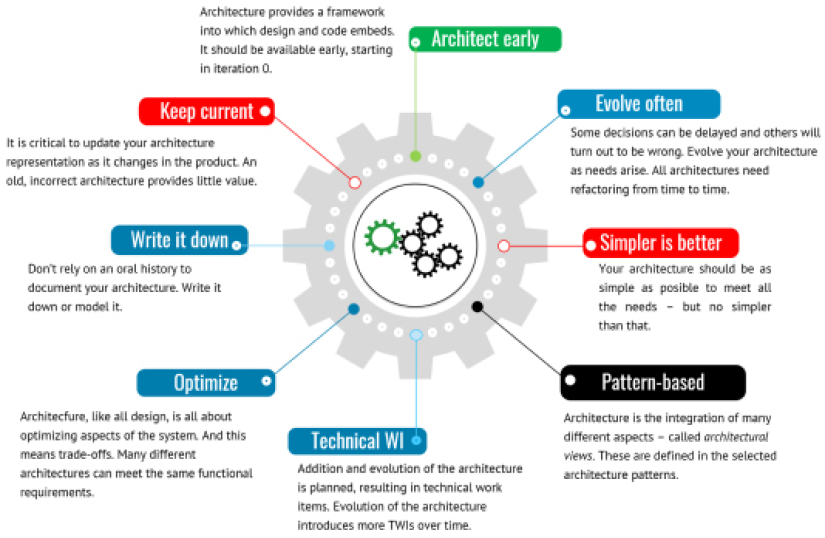
Figure 1.29: Agile architectural guidelines
Purpose
Because architecture provides, among other things, large-scale organization of design elements, as engineers develop those design elements, Architecture 0 provides a framework into which those elements fit. It is fully expected that Architecture 0 is minimalist, and therefore incomplete. It is expected that the architecture will change and evolve through the development process but it is an initial starting point.
Inputs and preconditions
A basic idea of the functionality and use of the system is necessary to develop the initial architectural concept. Thus, the preconditions for the development of Architecture 0 are the product vision and at least a high-level view of the epics, use cases, and user stories of the system.
Outputs and postconditions
The output is a set of architecture optimization criteria and an initial set of concepts from the different architectural views. This may be textual, but I strongly recommend this being in the form of a SysML architectural model. This model may have a number of different diagrams showing different aspects of the architecture. It is common, for example, to have one or more diagrams for each architectural view. In Architecture 0 many of these will be missing and will be elaborated on as the project proceeds.
How to do it
Architecture 0 is an incomplete, minimalist set of architectural concepts. Some thought is given to architectural aspects that will be given later, if only to assure ourselves that they can be integrated smoothly when they are developed. Again, it is expected that the architecture will be elaborated, expanded, and refactored as the product progresses.
Figure 1.30shows the basic workflow.
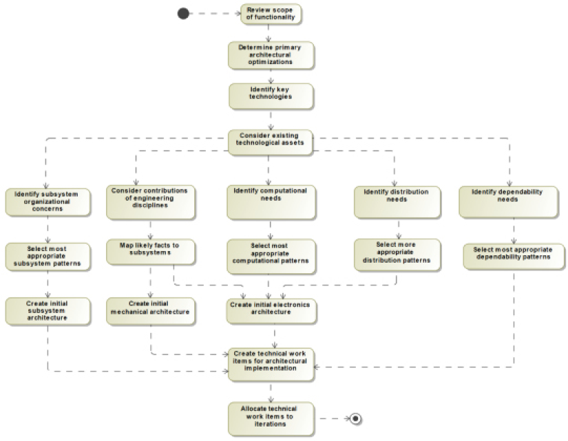
Figure 1.30: Architecture 0
Review the scope of functionality
Architectures must be fit for purpose. This means that while architectural decisions are largely about optimizations, the architecture must, first and foremost, achieve the functional needs of the system. This step reviews the essential required functionality that must be supported by the architecture.
Determine primary architectural optimizations
Selecting a design is an exercise in balancing competing optimization concerns making up the primary set of architectural goals. This step identifies and ranks the most important architectural considerations, such as worst-case performance, average performance, bandwidth, throughput, scalability, extensibility, maintainability, manufacturability, testability, and certifiability, to name a few.
Identify key technologies
It is common that one or more key technological ideas dominate the vision of the product. Electric cars, for example, have electric motors and electronic means to power them. While not necessarily defining the solutions here, it is important to at least identify the key technologies to constrain the solution space.
Consider existing technologies assets
Unless this is the very first time an organization has developed a similar product, there is likely some “prior art” that should be considered for inclusion in the new product. The benefits and costs can be considered as employing the organization’s existing technological intellectual property versus creating something entirely new.
Identify subsystem organizational concerns
Subsystems are the largest-scale pieces of the system and thus serve as the primary organization units holding elements of designs from downstream engineering. This step considers the pros and cons of different subsystem allocations and organizations. A good set of subsystems are:
- Coherent – provide a small number of services
- Internally tightly coupled – highly codependent elements should generally reside in the same subsystem
- Externally loosely coupled – subsystems should stand on their own with their responsibilities but collaborate in well-defined ways with other subsystems
- Collaborative with interfaces – interact with other subsystems in well-defined ways with a small number of interfaces
Consider contributions of engineering disciplines
The aspects of a design from a single engineering discipline is called a facet. There will typically be software facets, electronic facets, mechanical facets, hydraulic facets, pneumatic facets, and so on. The set of facets and their interactions are known as the deployment architecture, an important view of the system architecture. Early on, there may be sufficient information to engage engineers in these disciplines and consider how they are likely to contribute to the overall design.
Identify computational needs
Computational needs affect both software and electronics disciplines. If the system is an embedded system – the primary case considered in this book – then the computational hardware must be selected or developed with the particular system in mind.
These decisions can have a huge impact on performance and the ability of the software to deliver computational functionality. The software concurrency architectural concerns are not considered here, as they are solely a software concern. Nevertheless, the system must have adequate computational resources, and early estimates must be made to determine the number and type of CPUs and memory.
Identify distribution needs
Networks such as 1553 or CAN buses and other connection needs, as well as possible middleware choices including AUTOSAR, CORBA, and DDS, are the focus of this step.
Identify dependability needs
This step is crucial for safety-critical, high-reliability, or high-security systems. The initial concepts for managing dependability concerns must be considered early for such high-dependability systems and may be saved for later iterations in systems in which these are a minimal concern.
Select the most appropriate subsystem patterns
There are many organizational schemes for subsystem architecture, such as the layered pattern microkernel pattern, and channel pattern, that provide different optimizations. See the author’s book Real-Time Design Patterns for more detail on these patterns. The definition and use of patterns are discussed in more detail in Chapter 3, Developing Systems Architecture.
Map likely facets to subsystems
Facets are the contributions to an overall design from specific engineering disciplines, such as software, electronics, and mechanical engineering. We recommend that subsystem teams are interdisciplinary and contain engineers from all relevant disciplines. This step is focused on early concept deployment architecture.
Select the most appropriate computational patterns
Computational patterns concentrate on proposed computational approaches. While largely a software concern, electronics play a key role in delivering adequate computation power and resources. This is especially relevant when the computation approach is considered a key technology, as it is for autonomous learning systems or easy-to-certify cyclic executives for safety-critical systems.
Select the most appropriate distribution patterns
There are many ways to wire together distributed computing systems with networks, buses, and other communication links, along with supporting middleware. This architectural view focuses on that aspect of the system design. This impacts not just the software, but the electronic and, to a lesser degree, mechanical designs.
Select the most appropriate dependability patterns
Different patterns support different kinds of optimizations for safety, reliability, and security concerns. If these aspects are crucial, they may be added to Architecture 0 rather than leaving them for later design. Deciding to “make the product safe/reliable/secure” late in the development cycle is a recipe for project failure.
Create initial subsystem architecture
This aspect is crucial for the early design work so that the design elements have a place to be deployed. Subsystems that are not needed for early iterations can be more lightly sketched out than ones important for the early increments.
Create initial mechanical architecture
The initial mechanical architecture provides a framework for the development of physical structures, wiring harnesses, and moving mechanical parts.
Create initial electronic architecture
The initial electronics architecture provides a framework for the development of both analog electronics such as power management, motors, and actuators, as well as digital electronics, including sensors, networks, and computational resources.
Create technical work items or architectural implementation
A skeletal framework for the architecture is provided in Architecture 0 but beyond this, architectural implementation work results in technical work items that are placed in the backlog for development in upcoming iterations.
Allocate technical work items to iterations
Initial allocation of the technical work items is done to support the product roadmap and, if available, the release plan. These elements may be reallocated later as the missions of the iterations evolve.
Example
Review the scope of functionality
The Pegasus is a high-end smart cycling trainer that provides fine-grained control over bike fit, high-fidelity simulation of road feel, structured workouts, and interactions with popular online training apps. Read the content of Appendix A to review the functionality of the system.
Determine primary architectural optimizations
The primary optimization concerns in this example are determined to be:
- Recurring cost – the cost per shipped item
- Robustness – maintenance effort and cost-of-ownership should be low
- Controllability – fine-grained control of power over a broad range
- Enhance-ability – the ability to upgrade via Over-The-Air to add new sensors, capabilities, and training platforms is crucial
Identify key technologies
There are a number of key technologies crucial to the acceptance and success of the system:
- Low-energy Bluetooth (BLE) Smart for interacting with common sensors and app-hosting clients (Windows, iPad, iPhone, and Android)
- ANT+ for connecting to common sensors
- IEEE 802.11 wireless networking
- An electronic motor to provide resistance
These technologies are considered essential in this case, but we do want to take care not to overly constrain the design solution so early in the product cycle.
Consider existing technologies assets
This is a new product line for the company and so there are no relevant technological assets.
Identify subsystems organizational concerns
To improve manufacturability, we want to internalize cabling as well as minimize the number of wires. This means that we would like to co-locate the major electronics components to the greatest degree possible. However, user controls must be placed within convenient reach. Care must also be taken for adequate electric shock protection as the users are likely to expose the system to corrosive sweat.
Select the most appropriate subsystem patterns
We select the Hierarchical Control Pattern and Channel Pattern, from Real-Time Design Patterns, Addison-Wesley by Bruce Powel Douglass, 2003, as the most applicable for our systems architecture.
Create an initial subsystem architecture
Figure 1.31 shows the operational context of the Pegasus indoor training bike. This is captured in a Block Definition Diagram (BDD) in the architectural design package of the model. The operational context defines the environmental actors with which the architecture must interact during system operation:
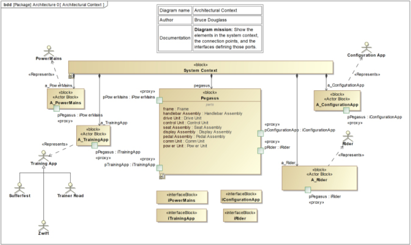
Figure 1.31: Pegasus context diagram
Figure 1.31 shows the elements in the Pegasus context. Note that we used blocks with the stereotype «Actor Block», each with a «represents» dependency to the actor they represent. This is done because in Cameo actors cannot have ports, and we wish to use ports to specify the interfaces used in the system context. These stereotypes are not defined in Cameo and so must be added in a user-created profile within the project.
Figure 1.32 shows how these elements connect in an internal block definition diagram owned by the System Context block:
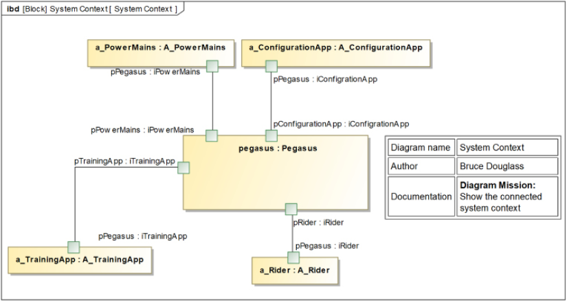
Figure 1.32: Pegasus connected context
Next, Figure 1.33 shows the set of subsystems. This diagram is like a high-level parts list and is very common in system designs in SysML:
Figure 1.33: Pegasus subsystems
Perhaps more interesting is Figure 1.34, which shows how the subsystems connect to each other in an Internal Block Diagram (IBD). This is also a commonly used architectural view in SysML models. Specifically, this figure shows the primary functional or dynamic interfaces.
I follow a convention in my architectural models in which dynamic connections – that is, ones that support runtime continuous or discrete flow – use ports, but static connections – such as when parts are bolted together – as shown using connectors with the «static» stereotype. I find this a useful visual distinction in my systems architecture diagrams. Thus, the relation between the Frame and the Drive Unit is an association but the relation between the Pedal Assembly and the Drive Unit employs a pair of ports, as there are runtime flows between the pedals and the drive motor during system operation.
Figure 1.34: Pegasus connected architecture – Primary dynamic interfaces
Consider contributions of engineering disciplines
The electronics will provide the interfaces to the user for control of the trainer as well as physical protocols for app communication. It will also provide resistance via the application of torque from the electronic motor.
The mechanical design will provide the bike frame and all the bike fit adjustments. The pedals will accept torque from the user and provide resistance to applied force via the crank arms. Additionally, the weighted flywheel smooths out resistance by providing inertial load.
Finally, the mechanical design will provide all the cable routing.
The software will provide the “smarts” and use electronics to receive and process user input from controls, inputs from connected apps, as well as from the pedals. The software will also be responsible for messages to the apps for measured sensor data.
Map likely facets to subsystems
Facets, you will remember, are the contributions engineering disciplines provide to the system design. Table 1.11 shows the initial concept for mapping the engineering facets to the subsystem architecture. This will result, eventually, in a full deployment architecture, but for now, it just highlights our current thinking about the work from the engineering disciplines that will map to the subsystems.
|
Subsystem |
Mechanical |
Electronics |
Software |
|
Frame |
Mechanical only |
||
|
Handlebar assembly |
Mechanical only |
||
|
Drive unit |
Housing for motor, flywheel, and drive train |
Motor electronics |
Discrete outputs from control unit SW controlled |
|
Control unit |
Cabling and mounting |
Primary CPU, memory, and electronic resources for SW, persistence storage for SW |
Control motor, process incoming sensor and power data, process communications with apps, and Over-The-Air updates |
|
Seat assembly |
Mechanical only |
||
|
Display assembly |
Cabling and mounting |
Display and buttons, and USB connectors (future expansion) |
User I/O management and USB interface support |
|
Pedal assembly |
Crank arms, LOOK-compatible shoe mount, connects to drive train |
Power sensor in the pedal assembly |
Discrete inputs to SW in control unit |
|
Comm unit |
Cabling and mounting |
802.11, Bluetooth (BLE) Smart, and ANT+ |
SW in control unit controls and mediates communications from sensors and external apps |
|
Power unit |
Cabling and mounting |
Converts wall power to internal power and distributes where needed |
Table 1.11: Initial deployment architecture
Identify computational needs
At a high level, the primary computational needs are to:
- Receive and process commands to vary the resistance either from the internal load, user input, or app control
- Actively control the resistance provided by the motor
- Monitor connected Bluetooth and ANT+ sensors, such as from heart-rate straps
- Send sensor data to connected apps
- Update the user display when necessary
- Perform Over-The-Air updates
Select the most appropriate computational patterns
An asymmetric dual-processor architecture is selected with a single primary CPU in the Control Unit and a secondary processor to manage communications.
Identify distrubtion needs
All communications needs will be performed by a (proposed) 16-bit communication processor housed in the comm unit; all other SW processing will be performed by the control unit on the primary CPU.
Select the most appropriate distribution patterns
To facilitate the timely distribution of information within the system, an internal serial interface, such as RS232, is deemed adequate.
Identify dependability needs
The primary safety concern is electric shock caused by faulty wiring, wear, or corrosion. Reliability needs to focus on resistance to corrosion due to sweat, and the durability of the main drive motor. Security is determined to not be a significant concern.
Select the most appropriate dependability patterns
Single-Channel Protected Pattern is selected as the most appropriate.
Create initial electronic architecture
The power interfaces are shown in Figure 1.35:
Figure 1.35: Pegasus connected architecture – Power interfaces
In addition, the drive unit hosts the primary motor to provide resistance to pedaling.
Create initial mechanical architecture
The internal mechanical connections are shown in Figure 1.36:
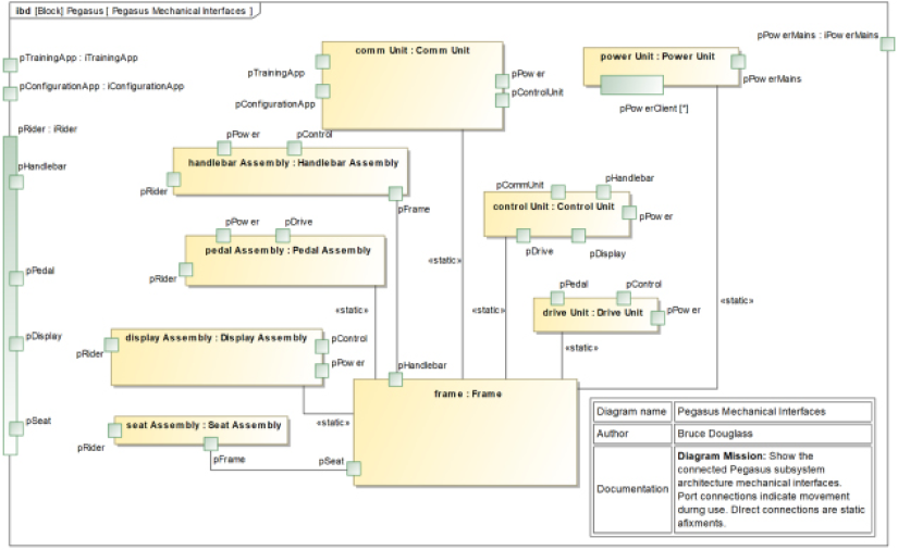
Figure 1.36: Pegasus connected architecture – Mechanical interfaces
The seat and handlebars are adjustable by the user and pedals can be added or removed, as well as providing a spot for the rider to “clip in” when they get on the bike. Thus, these connections use ports. The other connections are places where pieces are bolted together and do not vary during operation, except under catastrophic mechanical failure, so connectors represent these connections.
Create technical work items for the architectural implementation
We identify the following technical work items in Architecture 0:
Mechanical technical work items:
- CAD frame design
- Hand-built frame
- Factory built frame
Electronic technical work times:
- Motor simulation platform
- Hand-built motor
- Factory-built motor electronics
- CPU selection
- Simulated digital electronics platform
- Hand-built digital electronics platform
- Factory-built digital electronic platform
Allocate technical work items to the iterations
Allocation of such technical work items is discussed in detail in the Iteration plan recipe.
Additional note
Note that this is not a fully fleshed-out architecture. We know that in principle, for example, the pedals and the drive unit have flows between them because the pedals must provide more resistance when the main motor is producing greater resistance, but we don’t know yet if this is a mechanical power flow perhaps via a chain, an electronic flow, or discrete software messages to active resistance motors at the site of the pedals. I added a power interface to the Pedal assembly. If it turns out that it isn’t needed, it can be removed. That’s a job for later iterations to work out.
I also didn’t attempt to detail the interfaces – again, deferring that for later iterations. But I did add the ports and connectors to indicate the architectural intent.
Organizing your models
Packages are the principal mechanism for organizing models. In fact, a model is just a kind of package in the underlying SysML metamodel. Different models used for different purposes are likely to be organized in different ways. This recipe focuses on systems’ engineering models to specifically support requirements capture, use case and requirements analysis, architectural trade studies, architectural design, and the hand-off of relevant Systems Model data to the subsystem teams. In this recipe, we create not only the systems model but also the federation of models used in systems engineering. Federations, in this context, are sets of interconnected models with well-defined usage patterns defined.
Purpose
Organizing well is surprisingly important. The reasons why include:
- Grouping information to facilitate access and use
- Supporting concurrent model use by different team members performing different tasks
- Serving as the basis for configuration management
- Allowing for relevant portions of models to be effectively reused
- Supporting team collaboration on common model elements
- Allowing for the independent building, simulation, and verification of model aspects
Inputs and preconditions
The product vision and purpose are the primary input for the systems engineering model. The hand-off model is created after the architecture is stable for the iteration and is the primary input for the subsequent Shared Model and Subsystem Models.
Outputs and postconditions
The outputs are the shells of the Systems, Shared, and Subsystem Models, a federation of models for downstream engineering The Systems Model is populated with the system requirements, if they exist. The Shared Model is initially populated with (references to) the system requirements, (logical) system interfaces and (logical) data schema from the Systems Model. A separate Subsystem Model is created for each subsystem and is initially populated with a reference to its subsystem requirements from the Systems Model, and the physical interfaces and data schema from the Shared Model.
How to do it
Figure 1.37 is the workflow for creating and organizing the Systems Model. In the end you’ll have logical places for the MBSE work, and your team will be able to work more or less independently on their portions of the effort:

Figure 1.37: Organizing the systems engineering model
Review product vision, scope, and intent
Every product has a vision that includes its scope and intent. Similarly, every model you create has a scope, purpose, and level of precision. A model’s scope determines what goes into the model and what is outside of it. A common early failure of modeling happens when you don’t have a well-defined purpose for a model.
The purpose of the model is important because it determines the perspective of the model. George Box is famously attributed to the quote “All models are wrong, but some are useful.” What I believe this means is that every model is an abstraction of reality. A model fundamental represents information useful to the purpose of the model and ignores system properties that are not useful. The purpose of the model, therefore, determines what and how aspects of the product and its context will be represented.
The level of precision of the model is something often overlooked but is also important. It is too often that you will see requirements such as:
The aircraft will adjust the rudder control surface to ±30 degrees.
That’s fine as far as it goes, but what does it mean to achieve a value of +15 degrees? Are 14.5 degrees close enough? How about 14.9? 14.999? How quickly will the position of the rudder be adjusted? If it took a minute, would that be OK? Maybe 1.0 seconds? 100ms? The degree to which you care about how close is “close enough” is the precision of the model, and different needs have different levels of required precision. This is sometimes known as “model fidelity.” The bottom line is to know what you are modeling, why you are modeling it, and how close to reality you must come to achieve the desired value from your model. In this case, the model is of the requirements, their analyses, supporting analyses leading to additional requirements, and the architecture structure.
Create a new model
In whatever tool you use, create a blank, empty model.
Add the canonical system model structure
This is the key step for this recipe. The author has consulted for decades to literally hundreds of systems engineering projects, and the Subsystem Model organization shown in Figure 1.38 has emerged as a great starting point. You may well make modifications, but this structure is so common that I call it the system canonical organization.
It serves the purpose of MBSE well:

Figure 1.38: Systems model canonical structure
The main categories in Figure 1.38 are packages that will hold the modeled elements and data. The main packages are:
Model Overview Package – this package holds the model overview diagram, model summary information, and a glossary, if present.
Capabilities Package – holds all capability-related information, including requirements, use cases, and functional analyses.
Requirements Package – holds the requirements, either directly (most common) or as remote resources in the Jazz environment.
Use Case Package – holds the system use cases and use case diagrams.
Note that while this organization is labeled canonical, it is common to have minor variants on the structure.
Functional Analysis Package – holds the use case analyses, one (nested) package per use case analyzed. An example “template” package is shown with a typical structure for the analysis of a single use case.
Architecture Package – holds all design-related information for the Systems Model.
Architectural Analysis Package – hold architectural analyses, such as trade studies, usually in one nested package per analysis.
Architectural Design Package – holds the architectural design, the system and subsystem blocks, and their relations. Later in the process, it will hold the subsystem specifications, one (nested) package per subsystem.
Interfaces Package – holds the logical system and subsystem interfaces as well as the logical data schema for data and flows passed via those interfaces. Logical interfaces are discussed in more detail in Chapter 2, System Specification: Functional, Safety, and Security Analysis.
Add systems requirements, if they exist
It is not uncommon that you’re handed an initial set of system requirements. If so, they can be imported or referenced. If they are added later, this is where they go.
Modify the model structure for special needs, if required
You may identify special tasks or model information that you need to account for, so it’s OK to add additional packages as needed.
Add a model overview diagram
I like every model to contain a Model Overview Diagram. This diagram is placed in the Model Overview package and serves as a brief introduction to the model’s purpose, content, and organization. It commonly has hyperlinks to tables and diagrams of particular interest. The lower left-hand corner of Figure 1.39 has a comment with hyperlinks to important diagrams and tables located throughout the model.
This aids model understanding and navigation, especially in large and complex models:

Figure 1.39: Example model overview diagram
After systems engineering work completes and the time comes to handoff to downstream engineering, more models must be created. In this case, the input is the Systems Model and the output is the Shared Model and a set of Subsystem Models. The Shared Model contains information common to more than one subsystem – specifically the physical system and subsystem interfaces and the corresponding physical data schema used by those interfaces. The details of elaborating those models are dealt with in some detail in Chapter 4, Handoff to Downstream Engineering, but their initial construction is shown in Figure 1.40:

Figure 1.40: Organizing the shared and subsystem models
Create the Shared Model
This task creates an empty shared model. This model will hold the information shared by more than one subsystem; that is, each subsystem model will have a reference to these common interfaces and data definitions and elements.
Apply the canonical shared model structure
Apply the canonical shared model structure
The purpose of the shared model is twofold. First, using the logical interfaces and data schema as a starting point, derive the physical interfaces and data schema, a topic of Chapter 4, Handoff to Downstream Engineering. Secondly, the Shared Model serves as a common repository for information shared by multiple subsystems.
The organization shown in Figure 1.41 does that:

Figure 1.41: Shared model canonical structure
The Requirements and Interfaces packages in Figure 1.41 reference the Systems Model packages of the same name. In this way, those elements are visible to support the work in the Shared Model. The Physical Interfaces package holds the physical interfaces and data schema to be used by the subsystems. The Common Elements package holds elements used in other places in the model or in multiple subsystems. The Common Stereotypes profile holds stereotypes either used in the Physical Interfaces package or created for multiple subsystems to use.
Add a reference to the system requirements
As shown above, the Requirements package of the systems model is referenced so that they are available to view but also so that the physical interfaces and data schema can trace to them, to provide a full traceability record.
Add references to the logical interfaces and data schema
The logical interfaces and related logical data schema specify the logical properties of those elements without specifying physical implementation details. The Creating the Logical data schema recipe from Chapter 2, System Specification: Functional, Safety, and Security Analysis, goes into the creation of those elements. By referencing these elements in the Shared Model, the engineer has visibility to them but can also create trace links from the physical interfaces and data schema to them.
Add model overview diagram
As in the systems model organization, every model should have a Model Overview diagram to serve as a table of contents and introduction to the model:

Figure 1.42: Example shared model overview diagram
Create the subsystem model
Commonly, each subsystem has its own interdisciplinary team, so the creation of a Subsystem Model per subsystem provides each team with a modeling workspace for their efforts.
Apply the canonical subsystem model organization
Figure 1.43 shows the canonical organization of a Subsystem Model. Remember, that each subsystem team has their own, with the same basic organization:

Figure 1.43: Subsystem model canonical structure
The Common Stereotypes and Physical Interfaces packages are referenced from the Shared Model, while the Requirements package is referenced from the Systems Model.
We would like to think that the requirements and use cases being handed down to the subsystem team are perfect; however, we would be wrong. First, there may be additional elaboration work necessary at the subsystem level to understand those subsystem requirements. Further, discipline-specific requirements must be derived from the subsystem requirement so that the electronics, mechanical, and software engineers clearly understand what they need to do. That work is held in the Subsystem Spec Package. If we create additional, more detailed use cases, they will be analyzed in the Functional Analysis Package in the same way that the system use cases are analyzed in the Systems Model.
The Deployment Architecture Package is where the identification of the facets and the allocation of responsibilities to the engineering disciplines takes place. To be clear, this package does not detail the internal structure of the facets; the electronics architecture, for example, is not depicted in this package, but the electronics facet as a black box entity is. Further, the interfaces between the electronics, software, and mechanical facets are detailed here as well.
Lastly, the SW Design Package is where the design and implementation of the software will be done. It is expected that the software will continue to work in the model but that the other facets will not. Alternatively, the software engineers can create their own separate model that references the subsystem model. For electronics and mechanical design, we expect that they will use their own separate tools and this model will serve only as a specification of what needs to be done in those facets. It is possible that the electronics design could be done here, using SysML or UML and then generating SystemC, for example, but that is fairly rare. SysML and UML are poorly suited to capture mechanical designs, as they don’t have any underlying metamodel for representing or visualizing geometry.
Copy the subsystem specification
The Subsystem Package is copied (rather than referenced) from the Systems Model. This model holds the subsystem details such as subsystem functions and use cases. Of course, the name of this package in Figure 1.43 is misleading; if the name of the subsystem was Avionics Subsystem, then the name of this package would be Avionics Subsystem Package or something similar.
In a practical sense, I prefer to copy the subsystem package from the Systems Model, because that isolates the Subsystem Model from subsequent changes to that package in the Systems Model that may take place in later iterations. The subsystem team may then explicitly re-import that changed Subsystem Model at times of its own choosing. If the subsystem package is added by reference, then whenever the systems team modifies it, the changes are reflected in the referencing Subsystem Model. This can also be handled by other means, such as referencing versions of the system model in the configuration management set, but I find this conceptually easier. However, if you prefer to have a reference rather than a copy, that’s an acceptable variation point in the recipe.
Add a reference to the subsystem requirements
The Requirements package in the Systems Model also holds the derived subsystem requirements (see Chapter 2, System Specification: Functional, Safety, and Security Analysis). Thus, referencing the Requirements package from the system model allows easy access to those requirements.
Add a reference to the physical interfaces and data schema
Logical interfaces serve the needs of systems engineering well, for the most part. However, since the subsystem team is developing the physical subsystem, they need to know the actual bit-level details of how to communicate with the actors and other subsystems, so they must reference the physical interfaces from the Shared Model.
Add model overview diagram
As before, each model should have a Model Overview diagram to serve as a table of contents and introduction to the model.
How it works
At the highest level, there is a federated set of models defined here. The Systems Model holds the engineering data for the entire set, and this information is almost exclusively at the logical level of abstraction. This means that the important logical properties of the data are represented – such as the extent and precision of the data – but their physical properties are not. Thus, we might represent an element such as a Radar Track in the Systems Model as having a value property of range with an extent of 10 meters to 300 kilometers and a precision of ± 2 meters. Those are logical properties. But the physical schema might represent the value as a scaled integer with 100* the value for transmission over the 1553 avionics bus. Thus, a range of 123 kilometers would be transmitted as an integer value of 12,300. This representation is a part of the physical data schema that realizes the logical properties.
Beyond the Systems Model, the Shared Model provides a common repository for information shared by multiple subsystems. During the systems engineering work, this is limited to the physical interfaces and associated physical data schema. Later in downstream engineering, other shared subsystem design elements might be shared, but that is beyond our scope of concern.
Lastly, each subsystem has its own Subsystem Model. This is a model used by the interdisciplinary subsystem team. For all team members, this model serves as a specification of the system and the related engineering facets. Remember that a facet is defined to be the contribution to a design specific to a single engineering discipline, such as software, electronics, or mechanical design. Software work is expected to continue in the model but the other disciplines will likely design their own specific tools.
Example
Figure 1.44 shows the initial organization of the Pegasus System Model, with Architecture 0 already added (see recipe Architecture 0). I’ve filled in a few other details, such as adding references to diagrams to illustrate how they might be shown here:

Figure 1.44: Pegasus system model – overview diagram
The shared model and subsystem model are not created early in the MBSE process but rather late, after the Pegasus architecture work is completed for the current iteration and the work developing the hand-off to downstream engineering is underway. We will discuss their creation in Chapter 4, Handoff to Downstream Engineering.
Managing change
In real engineering environments, work products are not the result of a single person working in isolation. Rather, they represent the integration of the efforts of many people. In model-based systems engineering, the model is central to the project and this means that many people must work simultaneously on the model. Without getting in each other’s way. Or losing work.
The heart of managing such a shared engineering work product is change management and its close cousin configuration management. The former is the process and procedures that govern how changes made to a work product are controlled, including the controlled identification of changes, the implementation of those changes, and the verification of the changes. Configuration management is a systems engineering process for establishing and maintaining consistency of a product’s performance, functional, and physical attributes with its requirements, design, and operational information throughout its life.
See https://en.wikipedia.org/wiki/Configuration_management for more information. Both of these are deep and broad topics and will be treated somewhat superficially here. It is nevertheless an important topic, so we will present a simple workflow for change and configuration management of models in this recipe.
Central to this recipe is the notion that we change a model for a purpose. In traditional engineering processes, this is managed via a change request, sometimes called an Engineering Change Order (ECO). In agile processes, this is due to a work item in the iteration backlog. In either case, the change is made to the model for a reason and to achieve some goal. The problem is that many people need to change other elements in the model to achieve other goals. Frequently, different changes must be made by different people to the same model elements.
The concept of a package was introduced early in the development of UML. A package is a model element that contains other model elements, including use cases, classes, signals, behaviors, diagrams, and so on. As such, it is the fundamental unit of organization for models. It was also intended to be the fundamental Configuration Item (CI), the atomic piece for configuration management. It was envisioned that a modeler would manage the configuration of a package as a unit, including all its internal contained elements together. Modern tools like Cameo and Rhapsody support this but also allow finer-grained configuration management down to the individual element level, if desired. Nevertheless, the package remains the most common CI.
The terms version and revision are common terms in the industry around this topic. A model version is a changed model. Such changes are typically considered minor. A revision is a controlled version and is generally considered a major change. It is common that revisions are numbered as whole numbers and versions are fractional numbers. Version 19.2 indicates revision 19 version 2. Revisions are considered baselines and permanent, and versions are minor changes and temporary. Revisions generally go through a more robust verification and validation process, often at the end of a sprint. Versions may be created at each test-driven development cycle (known in the Harmony process as the nanocycle – see the Test-Driven Modeling pattern in Chapter 5, Demonstration of Meeting Needs) and so come and go rapidly.
All this is relevant to the two basic workflows for change and configuration management: Lock and Release and Branch and Merge. Both primarily work at the package level.
Purpose
The purpose of this recipe is to provide a workflow for robust change control over model contents in the presence of multiple and possibly simultaneous changes to the model made by different engineers.
Inputs and preconditions
This recipe starts after a model is baselined. A baseline means that the model is stored under a configuration and change control environment, usually after it has achieved some basic level of maturity. This means that there is a current source of truth for the model contents, and all changes are managed by the configuration and change control environment. The second precondition is the presence of a change to be made to the model. This recipe does not concern itself with how the decision is made to proceed with the change, only that the decision has been made.
Outputs and postconditions
The output is the updated model put back under configuration and change control either as a version or as a revision, depending on the scope of the change.
How to do it
Figure 1.45 shows the workflow for this recipe. Two alternative flows are shown. On the left is the more common and simpler Lock and Release sub-workflow, and on the right is the Branch and Merge sub-workflow. Both sub-workflows reference the Make Change activity, which is shown as a nested diagram on the right of the figure:
Figure 1.45: Managing change
Get work item
The start of the workflow is to get a request to modify the baseline model. This can be the addition of a model structure, behavior, functionality, or some other property. It can also be to repair an identified defect or pay off some technical debt.
Determine the change to be made
Once the request for change has been received, the engineer generally develops a plan for the modification to be made. The work may involve a single element, an isolated set of elements in the same package, or broad, sweep changes across the model.
Lock and release
The Lock and Release workflow is by far the most common approach to modifying a model under configuration control. The detailed sub-tasks follow. Its use means that other engineers are prohibited from making changes to the elements checked out to the first engineer, until the locks owned by the latter are released.
Open the model
This step opens the model in the configuration management repository.
Make a change
This makes and verifies the change in the model. It has a number of sub-tasks, which will be described shortly.
Branch and merge
This alternative sub-workflow is useful when there are many people working on the model simultaneously. People will create a separate branch in which to work so that they will not interfere with anyone else’s work. The downside is that it is possible that they will make incompatible changes, making the merge back into the main trunk more difficult. This sub-workflow has three steps.
Create a branch
In this step, the engineer creates a branch of the main project; this latter model is known as the trunk. A branch is a separate copy of the project completely independent of the original, but containing, at least at the start, exactly the same elements.
Merge a branch
This step takes the changes model and merges those changes back into the main project or trunk. There are usually changes that are merely additions but other changes may be in conflict with the current version of the trunk, so this step may require thoughtful intervention.
Make a change activity
This activity is referenced in both the Lock and Release and Branch and Merge sub-workflows. It contains several included steps.
Lock relevant elements
Whenever you load a model that is under configuration control, you must explicitly lock the elements you wish to modify.
Modify elements
This step is where the actual changes to the model are performed.
Verify change
Before checking in a changed model, it is highly recommended that you verify the correctness of the changes. This is often done by performing tests and a review/inspection of the model elements. Recipes in Chapter 5, Demonstration of Meeting Needs, discuss how to perform such verification.
Unlock relevant elements
Once the changes are ready to be put back into the configuration management repository, they must be unlocked so that other engineers can access them.
Store updated model
In this final step of the Make Change Activity, store the unlocked model back into the configuration management repository.
Example
Since we are using Cameo in this book, we will be using Cameo Teamwork Cloud as the configuration management environment. Other tools, such as Rhapsody from IBM, can use various configuration management tools but with Cameo, either Teamwork Cloud or the older Teamwork Server is required.
Because the more common Lock and Release workflow is a degenerative case of the more elaborate Branch and Merge sub-workflow, we will just give an example of the latter.
The example here shows a context for an exercise bike. The context block is named Pain Cave, and it contains a Rider part that represents the system user, and an Exercise Bike part that represents the system under design. The Rider block provides cadence and power as inputs to the system as flow properties and receives resistance back:
Figure 1.46: Pain cave model composition architecture
Figure 1.47 shows the internal block diagram connecting the Rider and Exercise Bike parts in the context of the Pain Cave, while Figure 1.48 shows the internal structure of the Exercise Bike itself:
Figure 1.47: Pain cave connected context
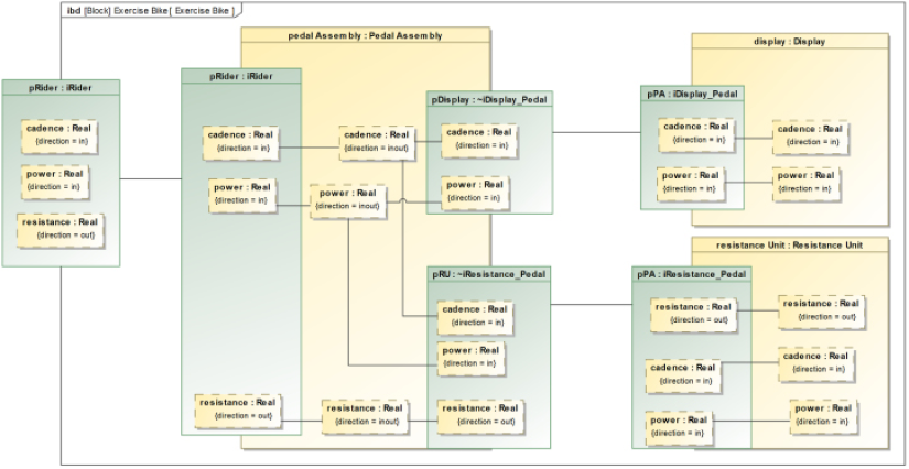
Figure 1.48: Exercise bike connected architecture
Finally, Figure 1-49 shows the behaviors of two elements, Rider and Resistance Unit. The concept here is that the Resistance Unit produces resistance based on the power and cadence it receives from the Rider. Of course, this behavior performed is not in any way realistic but just a simple example of behavior:
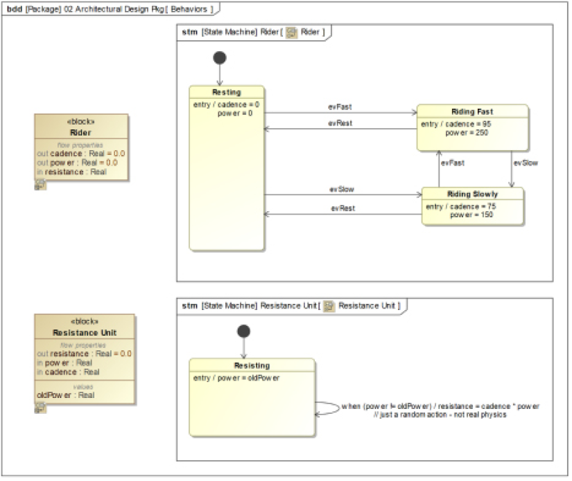
Figure 1.49: Behaviors
This system does execute, as can be seen in Figure 1.50, which shows the current states of the running simulation using Cameo’s Simulation Toolkit, and the current values of the flow properties in Figure 1.51. In Cameo, you can visualize a running system in a number of ways, including the creation of diagrams that contain other diagrams; for activity and state diagrams, Cameo highlights the current state or action as it executes the model. The Simulation Toolkit also exposes the current instances and values held in value properties during the simulation:
Figure 1.50: Pain cave simulation view
Figure 1.51: Pain cave values during simulation
Get work item
For this example, we will work on two user story work items together:
- As a rider, I want to be able to see the pedal cadence and power as I ride so that I can set my workout levels appropriately.
- As a Rider, I want to be able to control the amount of resistance, given cadence, and power so I have finer control over my workout efforts.
Determine the change to be made
In this simple example, the changes are pretty clear. The Display block must be able to get input from the Rider to change the scaling factor for the resistance, and then send this information to the Resistance Unit. The Resistance Unit must incorporate the scaling factor in its output. Additionally, behavior must be added to the Display block to display cadence and power.
Create branch
In the Cameo tool, after logging in to the Teamwork Cloud environment, select your project using Collaborate > Projects menu to select your project. At the right of the project from which you want to create a baseline, click on the ellipsis to open the Select Branch dialog, then select Edit Branches, which opens the Edit Branches dialog. Here, select the version from which you wish to branch and select Create Branch. These dialogs are all shown in Figure 1.52:
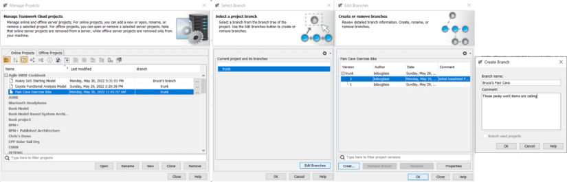
Figure 1.52 Creating a branch
Once created, you can open the branch in the Manage Projects dialog.
Make Change::Lock relevant elements
To edit the elements you must lock them. In Cameo, this is a right-click menu option for elements in the containment tree. We will work exclusively in the 02 Architectural Design Pkg package, so we will lock that package and all its contents. In Cameo, you must select Lock Elements for Edit Recursively to lock the package and the elements it contains. If you lock without recursion, you only have edit rights to the package itself and not its content.
Make Change::Modify elements
Let’s look at the changes made for each of the work items:
- As a rider, I want to be able to see the pedal cadence and power as I ride so that I can set my workout levels appropriately.
For this change, we’ll modify the Display block to have a state behavior driven by a change event, whose specification is when either the power or the cadence changes. This requires the addition of a couple of value properties. The Display state machine is shown in Figure 1.53. For our purposes here, we’ll just use Groovy print statements to print out the values. In the simulation, these print statements output text to the console of the Simulation Toolkit:
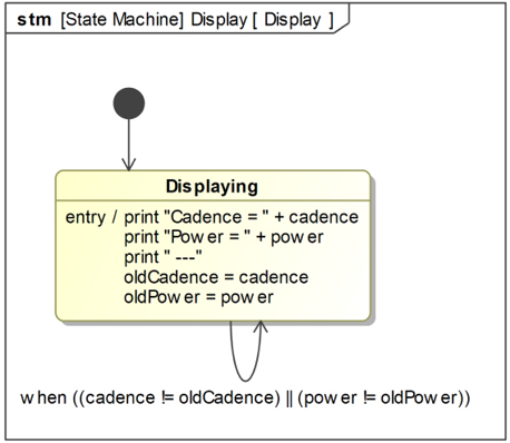
Figure 1.53: Display state machine
- As a Rider, I want to be able to control the amount of resistance, given cadence, and power.
For this work item, we’ll need to add a pair of ports between the Rider and the Resistance Unit blocks so the Rider can send the evAugmentGear and evDecrementGear events. The Rider state machine will be extended to be able to send these events (under the command of the simulation user), and the Resistance Unit state machine will accept these events and use them to update the scaling factor used to compute resistance. We will also need to add said scaling factor and update the computation.
Figure 1.54 shows the updated Rider state machine and Figure 1.55 shows the updated Resistance Unit state machine. The latter state machine was refactored a bit to account for the issue that you also want to recompute the resistance when the gearing is changed, as well as when cadence or power changes:
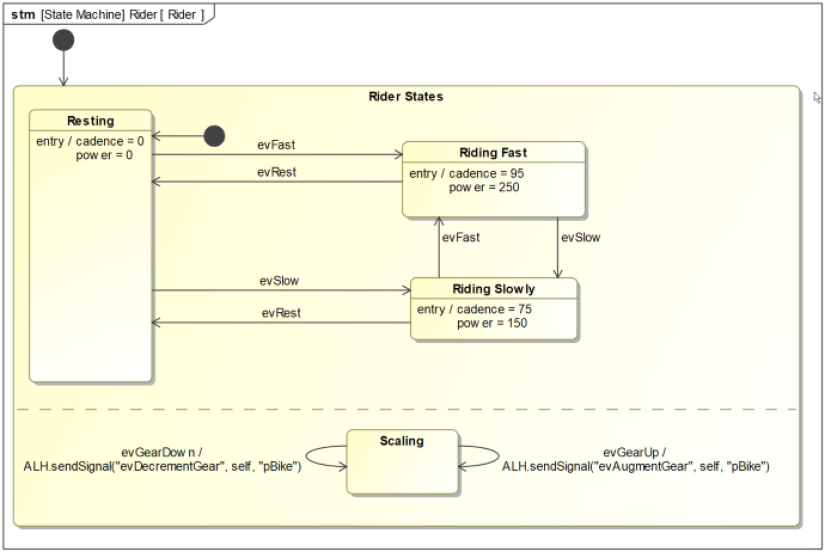
Figure 1.54: Updated rider state machine
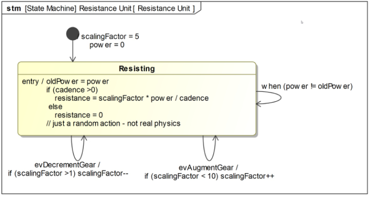
Figure 1.55: Updated resistance unit state machine
The updated block definition diagram is shown in Figure 1.56. Note the changes to the interface block iRider, the addition of a new port, and the value property for the Resistance Unit:
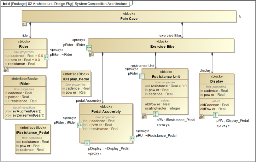
Figure 1.56: Updated pain cave BDD
Lastly, Figure 1.57 shows the updated internal block diagram for the Exercise Bike. Note that the Exercise Bike.pRider port is now also connected to the pRider port of the Resistance Unit. This allows the latter to receive the gearing events:
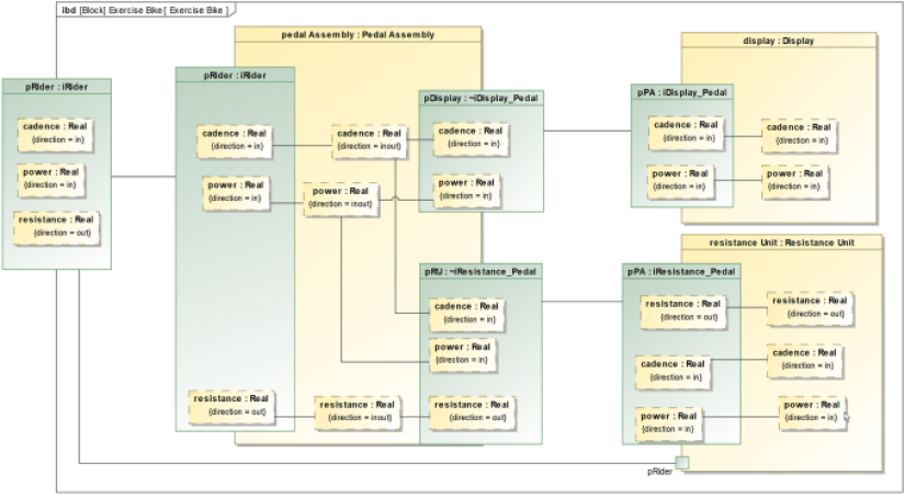
Figure 1.57: Updated exercise bike IBD
Make Change::Verify change
To make sure we made the changes correctly, we can run the simulation. As a simulation operator, you can use the simulation toolkit to start the operation sending the evFast signal to the Rider, and then send the evGearUp and evGearDown events to see the effect on the resulting resistance. Also, you can check the output console to ensure the cadence and power are being displayed.
Cameo makes it simple to create a simulation view that allows visualization of the behaviors (see Figure 1.58). I’ve superimposed the console window in the figure so you can see the results of the Display block behavior:
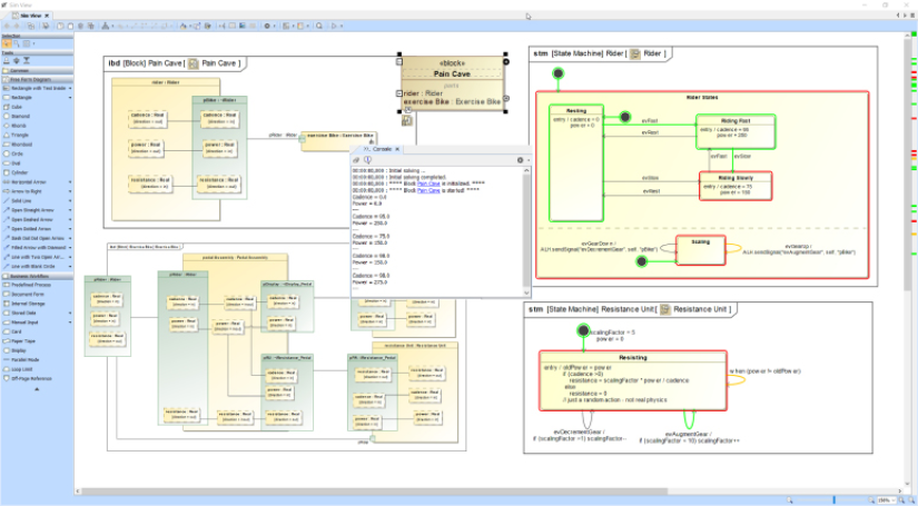
Figure 1.58: Exercise bike verification via simulation
Make Change::Unlock relevant element
Having made and verified the changes, we can save the changes. Right-click the package in the containment tree, and select Lock > Unlock elements recursively. This will open the Commit Project to Server dialog.
Make Change::Store the updated model
In the Cameo tool, unlocking the elements also stores them in the Teamwork Cloud repository, so this step is done.
Merge a branch
We now have a baselined and unmodified trunk version and our updated branch version. The last step is to merge our branch changes into the baseline.
In Cameo, open the trunk (target) model, then select Collaborate > Merge From; this opens the Select Server Project dialog. Here, select the branch version you just created:
Figure 1.59: Selecting the branch for merge
Then a dialog pops up if you want to merge with the trunk locked or not. Always merge with the trunk locked.
Once you click on Continue, the Merge dialog opens. There are many options for seeing what the changes are, accepting some changes, and rejecting others. Color coding identifies the different kinds of changes: addition, deletions, and modifications:
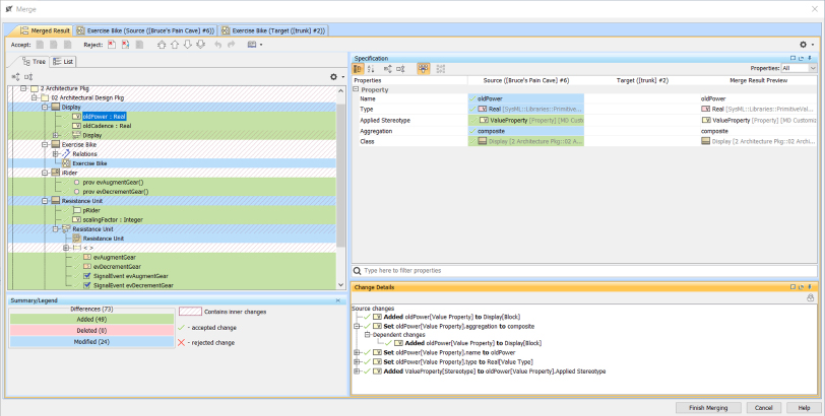
Figure 1.60: Review merge changes
Any conflicting changes are highlighted and can be resolved manually, by right-clicking and accepting either the source (updated branch) change or keeping the target (trunk) version of the element. Cameo has a nice feature that allows you to explore diagrammatic changes graphically. The scroll bar at the bottom of the window allows you to switch between the unchanged and changed views of the diagram.
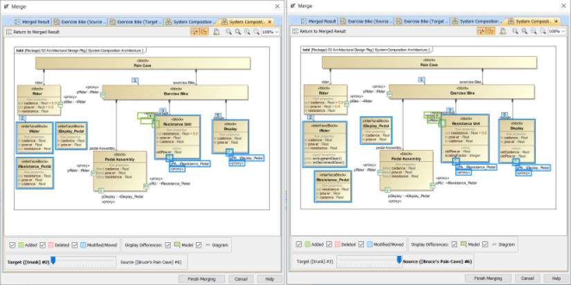
Figure 1.61: Reviewing diagrammatic changes
Click Finish Merging when you’re ready to complete the merge process and click Collaborate > Commit Changes to save the updated merged model to the trunk. Remember that the Branch and Merge approach is the lesser-used workflow, and the simpler Lock and Release approach is more common. Just remember to lock and unlock elements recursively and be sure to unlock when you’re done making your changes.
Join our community on Discord
Join our community’s Discord space for discussions with the author and other readers: