


 Download code from GitHub
Opening, Inspecting, and Repairing CAD and Mesh files
Welcome to this book, 3D Printing with Fusion 360. Fusion 360 is a great tool to create and edit designs using parametric or direct modeling methods. With the addition of automated modeling, generative design, and topology optimization technologies, Fusion 360 users now have a plethora of methods to design for additive manufacturing. This book will provide the necessary steps for you to manufacture your designs with Fusion 360, using common 3D-printing technologies such as fused filament fabrication, stereolithography, selective laser sintering, binder jetting, and metal powder bed fusion. You will also get valuable tips and tricks on how to set up Fusion 360, which will allow you to get the most out of the software for your 3D-printing needs.
Fusion 360 is a cloud-based 3D modeling, Computer Aided Design (CAD), Computer Aided Manufacturing (CAM), computer aided engineering (CAE), and Printed Circuit Board (PCB) design software platform for professional product design and manufacturing (https://www.autodesk.com/products/fusion-360/overview).
It is available for both Windows and macOS, with simplified applications available for both Android and iOS. Fusion 360’s initial release dates back to 2013, which is around the same time that 3D printing became mainstream. During the 2010s, the maker community quickly adopted Fusion 360 for designing and manufacturing.
When manufacturing designs using 3D printing, mesh (STL) files were the only file types that early 3D printing slicer software would accept as input. As the maker community created and shared their designs publicly using STL files on web pages such as thingiverse.com, the number of 3D printable designs increased exponentially. Unfortunately, the STL file format has many problems and limitations. To fix those problems, the 3D printing community needed reliable and easy-to-use software.
Fusion 360 always included functionality around working with both CAD and mesh files, making it a great tool for 3D printing. However, Fusion 360’s mesh functionality was offered as a technology preview and needed to be turned on within Fusion 360’s preferences. Autodesk – the parent company of Fusion 360 – releases new updates for Fusion 360 regularly. With the July 2021 update of Fusion 360, Autodesk made significant changes to the mesh workflows, by graduating the mesh workspace from being a part of a tech preview to being a part of Fusion 360’s Design workspace.
Today, you can use Fusion 360 to open, inspect, and repair mesh files that you can download from numerous third-party sources.
In this chapter, we will start by looking at the various ways we can bring CAD/mesh data into Fusion 360 by introducing you to Fusion Team and the Fusion 360 user interface. We will go over how to create projects and folders to better organize our data. Next, we will show numerous methods to insert mesh files such as STL, OBJ, and 3MF into Fusion 360. We will end the chapter by inspecting the mesh data we insert into Fusion 360 for potential defects and repairing those defects automatically and manually.
In this chapter, we will cover the following topics:
- Opening and uploading workflows for CAD models and mesh files
- Inserting Mesh workflows for STL, OBJ, and 3MF files
- Inspecting Mesh bodies and repairing them
By the end of this chapter, you will have learned how to open models created using other tools in Fusion 360. You will have learned how to insert mesh files into Fusion 360. You will also know how to inspect and repair mesh files using automatic and manual methods.
Technical requirements
Most of the topics covered in this book apply to all licensing levels (personal/hobby, start-up, educational, and commercial) of Fusion 360. However, the book will also cover advanced functionality not available to personal/hobby use licenses. Such advanced functionality will be identified as N/A for Personal Use, and Requires Access to Extension as appropriate.
Fusion 360 has the following system-specific requirements:
- Apple® macOS:
- macOS 13 Ventura – version 2.0.15289 or newer
- macOS 12 Monterey
- macOS 11 Big Sur
- Microsoft Windows:
- Windows 11
- Windows 10 (64-bit) – version 1809 or newer
- CPU, memory, and disk space requirements:
- x86-based 64-bit processor (for example, Intel Core i and AMD Ryzen series), 4 cores, and 1.7 GHz or greater; 32-bit is not supported. Apple silicon processors require Rosetta 2.
- 4 GB of RAM and 8.5 GB of storage.
Important note
A detailed list of system requirements can be found here: https://knowledge.autodesk.com/support/fusion-360/learn-explore/caas/sfdcarticles/sfdcarticles/System-requirements-for-Autodesk-Fusion-360.html.
The lesson files for this chapter can be found here: https://github.com/PacktPublishing/3D-Printing-with-Fusion-360.
Opening and Uploading workflows for CAD models and Mesh files
Fusion 360 is a cloud-connected CAD/CAM/CAE and PCB design tool. You can create new designs or open designs created in other tools that are saved as CAD or mesh files. In this section, we will cover all the ways you can open models created by other software in Fusion 360 so that we can start getting them ready for 3D printing.
As Fusion 360 is cloud-connected software, it has cloud storage and data-sharing capabilities built in. As a Fusion 360 user, you automatically get access to a cloud-connected data storage and management tool called Fusion Team. This tool also allows you to administer your team of Fusion users by giving you tools for permissions, version control, markup, and comments. According to an Autodesk Knowledge Network article, Fusion 360 users automatically get unlimited storage for Fusion 360 data and 500 GB of data storage for non-Fusion documents. That is a generous amount of storage to tackle any project.
Important note
For more information on how cloud data storage works, you can refer to this article at https://knowledge.autodesk.com/support/fusion-360/learn-explore/caas/sfdcarticles/sfdcarticles/How-big-is-the-cloud-storage-for-Fusion.html.
After creating an Autodesk account and gaining access to Fusion 360, regardless of your licensing level, you can log in to your Fusion Team account (https://myhub.autodesk360.com/) and start your Fusion 360 data management journey.
If you are an individual user, you don’t have to worry about changing teams. However, if you work for an organization with multiple Fusion 360 users, your organization may have multiple teams already set up. For example, each user may have their own team. You can switch the active team by selecting the profile icon in the top-right corner of the screen, as shown in the following screenshot:
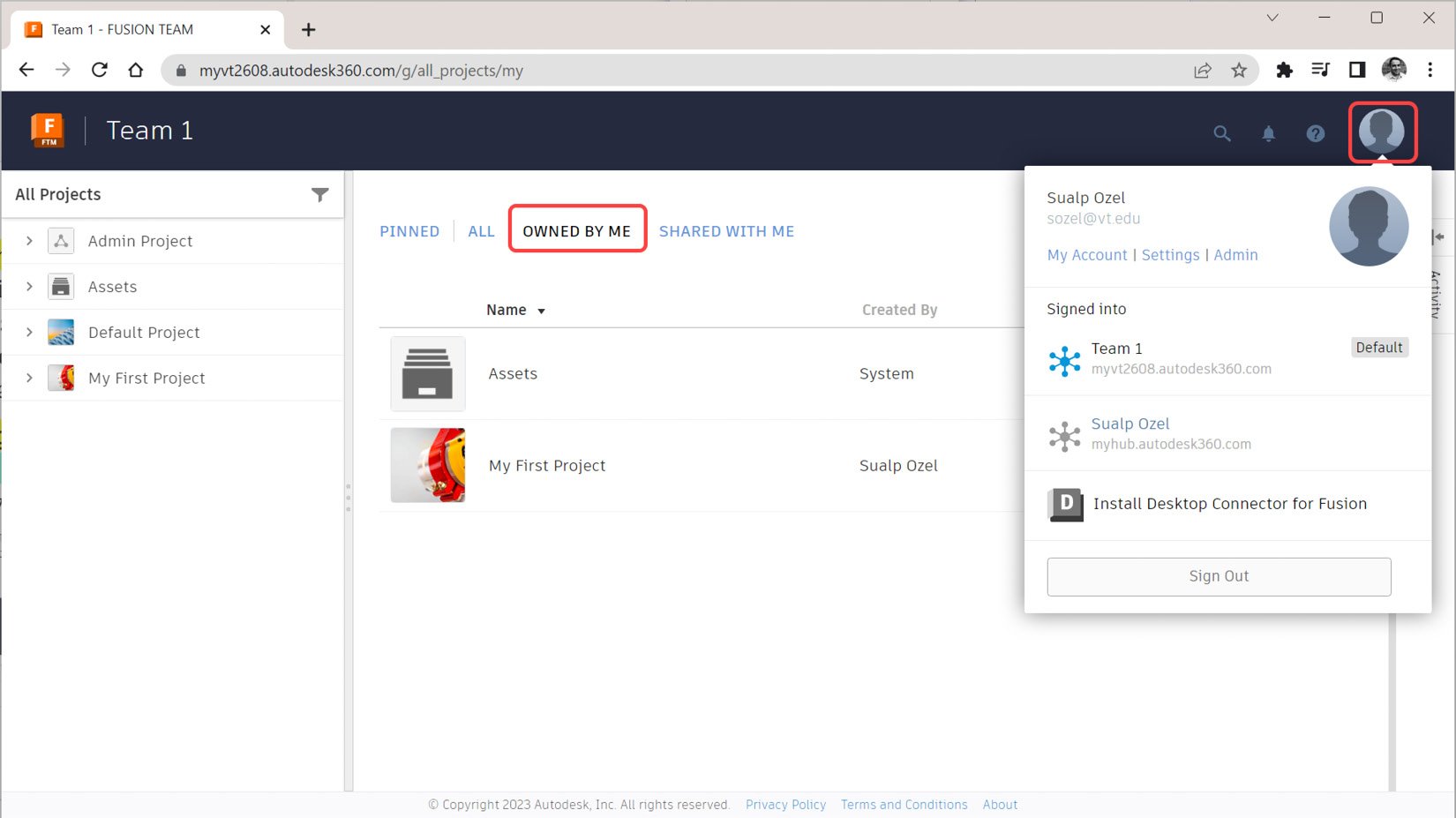
Figure 1.1 – My FUSION TEAM view with an OWNED BY ME filter applied
Figure 1.1 shows my Fusion TEAM view on a Google Chrome browser with the OWNED BY ME filter applied to the list of projects. If I were part of an organization with multiple teams, I would select the Profile icon in the top-right corner and change my active team to participate in a project stored in another team’s hub. Figure 1.1 also shows that, by default, we have two items that are owned by me – Assets and My First Project.
In Figure 1.2, you can see that by selecting My First Project and expanding Project Details, we can edit the project name and image and manage members who can contribute to and view the contents of this project:
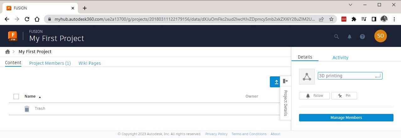
Figure 1.2 – You can rename projects on the Project Details screen
Once the project has a name we approve (in Figure 1.2, I renamed the project 3D printing), we can take a look at various methods we have available to upload designs and other documents to Fusion Team and Fusion 360.
The first option we have to upload our designs and documents to Fusion Team is within the created project itself. As shown in Figure 1.3, we are in a project named 3D printing, and we can select the blue Upload button to see the various options we have to upload things, such as File, Folder, Assembly, and From Dropbox. If we select File from that dropdown, we can upload any file stored on our local storage directly to our active project on Fusion TEAM. If the files we upload contain mesh or CAD geometry (for example, STL, STEP, SAT, Inventor, or Solidworks), we will be able to open those designs in Fusion 360 for further editing and manufacturing. If they are non-CAD files (for example, Microsoft Word documents or PDF files), we won’t have native access to them in Fusion 360, but we can still view them in our internet browser or mobile apps.
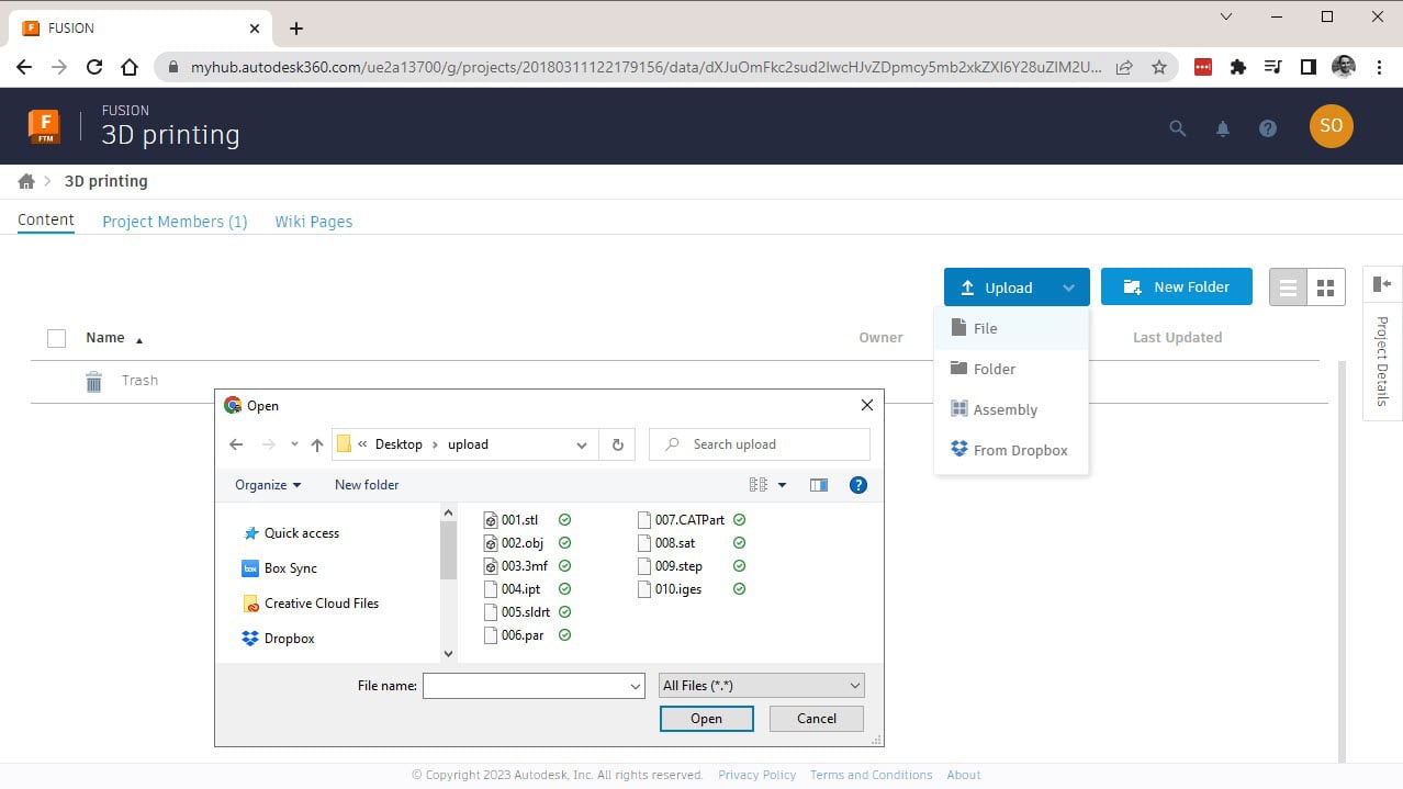
Figure 1.3 – Uploading local files to our 3D printing project on Fusion TEAM
If you are used to traditional desktop CAD software, uploading files to a Fusion project using FUSION TEAM may not have the intuitive workflow you are familiar with. However, it is a useful way to quickly upload multiple files associated with a project to your Autodesk cloud storage.
If you seek a more traditional workflow to open your CAD or mesh files, you will want to have Fusion 360 installed on your computer. You can download and install Fusion 360 from the following link: https://www.autodesk.com/content/autodesk/global/en/products/fusion-360/trial-intake.
Once Fusion 360 is installed and started, you can access the File dropdown and select Open. When you do, you will be greeted with the Open dialog. As shown in Figure 1.4, select the Open from my computer… option within this dialog, and you will be able to select from a list of supported mesh and CAD file types, as shown in Figure 1.5:
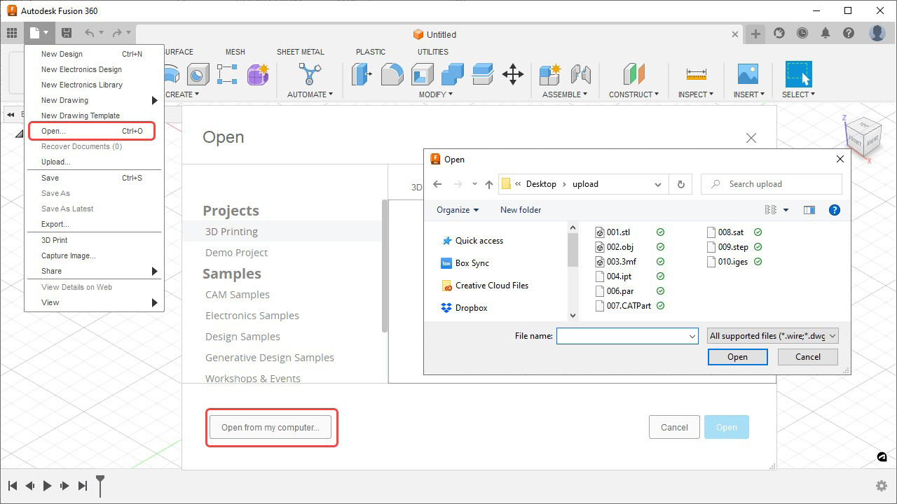
Figure 1.4 – The File | Open... workflow allows you to open CAD and mesh files from your computer
In this dialog, you will have the option to open any of the Mesh or CAD file types that Fusion 360 supports. As Autodesk regularly updates Fusion 360, you never have to worry about not having access to the latest CAD translators:
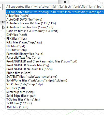
Figure 1.5 – A list of the available CAD and MESH file types that Fusion 360 can open
This is a great option to open a single file quickly, but there are several downsides to this option:
- You can only open one file at a time using this method.
- When using this method, you end up in Direct Modeling mode upon opening a CAD file. If you want to capture design history, you will need to manually turn on the design history using the browser. Modeling with the Design history and Direct modeling methods will be covered in detail in Chapter 2.
- You do not get a chance to set the units or part placement when opening STL/OBJ files.
In conclusion, if you try to open STL or OBJ files, this is not the option I would recommend. However, if you open a CAD file (for example, STEP or SAT) or a 3MF file, this is a quick and easy option that you may want to use. Don’t forget to manually turn on Capture Design History if you want to store your edits in the timeline, as shown in Figure 1.6:
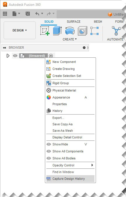
Figure 1.6 - After a File | Open... workflow, turn on Capture Design History via the browser
Another option available when opening CAD and Mesh files is within Fusion 360’s Data Panel. You can access the Data Panel window by selecting the Show Data Panel icon, located in the top-left corner of the interface, as shown in Figure 1.7.

Figure 1.7 - Show/Hide Data Panel
Once the data panel is visible, you can navigate to the team and project where you wish to upload your design data. Once in the appropriate project, you can create new folders to organize your designs and documents further. Once you are in the desired project/folder location, you can use the Upload button, as shown in Figure 1.8, and select or drag and drop files to the upload dialog that is on your screen. Either option will allow you to upload multiple CAD or mesh files to the designated team/project/ folder location. Please note that each uploaded file will become its own Fusion design document.
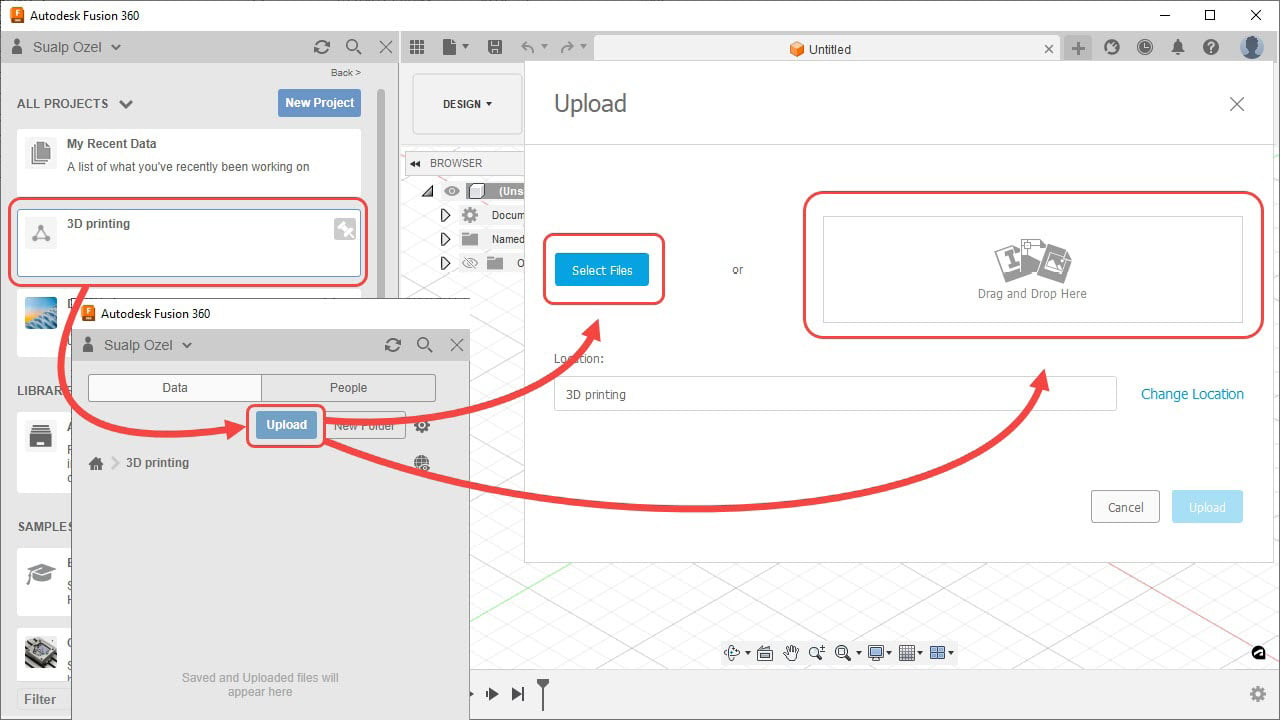
Figure 1.8 – Uploading multiple Mesh and CAD documents to Fusion 360 using the Data Panel
This is a great option to upload multiple CAD models to Fusion 360. However, just like the previous option, you will have to turn on Capture Design History if you want to store your edits in the timeline, as shown in Figure 1.6. And just like the previous option, this method is not one I would recommend opening STL or OBJ files, as it does not give you initial control over units of part placement during the import process.
Another lesser known but rather useful option is based on the Fusion 360 mobile app. If you have a mobile device, you can download the Fusion 360 app from the relevant app store, and you can browse for and upload CAD or Mesh files stored on your phone or tablet, as shown in Figure 1.9:
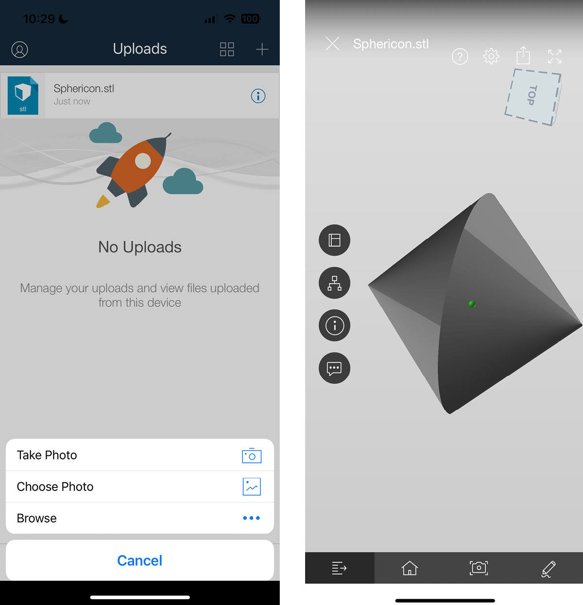
Figure 1.9 – A view on a mobile device after uploading an STL file to Fusion Team
This method is particularly useful if you do not have your computer available when you receive a CAD or mesh file. In such instances, you can quickly upload the design to your Fusion Team/project/folder so that you and your team members can start working on the design right away. Just like the previous methods, this method also requires that you manually turn on the Capture Design History within Fusion 360’s browser if you want to store your edits in the timeline, as shown in Figure 1.6.
Important note
If you upload an STL/OBJ file to Fusion Team or the Fusion 360 app, after opening it in Fusion 360, you will have to inspect the units and the position of the mesh body to make sure it matches the original design intent. Fusion uses centimeters as the default unit system when creating Fusion 360 design documents from mesh file types with no units.
For example, imagine an STL file that represents a sphere with a diameter of 10 mm. As STL files do not contain unit data, if we use the upload workflow on this STL, as shown in Figure 1.8, to Fusion Team, the resulting Fusion 360 design document will be a sphere with a diameter of 10 cm.
Now that we have learned about the various ways we can open and upload both CAD and mesh files, it’s time to start focusing on workflows specific to mesh bodies. In the next section, we will learn how to insert mesh files directly into our Fusion design documents.
Inserting Mesh workflows for STL, OBJ, and 3MF files
Even though we can upload mesh files to Fusion Team and simply open them in Fusion 360 after the upload is complete, my personal preference when opening mesh files is the Insert Mesh command located within the DESIGN workspace | the Mesh tab | the CREATE panel. Using the Insert Mesh command, you can insert one or multiple mesh bodies into an active Fusion 360 design. You do not need to save the design as a Fusion 360 document before inserting the mesh files. This is an important distinction, as a similar workflow to insert all Fusion 360 bodies/components, which rely on the Insert Derive function (as shown in Figure 1.10) located within DESIGN | Solid, Surface, Mesh, Sheet Metal, and Plastic | Insert Derive, require a Fusion 360 design to be saved before inserting externally referenced Fusion 360 designs into an active design:
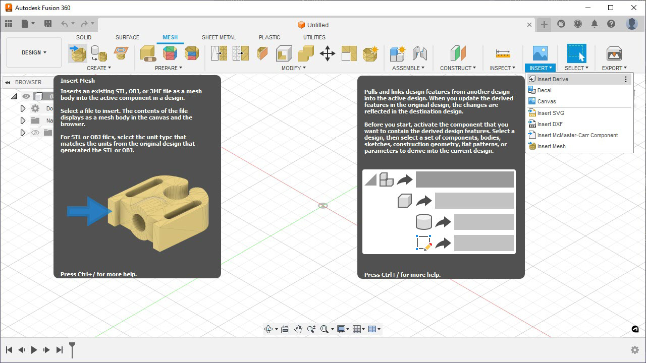
Figure 1.10 – Insert Mesh versus Insert Derive
If you are inserting a single mesh (STL or OBJ) file, you will have the ability to edit the location and units for that mesh file at the time of insertion. If you import multiple mesh (STL or OBJ) files, the location and unit data you edit during the insert operation apply to all the files you insert simultaneously. Because of this, my preferred method is to insert the mesh files individually so that I can visually inspect them and edit their location and units one at a time, especially if I insert mesh files created by different designers, as they may have used different unit systems and coordinate systems.
Now, let’s focus on the Insert Mesh command and some of its options. For this first exercise, we will insert the CLIP.STL file. After initiating the Insert Mesh command and selecting the STL file, you will see the INSERT MESH dialog, with options to change the units and reposition the part. The Flip Up Direction button rotates the part around the X axis by 90 degrees. The Center button moves the inserted mesh by referencing the center of its bounding box to the origin of the active component. The Move To Ground button translates the mesh body so that its lowest point touches the ground plane. In Figure 1.11, the ground plane is the XY plane:
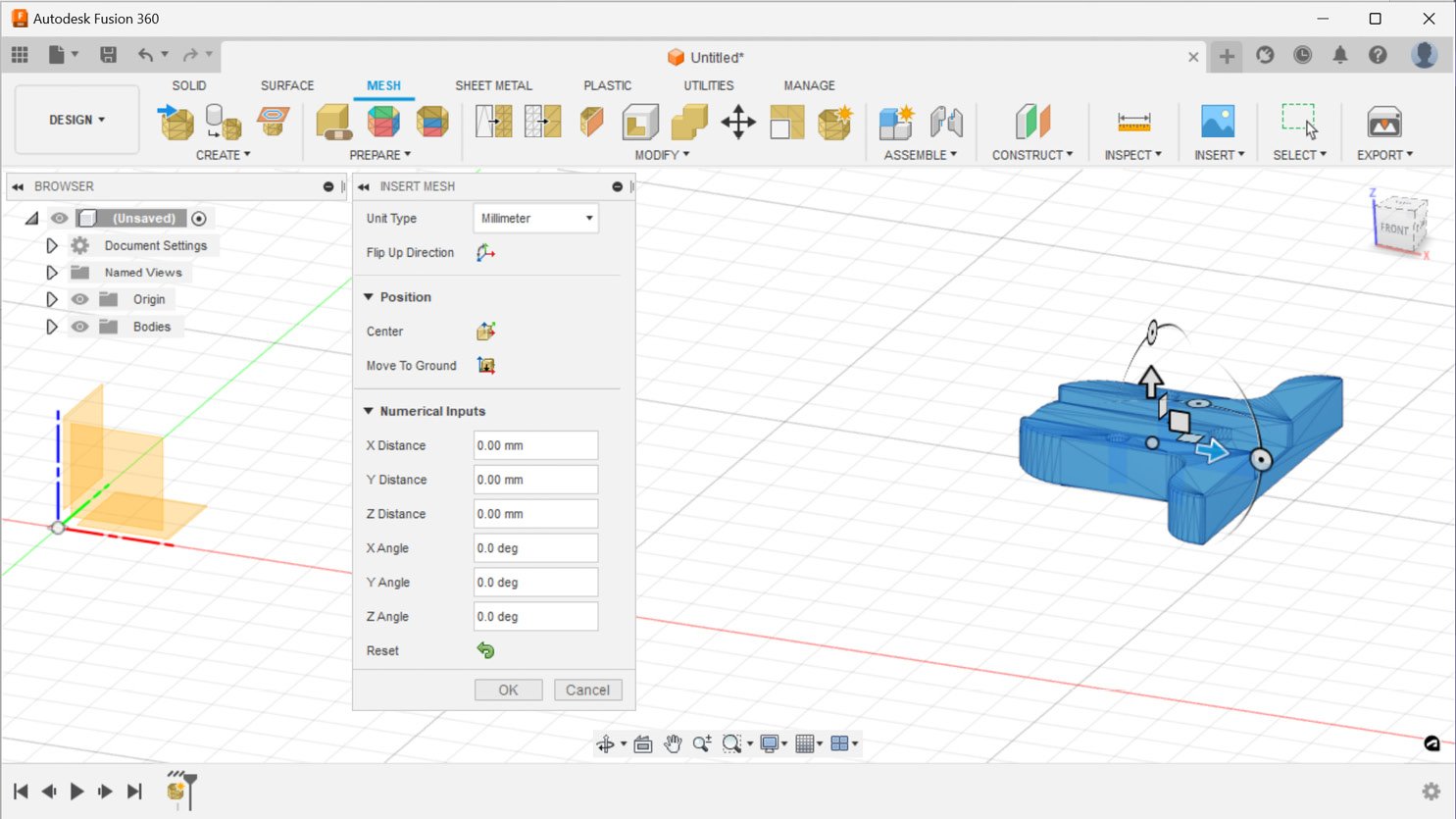
Figure 1.11 – The INSERT MESH dialog
In addition to centering and grounding a mesh body, we can also use the in-canvas manipulators (arrows and rotation tools) or the numerical inputs section within the INSERT MESH dialog to reposition the mesh body until we are satisfied. We can always revert our actions with the Reset button.
In this example, let’s first use the Center command, then the Move To Ground command, and press OK.
Important note
The default model orientation can be set in Fusion 360’s Preferences dialog in the General section. This book will rely on the Z up orientation for all examples.
The default units for every new design can be set in Fusion 360’s Preferences dialog in the Default Units section’s Design subsection. This book will rely on millimeters as default units for all new designs.
The default state of design history can be set in Fusion 360’s Preferences dialog in the General section’s Design subsection. This book will rely on Capture Design History (parametric modeling) for all new designs.
All these preferences can be seen in Figure 1.12:
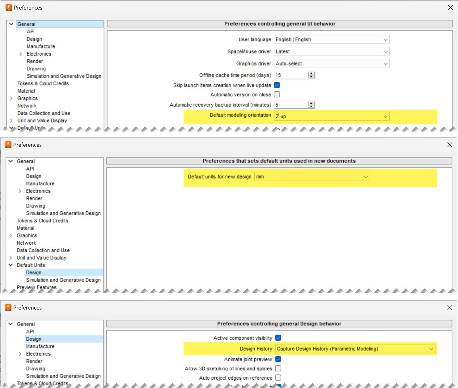
Figure 1.12 – Various sections within Fusion 360’s Preferences dialog
After we finish inserting this STL file, we will be left with a base mesh feature added to the timeline, and the mesh body located on the XY plane will be centered around the origin, as you can see in Figure 1.13:
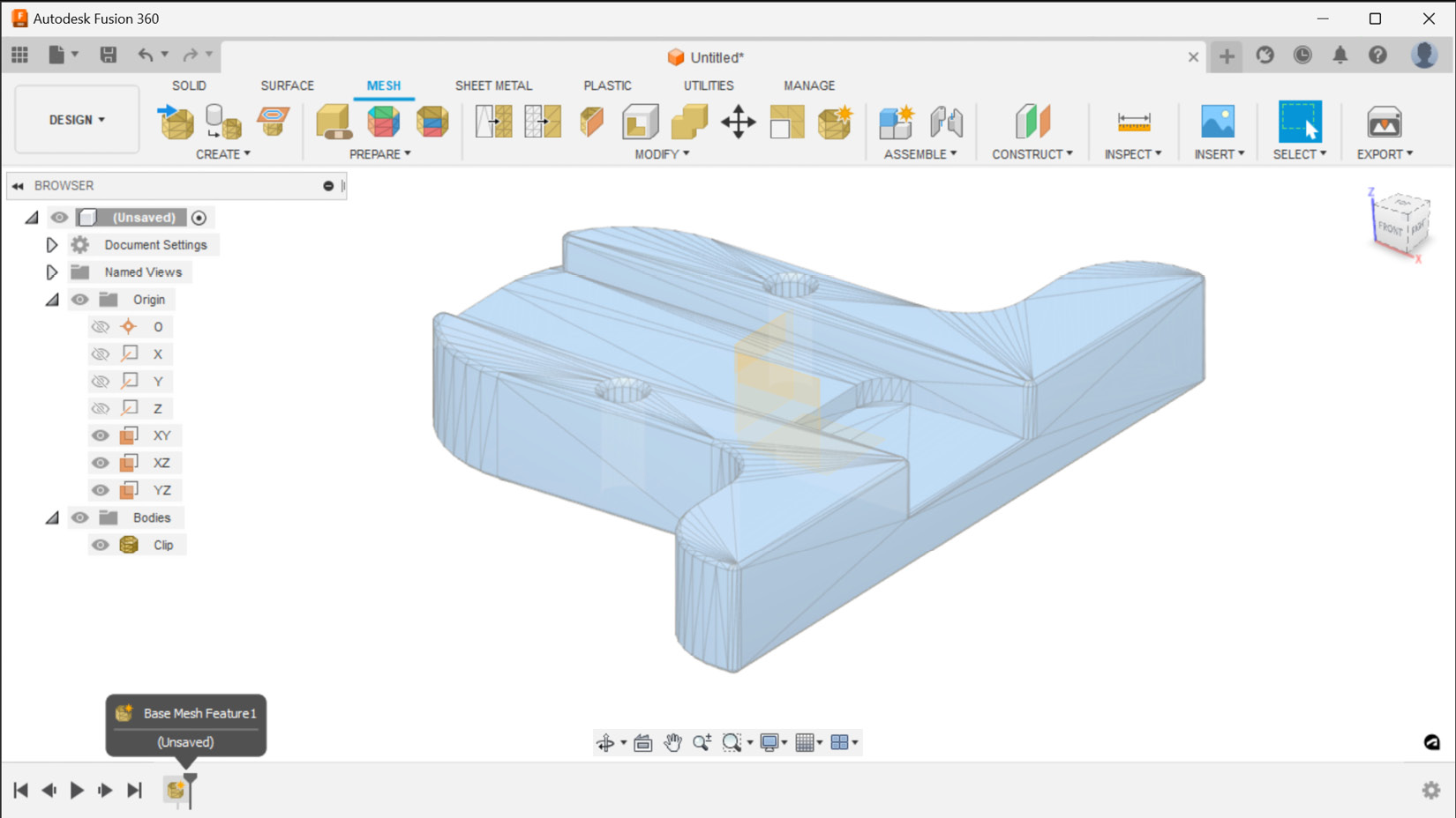
Figure 1.13 – The Insert Mesh command completed
Unlike STL files, 3MF and OBJ files can also contain color information. Now, let’s insert the CLIP.3MF file using the same Insert Mesh command into a new design file. In Fusion 360, we can create a new design file by selecting the + icon to the right of our list of open Fusion design documents. After inserting a 3MF file, Fusion 360 shows the mesh body with a unique color for each face group. A face group is a collection of faces that typically represent a feature or a region on a mesh body. This 3MF file is made of a single face group. Therefore, we will see a single color on all the faces after inserting this file into Fusion 360. We can visualize the color information contained within the 3MF and OBJ files by toggling face group visualization, using the Display Mesh Face Groups command in the INSPECT panel, as shown in Figure 1.14:
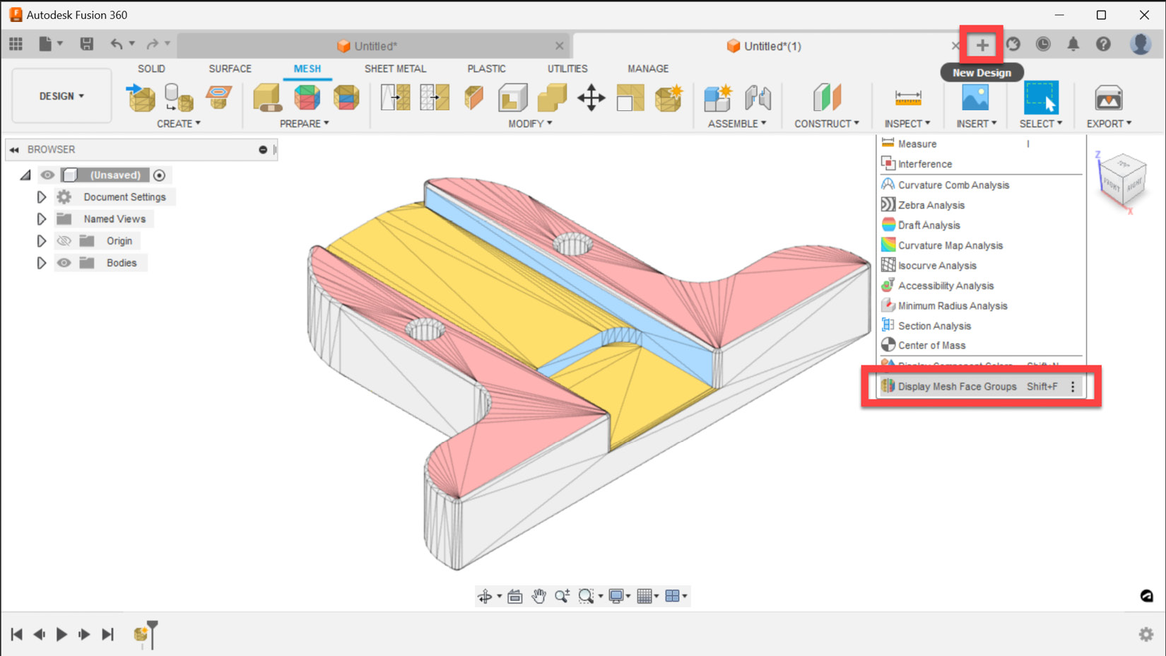
Figure 1.14 – 3MF and OBJ files can contain color
Important note
As shown in Figure 1.15, the Apply a different appearance checkbox must be unchecked in Fusion’s Preferences dialog | General section | Material subsection, in order to display color information contained within a 3MF or OBJ file opened in Fusion 360, using the Insert Mesh workflow previously described.
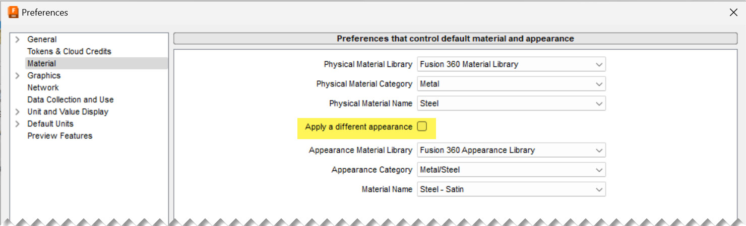
Figure 1.15 – The Material subsection in Fusion 360’s Preferences dialog
In this section, we learned about the various methods we can use to insert mesh files such as STL, OBJ, and 3MF. We also covered how to set units and relocate mesh bodies during the insert workflow. In addition, we went over how to visualize the color/texture data for those files.
Now, it is time to start focusing on workflows specific to inspecting mesh bodies we insert for potential problems and repairing them. In the next section, we will learn how to utilize the automatic inspection and repair functionality within the Mesh tab and start exploring how to manually repair Mesh bodies when the automatic repair is not enough.
Inspecting Mesh bodies and repairing them
STL is a simple file format and is widely used in 3D printing. Almost all 2D and 3D design software has been able to create STL files since its invention back in 1987. Because of its simplicity, long history, and wide availability, most STL files in existence contain errors and are generally in need of repair before they can be used for manufacturing.
In this section, we will learn how to inspect the mesh bodies we insert into Fusion 360 and how to repair broken STL files using automatic and manual repair techniques, in order to prepare them for 3D printing.
To demonstrate the various methods we can use to inspect and repair mesh bodies, we will use an STL file called Clip_Broken.STL. Let’s start by creating a new Fusion 360 design, as shown in Figure 1.14.
Now, we can use the Insert Mesh command and insert the Clip_broken.STL file into our active Fusion 360 design document. Just like the last example, let’s utilize the Center and Move To Ground functionalities in the Insert Mesh dialog consecutively to translate the part closer to the origin and above the XY plane. Now, we can look at the details of the mesh body we just inserted.
Fusion 360 automatically inspects all mesh bodies inserted and displays a warning icon next to any problematic mesh body. As shown in Figure 1.16, if you expand the bodies list in the browser, you will see a mesh body named Clip_Broken, and next to it, you will see a warning icon. If you hover over the warning icon, you will see the following information about the mesh body:
- Mesh is not closed.
- Mesh is not oriented.
- Mesh does not have positive volume.
When we see such information, we often need to take repair actions before we can proceed to 3D-print the files:
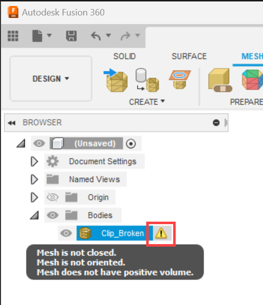
Figure 1.16 – A warning icon next to a problematic mesh body
Another useful tool for inspecting problematic mesh bodies is the PROPERTIES dialog. If you select a given mesh body, right-click, and select Properties, you can see a detailed list of information about the mesh body, as shown in Figure 1.17.
In this example, you can see that this mesh body does not have a mass or volume, even though it has been automatically assigned a physical material (Steel) with a density. This is another indication that this mesh body does not enclose a volume. Refer back to Figure 1.15, which shows the logic behind the automatic material assignment within the Material subsection of the Fusion 360 Preferences dialog.
Important note
A common term used in 3D printing to describe bodies that properly enclose a volume is watertight. Having a watertight body is a desirable feature when attempting to 3D-print objects. However, just because an object is not watertight does not mean it is not 3D-printable. In metal powder bed fusion 3D printing, support structures are often made up of surfaces (not watertight bodies). We will cover this topic in more detail in Chapter 12.
If you expand the Mesh subheading, you will see that this mesh body has two shells. A shell is a collection of triangles (and sometimes quadrilaterals) that are connected to one another. If a mesh body is made up of multiple shells, it often indicates a broken continuity of the triangles that make up a mesh body.
Sometimes, a mesh body can have multiple shells and still be valid. For example, imagine a hollow sphere. In such a case, you would have one shell that represents the outside of the sphere and another shell that represents the inner boundary.
If you expand the Mesh Analysis subsection, you will see that this mesh body is not closed, not oriented, and does not have a positive volume:
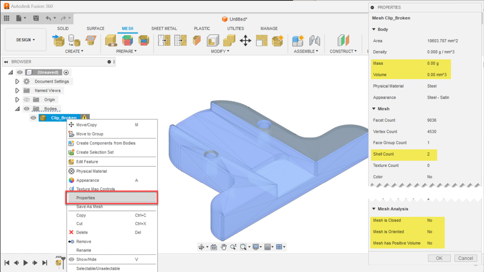
Figure 1.17 – The PROPERTIES dialog shows the relevant mesh analysis information
Now that we understand we have a problematic mesh body on our hands, we can close the PROPERTIES dialog, and select the Repair icon on the ribbon in the MESH tab | the PREPARE panel.
Fusion 360 has four automatic repair types. Let’s start by selecting the Close Holes repair type, which fixes flipped triangles and closes holes. If we activate the preview checkbox within the REPAIR dialog and expand the detailed analysis, we can edit the sliders to see the impact of the selected repair type on the body we wish to repair. Figure 1.18 shows that this repair type will automatically fix the part so that it can be 3D-printed, but a visual inspection of the outcome looks cluttered, with many triangles overlapping each other.
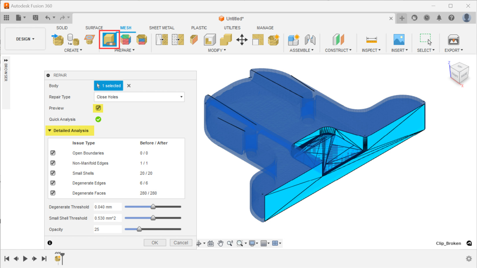
Figure 1.18 – The Close Holes repair type and its impact on this part
Even though the outcome of this automatic repair is reported as a success, it is always a good idea to perform a visual check and review the details of the mesh body properties. Figure 1.19 shows the PROPERTIES dialog for the Clip_Broken mesh body after we performed the Close Holes repair type. Here, we can see that this mesh is made up of 66 shells. This is an unexpected outcome, and a visual inspection of the part shows problematic zones, as highlighted in red ovals. This part is a symmetrical part along the XZ plane, yet the automatic repair closed one of the holes instead of creating the desired countersink hole type outcome:
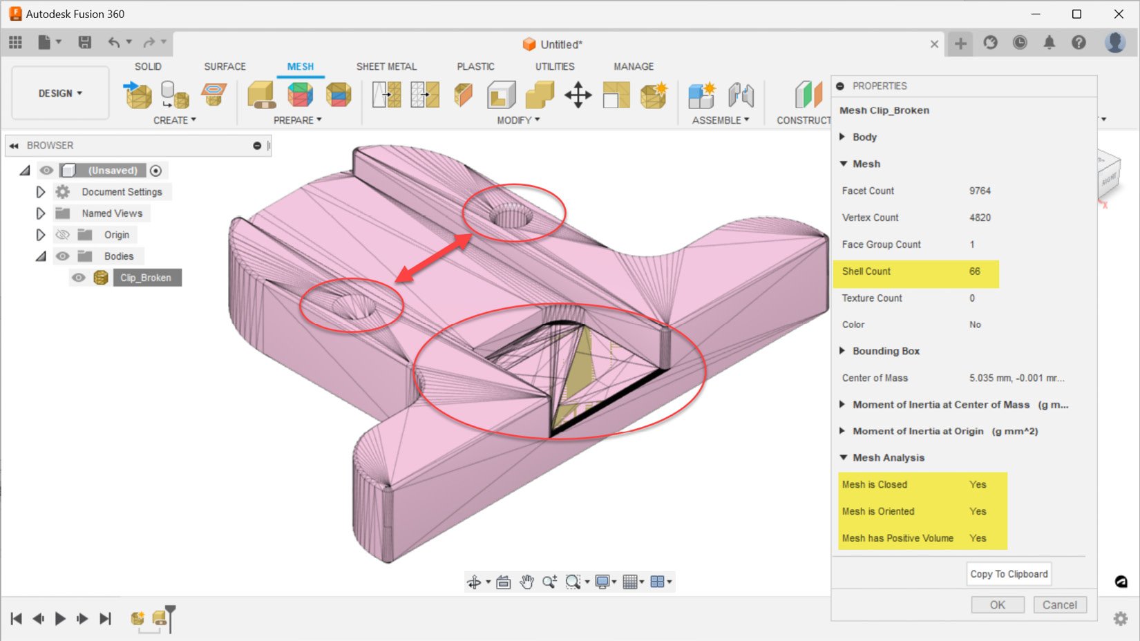
Figure 1.19 – The PROPERTIES dialog shows the outcome of repaired mesh body
Now, let’s use the Edit Feature command on the repair action we just performed, by selecting it from the timeline at the bottom of Fusion 360’s user interface and right-clicking on it, as shown in Figure 1.20. This time, we can change our repair type to Stitch and Remove. This repair action includes all the repairs that the previous repair type executed, and stitch triangles remove double triangles and degenerate faces, as well as tiny shells. Using this repair type takes a little bit longer, but the outcomes look much better. As you can see in Figure 1.20, we no longer look at a cluttered mesh in the region highlighted with the large red oval. However, we still have the same issue of not having the desired outcome of the countersink hole:
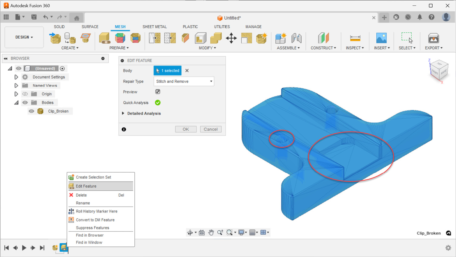
Figure 1.20 – The Stitch and Remove repair type and its impact on this part
Before we move on to the next repair type, let’s take a closer look at our part by adding a section analysis. To add a section analysis, we must use the Section Analysis command located in the INSPECT panel. After we select the cut plane as the XZ plane and flip the segment we want to section, we can easily see that this mesh represents a hollowed-out object, as shown in Figure 1.21. Looking at our part with a section analysis, it makes more sense why we saw a shell count of two within the PROPERTIES dialog:
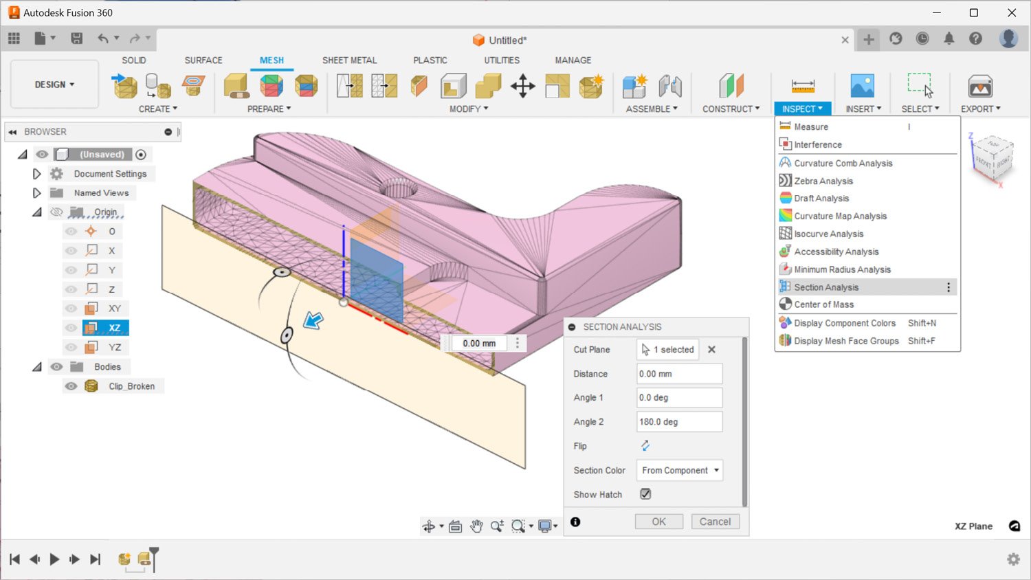
Figure 1.21 – A section analysis shows this mesh body is a hollow object
While the section analysis is visible, as denoted by the gray eye icon next to Section1 in the browser, we can edit our repair from the timeline and utilize the third repair type, called Wrap. This repair type makes the same repairs as Stitch and Remove and wraps the surface of the mesh body, removing all inner structures. As you can see in Figure 1.22, the outcome of this repair type removes the secondary shell inside our part, making our body a solid object. In this example, our goal was not to make such a drastic change to this part. Therefore, we will edit the repair one more time and move on to the fourth option. However, in some cases where the inner shell is also in need of major repair, this repair type could easily remove the triangles that belong to the inner shell, speeding up the mesh repair steps:
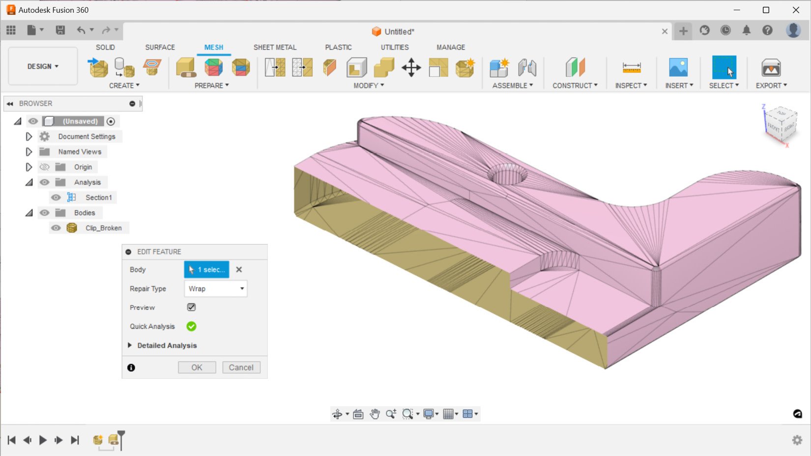
Figure 1.22 – The Wrap repair type and its impact on this part with a section analysis view
The fourth and final repair type is called Rebuild. There are multiple rebuild types available, and in Figure 1.23, you can see the outcome of a fast rebuild type with an average mesh density. This repair type reconstructs the mesh body and is the slowest repair type based on your density input. It can be used as a last resort when automatically repairing parts. However, the mesh outcome of this repair type has a high triangle count, and this repair type does a less desirable job of capturing details around sharp edges.
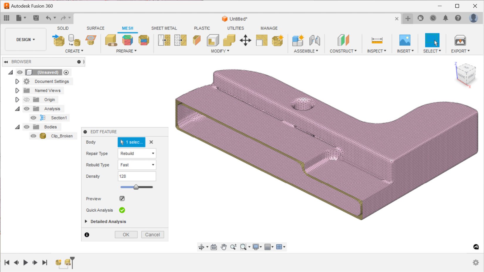
Figure 1.23 – The Rebuild repair type and its impact on this part with a section analysis view
Now that we have covered all four repair types, let’s edit a repair action, reuse the Stitch and Remove repair type, as its outcome was the most desirable for this part. This repair type also happens to be the default repair type recommended by Fusion 360.
None of the repair types were able to detect and repair the missing surface around the countersink hole. It looks like we will have to do some manual mesh editing actions to fix this issue. Let’s start by cutting the part in two, using the Plane Cut feature located in the MODIFY panel. The Clip_Broken mesh body is the body we will select to cut, and the cut plane will be the XZ plane. We will use the Trim type to remove the unwanted section and use the Minimal fill type to turn the remaining mesh body into a watertight object.
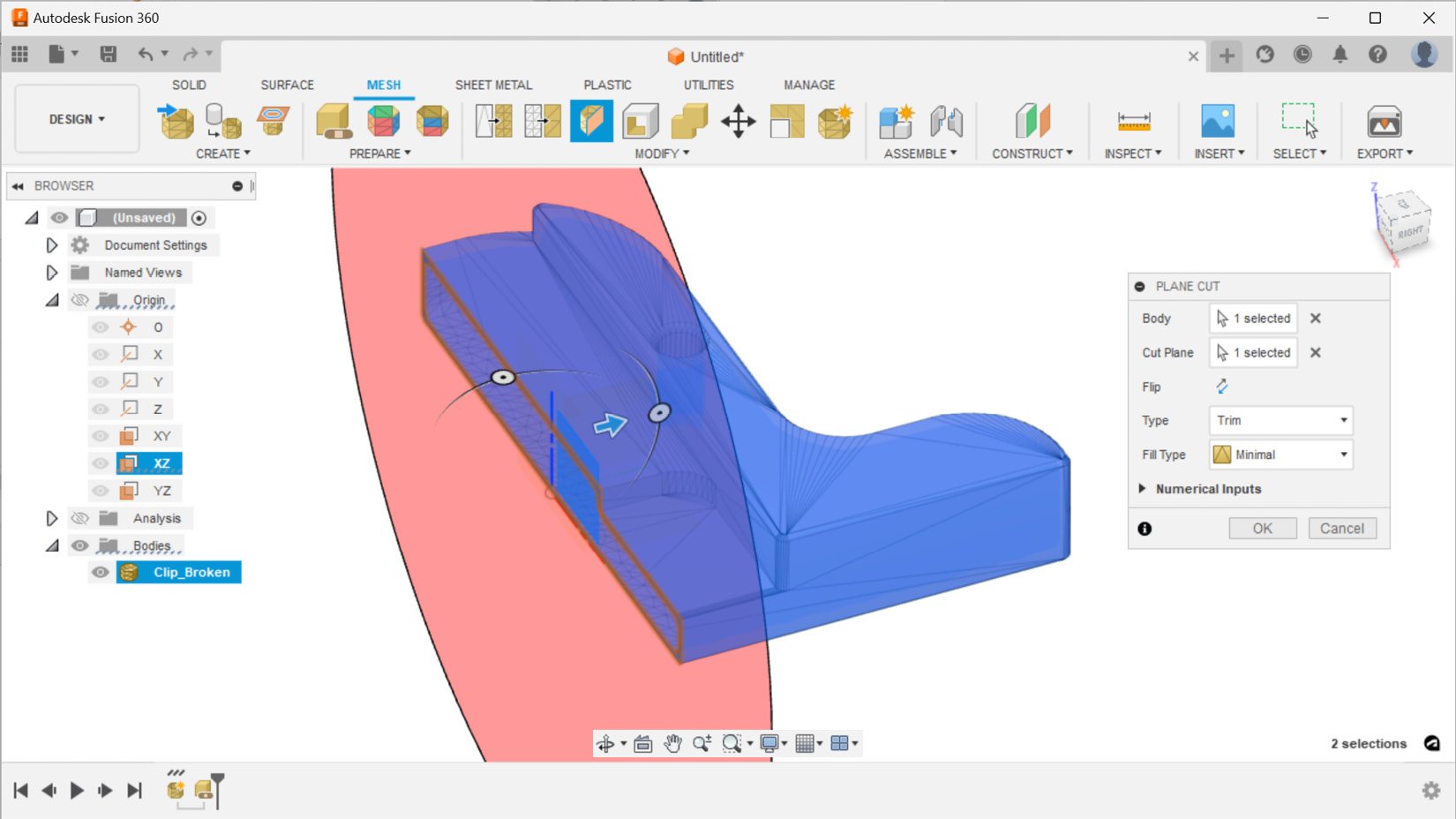
Figure 1.24 – Trimming the mesh body using the Plane Cut tool
Once we have cut the mesh body in half, we will have to create a component from the mesh body in order to mirror it. Figure 1.25 shows how to create a component from a trimmed mesh body – by right-clicking on it in the browser and selecting the Create Components from Bodies option.
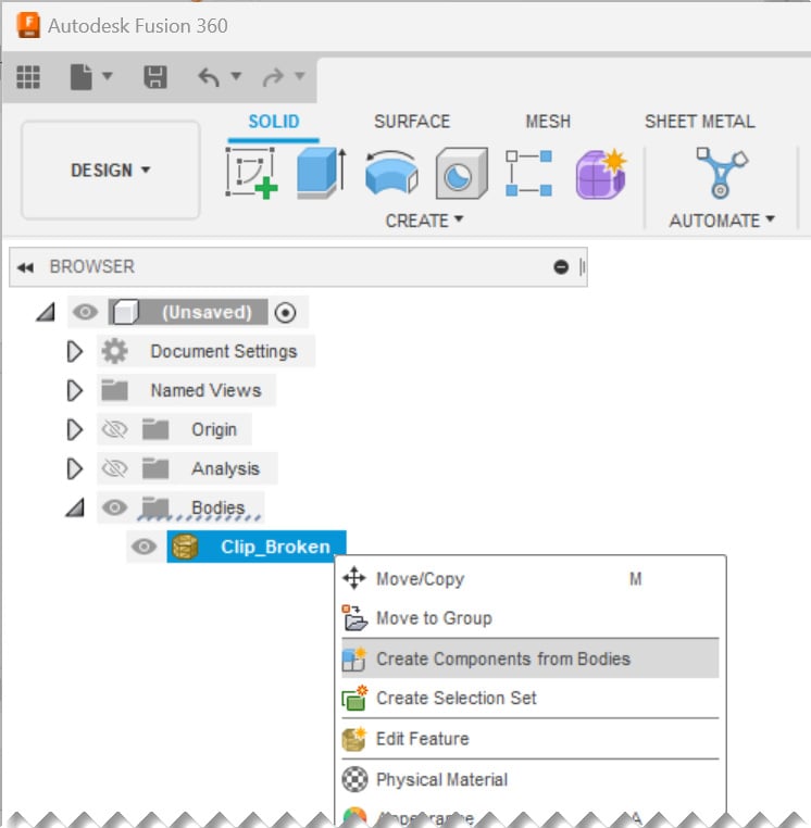
Figure 1.25 – Creating a new component from the trimmed mesh body
Once we have a component, we can toggle to the SOLID tab. We can select the Mirror command located under the CREATE panel. Once the MIRROR dialog is visible, we will have to change our object type to Components and select the newly created component to mirror. Our mirror plane will once again be the XZ plane. The outcome of the mirror action can be seen in Figure 1.26:
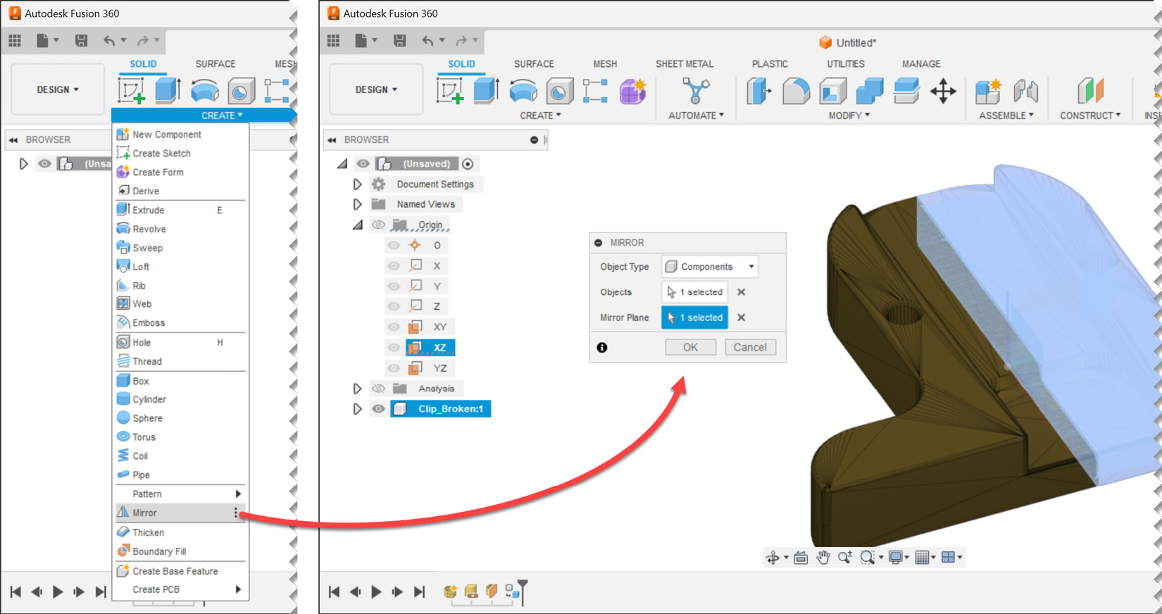
Figure 1.26 – Mirroring a component
After we mirror our component, we will end up with two mesh bodies within two components. It is time to combine them into a single unified component. To accomplish this, let’s go back to the MESH tab and utilize the combine command located within the MODIFY panel. We will have to select a target body and a tool body, which will be the Clip_Broken mesh bodies from the two components. We will utilize the join operation, create a new component, and keep the tools. This will ensure that we can easily compare the outcome and the input if desired in the future. Figure 1.27 shows the necessary input to combine two mesh bodies to make a new component:
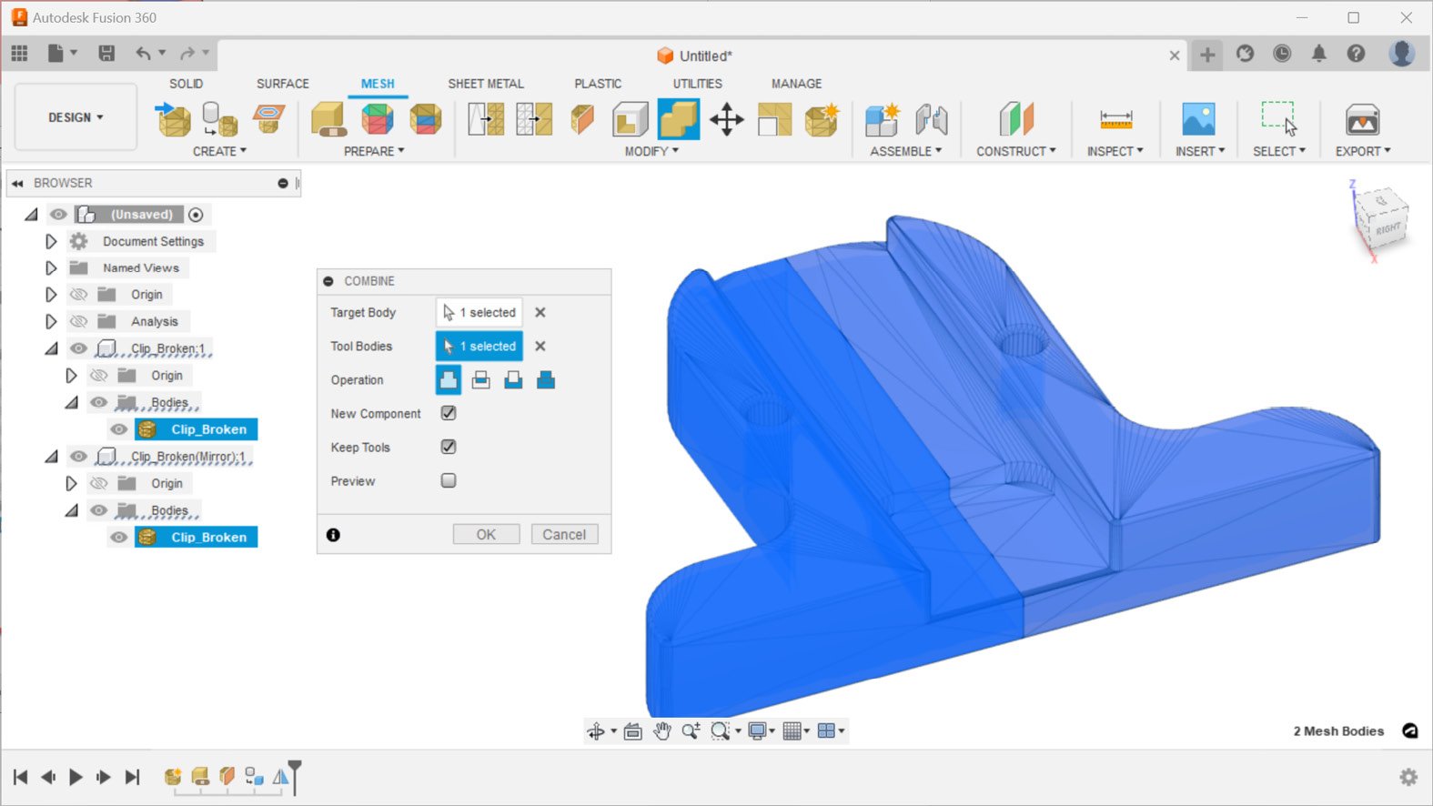
Figure 1.27 – Combining mesh bodies to make a new component
The outcome of the combined operation is a fully repaired body in a new component named Component3 in the browser. Figure 1.28 shows this new component while hiding the section analysis, as well as the first and second components:
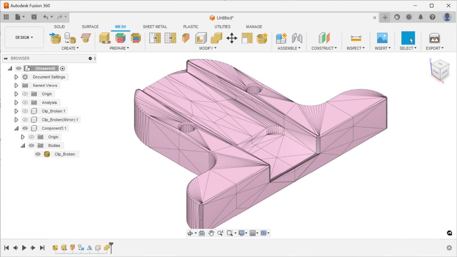
Figure 1.28 – Component3, a fully repaired mesh
If we turn on the visibility for the section analysis, we can quickly see that the mesh body we repaired still has a hollow cross-section and can be 3D-printed, as shown in Figure 1.29:
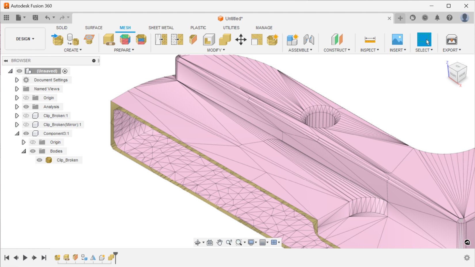
Figure 1.29 – A section analysis view of the repaired mesh body
As a final sanity check, it is always a good idea to look at the properties of the repaired mesh body to make sure we have a closed and oriented mesh with a positive volume. The timeline of all our actions is captured in the design history in the bottom-left corner of the browser, as shown in Figure 1.30. You can always replay those steps in the future and remind yourself how you were able to repair this mesh.
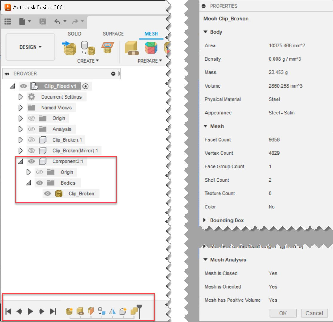
Figure 1.30 – The properties of repaired mesh and the repair actions timeline
The Git repository for this chapter also includes a Fusion 360 file called Clip_fixed.f3d, which you can open directly in Fusion 360 to replay the timeline if you had any issues during this example.
Summary
In this chapter, we learned about the various ways to open CAD and mesh files in Fusion 360, ranging from utilizing the File | Open... workflow to uploading files to Fusion Team from a web browser or the Fusion 360 desktop and mobile apps.
We also covered how to insert mesh files into our active designs, how to set the units, and how to position those parts. We highlighted how to render and color data contained in certain mesh files. We talked about how to inspect problematic mesh bodies. We also went through an example using both automatic and manual repair steps, such as trimming mesh bodies and mirroring components, to fully repair a heavily damaged mesh file.
Using the skills you learned in this chapter, you can now feel confident in your ability to open, inspect, and repair most mesh files using Fusion 360.
In the next chapter, we will go over how and why we may want to work with parametric modeling versus direct modeling. We will also cover how to automatically detect features for models we import to Fusion 360 and how we can edit those features with Design for Additive Manufacturing principles.
