Chapter 5. Getting Your Hands Dirty Using the GPIO Header
Here, we will start diving into the more physical side of cooking with the Raspberry Pi Zero:
Pin configurations and precautions for using the GPIO pins
Using the GPIOs with the WiringPi library
Connecting an LED with RPZ and controlling it using C, Python, and a shell
Basics of the UART port and getting data from the desktop on the serial port using Minicom
Writing a Python/C program to get UART data in your code
Basics of I2C and checking the I2C devices present on a port
Basics of SPI and setting up an SPI module
Converting a 5V signal into a 3.3V signal and slew rates
Running RPZ on a battery
Controlling GPIOs using a web interface
Making RPZ a radio transmitter and sharing music
Using a Node.js library to control the GPIOs
Interfacing the ESP8266 WiFi module with RPZ
The General Purpose Input Output Header, known as the GPIO, is one of the things that stands out compared to "normal" computers. The pins of the GPIO give you the ability to have your Raspberry Pi talk communicate with just about anything. Here are just a few things that can be leveraged with the GPIO Header:
Turning on and off LEDs, Motors and Speakers
Receiving digital inputs from sensors and monitors
Communicating with other computers over a serial port
Chaining multiple devices or sensors using different interface protocols
This is just a short list of what is possible, and once you get comfortable using the Raspberry Pi Zero GPIO, you'll be able to have it control or communicate with just about anything!
Pin configurations and precautions for using the GPIO pins
The general-purpose input/output, or GPIO, on the Raspberry Pi Zero is the port for interacting with the physical world. Not only can you control things such as motors and lights, but you can also read data from things such as thermometers or light sensors. The GPIO can read information or send commands, and you can use programs such as C or Python to handle the logic for what to do.
This is the point where we will start integrating other devices over the GPIO pins. While you don't have to do anything for this recipe except have your Raspberry Pi Zero up and running, you will probably want to attach a header and, ideally, a breadboard cobbler to prepare for the upcoming recipes.
The most important thing to remember when using your Raspberry Pi Zero is that the GPIO has no voltage regulation. If you push too much power over GPIO, you could end up with BSOD, or Blue Smoke of Death (also commonly referred to...
Using the GPIOs with the WiringPi library
The WiringPi project is a library written in C that makes it easy to work with the GPIO. It has been actively updated with each board revision, includes command-line utilities, and has several wrappers available in higher-level languages such as Ruby and Python.
For this recipe, you will want to install the GPIO libraries for the Raspberry Pi. You might already have them installed, but it is easy enough to make sure it is installed and upgraded, with the following commands:
sudo apt-get install wiringpi
sudo apt-get upgrade wiringpi
You'll also want to get the Python wrapper installed, which you can do with this command:
sudo pip install wiringpi2
Note
If this command fails, first try sudo apt-get install python-dev.
Once you have the libraries installed, you will have a new command-line utility, gpio. Unplug anything you have connected to your GPIO pins and give it a test.
Let's start with gpio -v:
pi@rpz14101:~ $ gpio ...
Basics of the UART port and getting data from the desktop on the serial port using Minicom
We used the GPIO pins for the serial port to contact the Raspberry Pi from a desktop computer in an earlier chapter. Physical pins 8 and 10 (BCM GPIO 14 and 15) for transmit (TX) and receive (RX), respectively, can also be used to talk from your Raspberry Pi Zero out to other devices. Let's explore the Universal Asynchronous Receiver/Transmitter (UART) a bit further.
For this recipe, all you'll need is your Raspberry Pi Zero and a jumper wire to connect your TX and RX pins.
This is about as simple a setup you can have, but it is a typical way to verify you've set up your Raspberry Pi Zero to communicate outbound over serial. By default, the Raspbian OS has configured your GPIO's TX and RX to expect and handle incoming serial communication. If you connected from a desktop to your RPZ with a USB-to-serial adapter in Chapter 2, Setting Up Physical and Wireless Connections then...
Writing a Python/C program to get UART data in your code
While Minicom might be fine for real-time communication with a device, if you need something to continuously talk to your device or react when a certain message is received, you'll want to put together an application for that. Python of course has great libraries for serial communication, which makes it a good choice for managing or automating communication between two devices.
The previous recipe gets you set up for serial communication by freeing up the serial port bindings and virtual console for incoming serial communication. If you have finished the first recipe, you can use the same configuration to try out communication with serial.
Python can work with serial connections with a library named-you guessed it-serial! For this recipe, we will just perform a simple test to open and close the connection via serial.
Here, we will run a few commands to initialize, open, and view the status of the serial connection...
Basics of I2C and checking the I2C devices present on a port
I2C is an interface mode on the Raspberry Pi's GPIO that allows communication with all kinds of peripherals. We will be using one of these later on in this chapter when we transmit radio signals. This recipe will show you how to set it up and test it.
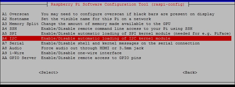
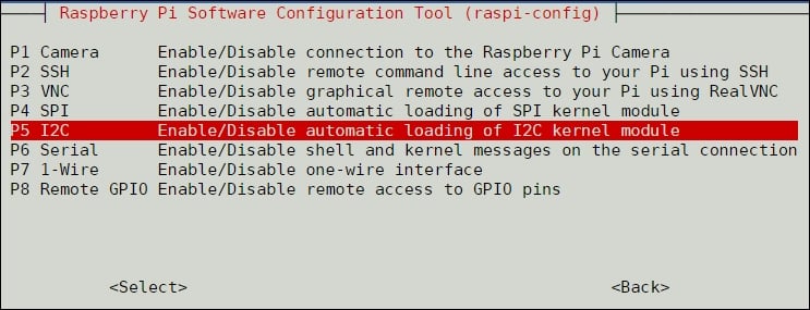
The easiest way to configure the use of the I2C interface is with raspi-config. Enter sudo raspi-config and select Interfacing Options. Option P5 will set up I2C communication. Select Enable, reboot, and you are ready to begin. Older versions of Raspbian have I2C in the Advanced Options Menu, as shown below:
Finding I2C in older Raspbian versions
The newer releases of Raspbian have an Interface Menu, where you will find the I2C settings:
After enabling I2C and rebooting your Raspberry Pi, take a look at the device list:
pi@rpz14101:~ $ sudo ls /dev/*i2c*
/dev/i2c-1
Installing i2ctools will give you a few more options when working with the I2C interface...
Basics of SPI and setting up an SPI module
The SPI, or Serial Peripheral Interface, is similar to the I2C bus, but has a few advantages for a few more wires. Generally, you'd choose I2C or SPI based on the peripheral you are trying to talk to and what protocol it supports. For this recipe, we will look at configuring SPI for upcoming recipes.
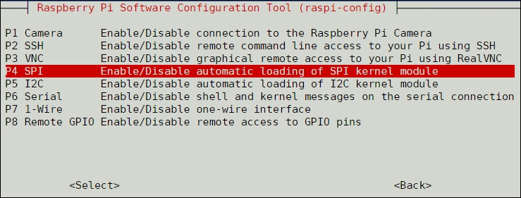
Just like setting up I2C in the previous recipe, the easiest way to get going is with raspi-config. Run with sudo, and select Interfacing Options. Select P4 to enable SPI, and reboot.
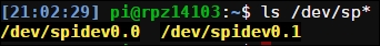
Once you've enabled SPI and rebooted, you should find your bus on the device list:
Working with the SPI module is a little bit more complex than I2C, but it gives you more flexibility as well as expandability to run multiple peripherals over the same bus. This will be a lot of fun later, but for now, let's look at the pins you will be using. Just like any connection to your Raspberry Pi Zero, the Power and Ground pins will be the same, but...
For prototyping, using a regular AC power source or desktop computer is the way to go. Once you've come up with some ideas for projects, perhaps outdoor temperature monitors or humidity sensors in your attic, you might find that there isn't AC power available.
Now that you know how to run your Raspberry Pi Zero wirelessly, with a battery source, you could run it as a low-profile, remote system. There are dozens of different things you can do with a wireless, battery-powered computer and a few sensors-your only limitation is how long your batteries can run.
Depending on how simple, long-lasting, or low-profile your solution is, there are a few different options.
USB battery packs have become common, small, and inexpensive over the years. This is the easiest and most advisable way to go: you just connect the battery pack to the micro-USB power input on the Raspberry Pi Zero. This way, you have all of the voltage regulation and protection of...
Controlling GPIOs using a web interface
You've been writing programs and running command-line tools and utilities to get things done, because you are the Raspberry Pi Zero expert! While it isn't too hard, you don't necessarily want to write and run a program each time you want to turn on a motor or light or take a sensor reading. For this recipe, we are going to see how we can control the GPIO bus from a web page, being served by a web server on your Raspberry Pi Zero.
For this recipe, we will continue using Python, but with a new library called Flask. Flask is a micro-framework for rendering Python programs into web pages, and it will work perfectly for creating a web-based GPIO controller. If you already have python and pip updated and configured, the command should be as simple as the following:
sudo pip install flask
After that, we jump right into coding!
In your ch5 directory, create a new directory called templates with the mkdir command:
mkdir /home/pi/share...
Making RPZ a radio transmitter and sharing music
For this recipe, we are going to really apply all we've learned, reconfigure our Pi for audio output, and send that out to a radio transmitter. You'll have your own Raspberry Pi radio station!
For this recipe, I used the Adafruit Si4713 FM radio transmitter; it's inexpensive and works great. If you want to run audio directly from your RPZ's audio out, you'll also need the following parts:
2 100 Ohm resistors
2 300 Ohm resistors
2 10uF capacitors
2 22pF capacitors
Jumper wires
If using only the Si4713 and the built-in audio jack, you just need to have I2C enabled, which we covered in the I2C Basics recipe earlier in this chapter. If you are wiring the audio directly from the Pi, you will also need to make some changes to the pin configuration. By default, the Raspberry Pi Zero's audio output is not associated with any physical GPIO pin. We can reassign them easily with a reboot so that the PWM0 and PWN1 alternate pins serve audio. With...
Using a Node.js library to control the GPIOs
When you are controlling the GPIO on your Raspberry Pi Zero, you aren't just limited to Python for building web pages. Node.js is a popular, portable JavaScript server that includes its own package manager and GPIO libraries. Generally speaking, it is also a little more common than serving web pages from Python.
For this, we will be using the popular Node.js and Node Package Manager, or npm. We'll also be using node-red, which is a node-based graphical GPIO configuration tool. This should all be installed with a default Raspbian build, but in case it isn't, you can install the packages individually with apt-get:
sudo apt-get update
sudo apt-get upgrade
sudo apt-get install nodejs
sudo apt-get install npm
Next, you will want to install the rpi-gpio package. I had some trouble with this, and had to install node-gyp before I could get the rpio-gpio package to install. Running the following worked great:
sudo npm install node-gyp
sudo...
Interfacing the ESP8266 WiFi module with RPZ
Earlier in the book, we covered a hack for taking a USB Wi-Fi adapter and hard-wiring it to the Raspberry Pi Zero board. This works just fine, but you can also configure Wi-Fi communication over the GPIO port! Truly, the Raspberry Pi's flexibility in configuration is astounding. In this hack, we will connect and play around with the inexpensive and popular ESP8266 to get our RPZ talking over Wi-Fi. We will also use some of the skills we picked up in earlier recipes talking over the GPIO serial bus to open the door to even cooler hacks!
You don't need much for this except your Raspberry Pi Zero and the ESP8266. The one I used was from Adafruit, called the ESP-12-E, but there several options available. I would go with anyone that is already mounted to a board for prototyping, unless you are planning to solder it to a custom-made circuit board to attach to your Raspberry Pi Zero. If not, you'll need some jumper cables and a breadboard...