
Understanding tessellation parameters
First of all, what is tessellation? Tessellation is a process where 3D CAD models are converted into 3D mesh models. This conversion is needed for 3D printing in order to calculate toolpaths.
In the following figure, on the left, we have a solid CAD model where the circle profiles are perfectly rounded, and on the right, we converted the model into a mesh via tessellation:
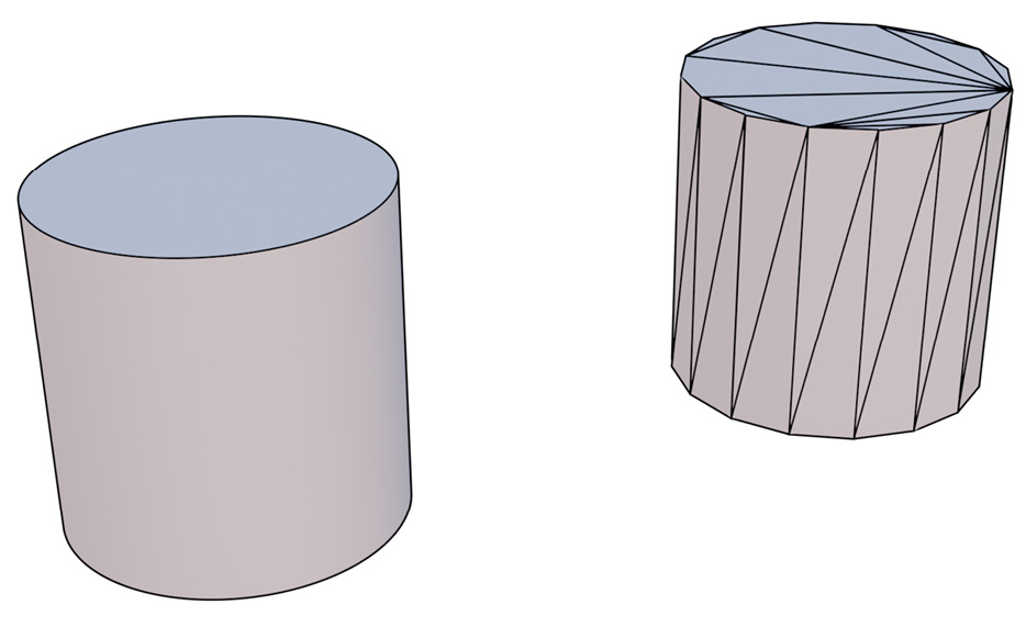
Figure 17.25: CAD geometry versus mesh geometry
The main difference between these two types of 3D geometries is how they are defined; CAD models are based on rigorous math equations and they can describe every shape without losing details. Mesh models, on the other hand, are based on a finite number of vertices and faces connected by edges.
Long story short, tessellation always loses details in the conversion process; that’s why it is important to understand how to set it properly. If the tessellation is too rough, we may end up with...