Most of the sensors use the standard 3-axis coordinate system to represent the sensor values. This coordinate system is similar to the 3-axis coordinate system used to measure the length, breadth, and height of any 3D object in space, along with the difference of the frame of reference and the orientation of the 3-axis. As depicted in the following figure, the origin of this coordinate system lies in the center of the screen. When the device is in its default orientation (generally the portrait mode), the x axis is in the horizontal direction with the right-hand side having positive values and the left-hand side having negative values. Similarly, the y axis is in the vertical direction and the z axis is coming out of the phone screen. Points above the origin in a vertical direction are positive, and the ones below the origin in vertical direction are negative for the y axis. Similarly, the points coming out of the screen are positive, and the points behind the phone screen are negative for the z axis.
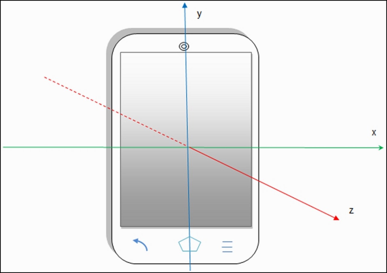
This particular x, y, and z axis orientation stands good for all the devices that have their default orientation as portrait mode, as shown in the previous figure. But for any device, especially tablets, the orientation of the x and y axes are swapped when their default orientation is in landscape mode. The z axis' orientation remains the same. So, before making any assumption about the orientation of an axis, it's always a good practice to confirm the default mode of the device. In this coordinate system, we always use the device's frame as a point of reference. The device coordinate system is never changed or swapped, especially when the phone is moved or rotated in any direction. The OpenGL (Graphic library) uses the same coordinate system and rules to define its values.
Some position sensors and their methods use a coordinate system that is relative to the world's frame of reference, as opposed to the device's frame of reference. These sensors and methods return data that represents the device motion or device position relative to the earth. The Orientation Sensor, Rotation Vector Sensor, and getOrientation() method use the world's frame of reference coordinate system, while all the other position, motion, and environmental sensors use the device's frame of reference coordinate system.
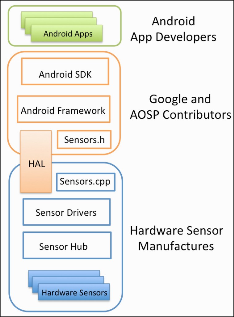
The following figure represents the layers in the Android Sensor Stack. Each layer in the sensor stack is responsible for a specific task and communicating with the next layer. The top-most layer consists of Android Apps, which are the consumers of the data from sensors. The second layer is the Android SDK layer, through which the android applications can access the sensors. The Android SDK contains APIs to list the available sensors to register to a sensor and all the other sensor functionality. The third layer consists of the Android Framework, which is in charge of linking several applications to a single HAL client. The framework consists of various components to provide simultaneous access to multiple applications. It is discussed in detail in the next section. The fourth layer is called HAL (Sensors' Hardware Abstraction Layer), which provides the interface between the hardware drivers and the Android framework. It consists of one HAL interface sensor and one HAL implementation, which we refer to assensors.cpp. The HAL interface is defined by the Android and AOSP (Android Open Source Project) contributors, and the implementation is provided by the manufacturer of the device. The Sensor Drivers are the fifth layer of the stack, and they are responsible for interacting with the physical devices.
In some cases, the HAL implementation and the drivers are the same software entity, while in other cases, the hardware integrator requests the sensor chip manufacturers to provide the drivers. The Sensor Hub is the sixth optional layer of the stack. The Sensor Hub generally consists of a separate, dedicated chip for performing low-level computation at low power, while the application processor is in the suspended mode. It is generally used for sensor batching and adding hardware FIFO queue (which is discussed in detail in the Wake locks, wakeup sensors, and FIFO queue section of Chapter 4, Light and Proximity Sensors). The final seventh layer consists of the physical hardware sensors. Mostly, they are made up of the MEMS silicon chip, and they do the real measuring work.