
Understanding infill parameters
In this section, we will cover all the options to manage the inner areas of our part – in particular, the infill geometries and their specifications:
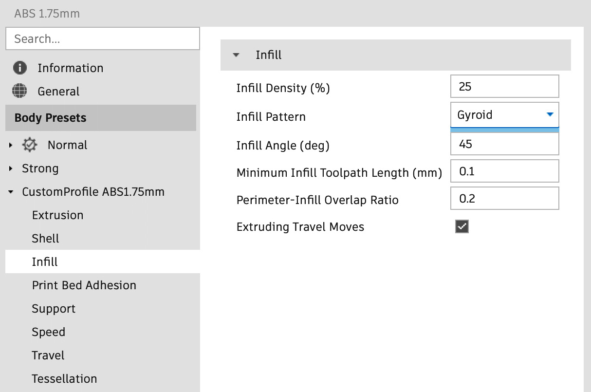
Figure 17.15: Infill panel
Let’s look at the options:
- Infill Density (%): This is the amount of infill material printed. A value of 100% will result in a solid part, while a value of 0% is an empty shell. Usually, this value is set around 30%, depending on the loads applied on the part.
As we can see in the following figure, changing the infill density can drastically change the part weight and strength as well as the printing time:
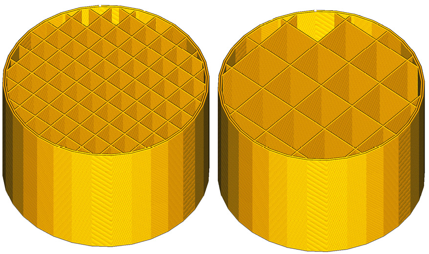
Figure 17.16: Infill percentage
The part on the right features infill geometries with a density of 10%, while the part on the left has an infill density of just 20%. This means that the inner structures of the part on the left are twice as strong, but also twice as heavy and take twice as...