
Attaching and reading a distance sensor
First, we will wire in and secure this sensor to the robot. We will then write some simple test code that we can use to base our behavior code on in the next section. After completing this section, the robot block diagram should look like Figure 8.7:
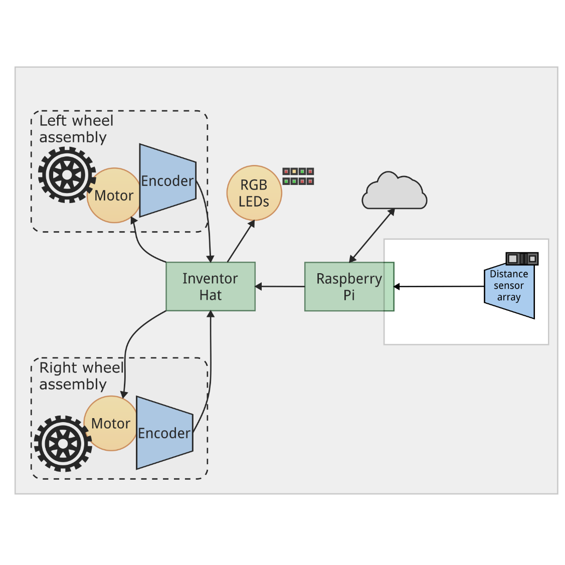
This diagram builds on the block diagram in Figure 5.19 from Chapter 5, Building Robot Basics – Wheels, Power, and Wiring, by adding the sensor. It has an arrow to the Raspberry Pi, since although it is an active sensor, the information from it is logically flowing from the sensor to the Raspberry Pi. In the next section, let's attach the sensor to the robot chassis.
Securing the sensor to the robot
Our sensor needs to be pointed to the front of our robot; it needs to not fall off and move rigidly with the chassis. The chassis doesn’t have front-facing bolt holes; however, in the suggested purchase list, we have the...