


Reviewing the Basics
SketchUp is known for being an easy software to pick up and start using. In fact, it is probably safe to say that most users are self-taught! One of the issues that many users run into when they teach themselves, be it through online videos or via third-party books, is that they take away only what they need at that moment. This means that there is more to learn when it comes to the basics.
In this chapter, we will take a look at some of the basic functionality in SketchUp and dive into how to get the most out of a few commands. Yes, things such as extensions and creating custom shortcuts are important, and we will be covering those items in future chapters. While it would be great to do a comprehensive review of every way that every command can be used, we will have to settle for a few specific use cases. This chapter should serve as a spark to get you to think about how to get more out of the native input and editing commands. This knowledge will be the base upon which you will grow your SketchUp expertise!
In this chapter, we will cover these main topics:
- Navigating in SketchUp
- Exploring edges and faces
- Getting more out of Move
- Deforming geometry
- Diving deep into Follow Me
Navigating in SketchUp
One of the main things that makes SketchUp so easy to work in is the fact that you are always moving through your 3D model. Unlike other 3D modeling programs, SketchUp allows you to navigate in 3D space without the use of special viewports or widgets to change how you are viewing your model in 3D space.
Basic navigating can be thought of as three distinct pieces:
- Orbit
- Zoom
- Pan
The great thing about the way the SketchUp navigation is set up is that you can use the Orbit and Zoom commands without leaving the input or modification command you are currently using! In fact, depending on the hardware you are using, you can change the views of your model while in the middle of creating or modifying geometry.
The navigation commands can be used in one of three ways, depending on your hardware. It is generally accepted that the best way to navigate in SketchUp is with a three-button mouse, but it is possible to do it with a standard two-button mouse or with a trackpad:
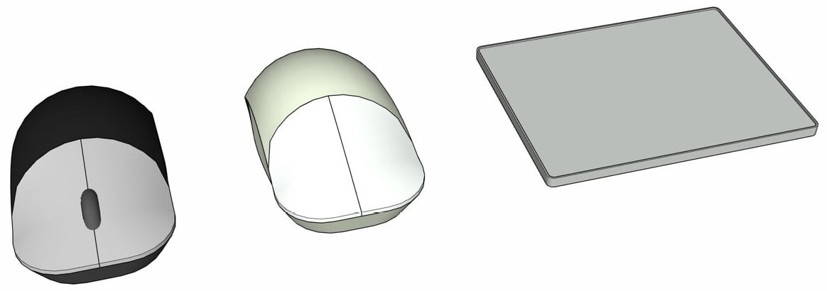
Figure 1.1 – Left to right, a three-button mouse, a two-button mouse, and a touchpad
When we talk about using a three-button mouse, we are talking about a mouse with a trackwheel in the middle of the left and right mouse buttons. While not actually a third button, the track wheel allows quick access to both zooming and orbiting commands with one finger, which can be a huge time-saver while designing. In the next sections, we will talk about how to use the commands with any of the hardware mentioned and which ones might be preferable.
It may seem odd to learn how to use any navigation technique other than the primary one (if you have a three-button mouse, why learn to use a trackpad for navigation?), but any SketchUp master knows that you cannot depend on hardware alone. I have many stories about needing to open or modify a model while on the go with no place to use my mouse, having to navigate with a touchpad, or using SketchUp at a customer site where only an old two-button mouse was available. Knowing how to use any of the hardware options will ensure your ability to move through a SketchUp model, regardless of your input device.
Speaking of Hardware Options…
We will be discussing using other hardware such as tablets or 3D mice in Chapter 10, Hardware to Make You a More Efficient Modeler.
Navigating with the Orbit, Zoom, and Pan icons
Obviously, your primary focus when using SketchUp will be to create and edit 3D geometry. While this will be the primary focus of most of this book, it is important to stop and look at the commands you will use more often than any input command or tool – the navigation commands:
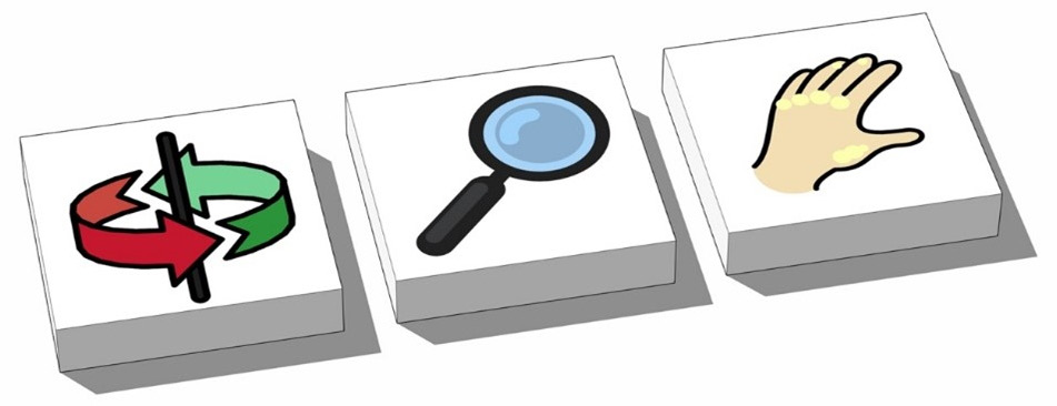
Figure 1.2 – The Orbit, Zoom, and Pan (hand) icons are part of the default toolbar
Regardless of your input hardware, you can always use the Orbit and Zoom icons to move through your model. The best part about using these icons is that you can use them in the middle of any command. Once you are done, you will be returned to where you were before you clicked the icon. Let’s give it a try:
- Use the Rectangle command to draw a rectangle on the ground.
- Click the Push/Pull icon on the Standard or Large toolbar.
- Click and release on the rectangle.
The face of the rectangle should move up and down on your screen as you move your cursor. Now, let’s see what happens when you start using the Orbit command.
- Click the Orbit icon on the toolbar.
Notice how your Push/Pull state freezes? This will allow you to spin around your model without having to finish the Push/Pull command. The Push/Pull is paused until you complete your Orbit.
Click and Release or Click and Drag
Unless otherwise noted, input and editing should be done by click and release, rather than clicking and dragging. While SketchUp will allow you to do either in many cases, click and release will allow you to do things such as change your views or add modifiers to a command without having to hold down the mouse button the whole time.
While in the Orbit command, you can click anywhere on your model and use that point as a handle to spin your entire model in 3D space.
Centering Your Orbit
Notice that the camera spins around the center of your view. How you orbit around your model will depend on how your model is situated in your current view. This may mean using a combination of Zoom, Pan, and Orbit commands to get to the ideal view of your model.
Remember, while it can seem as though you are moving a piece of your model, it is important to remember that you are actually spinning the entire 3D workspace. You are effectively moving your camera, or your view of your 3D model, and not the geometry in the model.
Now that we have finished orbiting, let’s get back to Push/Pull.
- Click on the Push/Pull icon again.
Notice how you are back to Pushing/Pulling the face of the original rectangle? Remember, entering the Orbit command will temporarily suspend the current command and return you to it once the orbit is complete.
Let’s give Zoom a quick try! While still dragging the face of the rectangle around, activate the Zoom command.
- Click on the Zoom icon.
Notice how the Push/Pull freezes again and you click and drag the magnifying glass up and down your model to zoom in and out? Once again, you can click back on the Push/Pull icon to return to your command.
- Click on the Push/Pull icon again.
Another command that you may want to learn to use via the toolbar is Zoom Extents. This command will blow the model up as large as it can get on your screen. This can also be clicked at any point during input or editing. Unlike the Orbit and Zoom commands, you cannot access this command via hardware; the toolbar icon or menu command is the only way to use Zoom Extents.
Finally, the Pan icon (the one with the hand) can be used to grab your model by a point and move it around without turning it. Pan moves the entire model normal to your view, so instead of spinning around your model, you will be moving straight up, down, and side to side. Just like Zoom and Orbit, the Pan command will suspend your current action until you return to the command you were originally in.
Navigating with a touchpad
Anyone designing on a laptop has had that experience when they have had to whip out SketchUp on the go and take a look at a model using just the hardware on the laptop. While many laptop users rely on an external mouse as their primary means of input, there are those special few who actually prefer to use a touchpad when they can!
Using a touchpad to navigate is a process of combining modifier keys or buttons with gestures on the touchpad. These keys will vary depending on your operating system:
- To orbit your model on a Windows computer, hold down the middle button.
- On a Mac, hold down the Control and Command keys.
Just like orbiting with the buttons, the active command suspends until you are done moving. The advantage of using this process is that you don’t have to click back to the command to resume. As soon as you release the middle button/modifier keys, you are just back in the command!
Zoom works in very much the same way, except you do not need to use any keys. Regardless of the operating system, you can zoom in or out by sliding two fingers up or down the touchpad.
To pan while using a touchpad, you will add a modifier key to Orbit. Just as with Orbit, the modifier key will change depending on your operating system:
- To pan your model on a Windows computer, press Shift while orbiting (middle button and Shift).
- On Mac, press the Shift key while orbiting (Control + Command, and Shift).
I know that this can seem like a lot of keys to hold down, especially on a Mac, but with a little practice, it really can become second nature.
Navigating with a three-button mouse
It has been said that the best hardware is the hardware that you have available to you. This is mostly true, but many SketchUp users will say that the best input device to use is a three-button mouse. The reason is the third “button.” With the scroll wheel, you can instantly start orbiting or zooming without the need to press any keys or click any toolbar icons.
To zoom, you only need to roll the scroll wheel up and down. The point that is under your cursor at the time that you start scrolling will be the center of your zoom. You will zoom in or out of that single point.
Zooming Direction
Zooming direction is controlled by the operating system. You may need to modify your system settings to toggle between Natural and Reverse scrolling. This will change whether scrolling up is a zoom-in or a zoom-out. Neither one is inherently better for SketchUp. Use the one that feels the most natural for you.
To orbit with a three-button mouse, you simply have to press down on the scroll wheel. While holding the scroll wheel, you will move the entire model in 3D space. The location that your cursor was at when you pressed down on the scroll wheel will act as a handle to spin the model around.
Middle Mouse Button
System settings and hardware drivers may give you the option to program the middle button. This can be a great way to add functionality to your mouse, but for SketchUp, it is important to have the scroll wheel click set to middle button. Without it, you will not be able to orbit using the scroll wheel.
Finally, panning is performed by pressing the Shift key while in orbit. Double-clicking the scroll wheel over any point in the model will pan the model to center that point on your screen.
The best way to navigate in SketchUp
With practice, any one of the input devices mentioned previously can become efficient tools for navigating SketchUp. Far and away though, most users find that a three-button mouse allows them to spend less time getting to the view they need and more time actually modeling. If you have been using a touchpad or a two-button mouse (or a one-button mouse, yikes!), you should consider getting hold of a three-button mouse. The addition of a button dedicated to moving your model in 3D space is a huge time-saver and will help navigating to become second nature.
Now that we have covered how to navigate through a SketchUp model, let’s dive into what actually makes up a SketchUp model.
Exploring edges and faces
When it comes to what a model is made of in SketchUp, there are really only two pieces: faces and edges. I know that, eventually, you will end up with a model with groups, curves, polygons, and components, but those are just containers for edges and faces, which are building blocks that make up anything and everything that can be created in SketchUp:
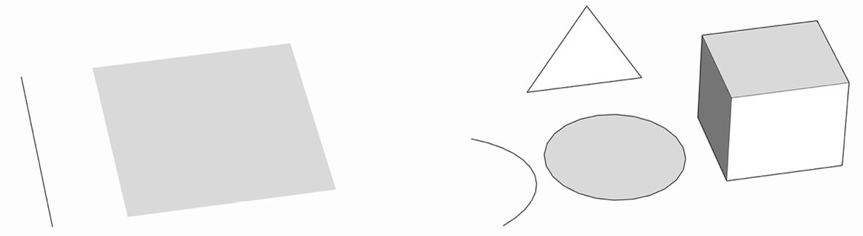
Figure 1.3 – Edges and faces (left) make up everything on the right
For this reason, it is very important to understand how these items are created and work together in order to gain mastery of the 3D modeling process.
Edges are lines, right?
Technically, this is a true statement. Edges are a connection between two points in 3D space. In SketchUp, we call them edges because they generally define one or more faces, and the term line is reserved for a specific command.
Edges are created when you use any of the input commands but are most simply created using the Line command. The Line command, of course, connects two points in 3D space with a single edge. This can be useful for creating boundaries of faces or breaking them into smaller pieces.
Edges also make up curves, arcs, and circles. While you do not have to draw each individual edge when you create one of these entities, it is very important to note that they are all made up of a series of edges.
Edges in arcs and circles
When you use the Circle command or any of the Arc commands to draw a curved line in a model, you are actually creating a string of connected edges. In fact, any of these commands will allow you to define the number of edges before or after a circle or arc is created. The measurement box in the lower right of your screen will allow you to enter the number of sides before you start drawing. Once an arc or circle has been created, you can edit the number of segments in the Entity Info window. Changing this number will increase or decrease the number of edges drawn while keeping the geometry in the same place with the same curve.
Welding edges
In SketchUp, you can select any number of edges and weld them using the right-click menu. Once one or more edges are welded, SketchUp will recognize them as a curve. A curve is a series of connected edges that are selected together and recognized as a single entity. This is different from an arc or circle though, as you cannot edit the number of segments in a curve, nor can you modify how many edges make up the curve, as shown here:
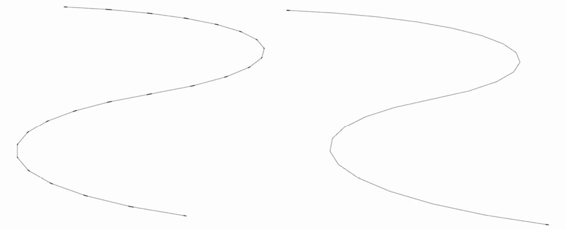
Figure 1.4 – With endpoints visible, you can see the difference between the segments on the left and the single-piece curve on the right
Let’s do an experiment:
- Use 2-Point Arc to draw an arc with the default 12 edges of any size.
- Select the arc and look at Entity Info. See how it calls it an arc and you have an editable Segments field?
- Now, right-click on the arc and select Explode Curve from the context menu.
Look at the Entity Info window now. You now have 12 edges selected. The option to modify the number of segments is gone.
- Finally, right-click on the highlighted edges again and choose Weld Edges from the context menu.
The Entity Info window now shows that you have a curve selected. It also tells you that the curve has 12 segments, but the field is disabled. This means that while you get to know how many edges are in the curve, you cannot modify that number.
So, why would you ever want to explode curves or weld them back together? The truth is, that sometimes, the modeling process will cause curves to explode. Intersecting geometry can break curves and circles and leave you will a bunch of disconnected edges. Using Weld Edges will get them to stay connected, making them easier to work with. This will also affect how these edges work with a command such as Push/Pull or Follow Me. There may also be times that it serves your model to have those edges broken apart rather than stay connected. The important thing to remember is that all this geometry, arcs, circles, and curves, is simply made of a series of edges that can be broken apart or put back together as needed.
Face or a surface?
A face is created any time three or more edges connect in a single plane. Unlike some other file formats, SketchUp faces can be made of any number of sides and may contain holes. As soon as an edge breaks a face into more than one piece, it becomes multiple faces.
If one or more faces are connected at the edge and that edge is smoothed (either using the Eraser with the Smooth modifier key or using the Soften/Smooth window) they will merge together, forming a surface. A surface is any number of faces that have been connected by smoothed edges. If you select a surface, the entire surface will be highlighted. If you choose to show hidden edges (from the View menu), you will see the hidden edges as dashed lines. In this view, you will be able to select individual faces, despite them being part of a surface.
It is important to know the difference between the two as certain commands, such as Push/Pull, cannot be used on surfaces. However, you can use Push/Pull on individual faces when hidden edges are visible!
Crossing faces
When you draw an edge across another edge, they break at the intersection. One edge crossing a second edge will result in four total edges, meeting at one central point. The same is not true for faces. Try this example:
- Draw a rectangle on the ground.
- Pan over and draw a vertical rectangle. Use the Right Arrow key to constrain the rectangle to the red plane.
- Select the vertical rectangle by the midpoint of a vertical side.
- Move it so that it crosses the face of the first rectangle.
- Place the vertical rectangle so that the edges do not touch:
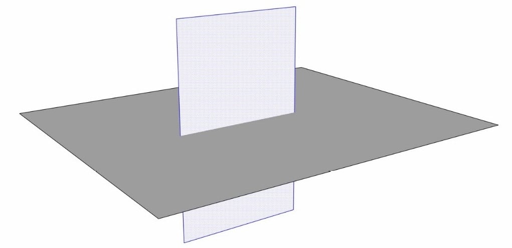
Figure 1.5 – Faces can cross without merging geometry
See how the rectangles cross over each other without merging together. At this point, you can select the vertical rectangle again by any point and move it out of the original rectangle. If you place the vertical rectangle so that the edge intersects any edge of the first rectangle, then the edges will become connected, and the faces themselves will still simply pass through each other.
To cause a face to intersect another face, you must tell it to intersect.
- With both rectangles crossing through one another, select both faces (use Shift + Select to highlight both).
- Right-click on either plane.
- Select Intersect Faces from the context menu.
- Select With Selection.
Notice how both faces are now broken where they cross each other. Edges will automatically connect to other edges, but faces will not.
As you advance with your 3D modeling skills, you will become more and more efficient using different native commands and extensions and will develop your own workflows for different types of models. The thing to remember though is that every single model is made of edges and faces. Knowing how these basic pieces work and interact is key to understanding how SketchUp works. Another key is in knowing how to use commands beyond their initial function. In the next section, we will see how to use a tool such as Move to perform multiple actions.
Getting more out of Move
Don’t worry, this is not the part of the book where the author encourages you to stand up and stretch before proceeding (but if you feel the need, go ahead, I will be right here when you are done). This is the part of the chapter where we do a deeper dive into using a few of the Modify tools.
More to Move than you remember
One of the biggest parts of moving from a beginner user to an intermediate user is learning to use the basic commands beyond their basic functions. Many new users only scratch the surface of what they can do with tools such as Move, Select, or Rotate.
The first thing you will need is a couple of pieces of geometry:
- Draw a rectangle on the ground.
- Use Push/Pull to create a box.
- Triple-click on the box to select all geometry.
- Right-click and select Make Group.
This will be a good piece of geometry to work with, but you will need to create a different group to work with as well. Next to the box, let’s create a cylinder.
- Draw a circle on the ground.
- Use Push/Pull to create a cylinder.
- Triple-click on the box to select all geometry.
- Right-click and select Make Group.
Now, you have some things to move! Let’s start by exploring the Move and Rotate options of a group.
- Use Select to highlight the new group.
- Select the Move command and move the cursor over the selected group.
At this point, you have a couple of options for moving this box. You can click anywhere on the highlighted group and use that point as a handle to move by. Clicking and releasing on any point will connect the group to the cursor by that point. Clicking and releasing a second time will place the group at the new cursor location. You can use any geometry in the group as an arbitrary move point, but if you pay attention, you can be much more exact in your selection.
Move your cursor over the cylinder group and look at the corners of the group. Notice how there is a circle on every corner? Clicking on one of these points will allow you to use the corner as a point by which to move the group. If you orbit to a three-quarter or isometric view of the group, you should see a point on the seven corners of the group that you can see. You should also notice that there is one more point that represents the corner of the group that you cannot see. If you move your cursor over that point, the geometry in the group will temporarily become transparent, allowing you to see and select the back corner.
This is great for geometry such as this cylinder that does not have geometry filling in the corner of the group as the box does:
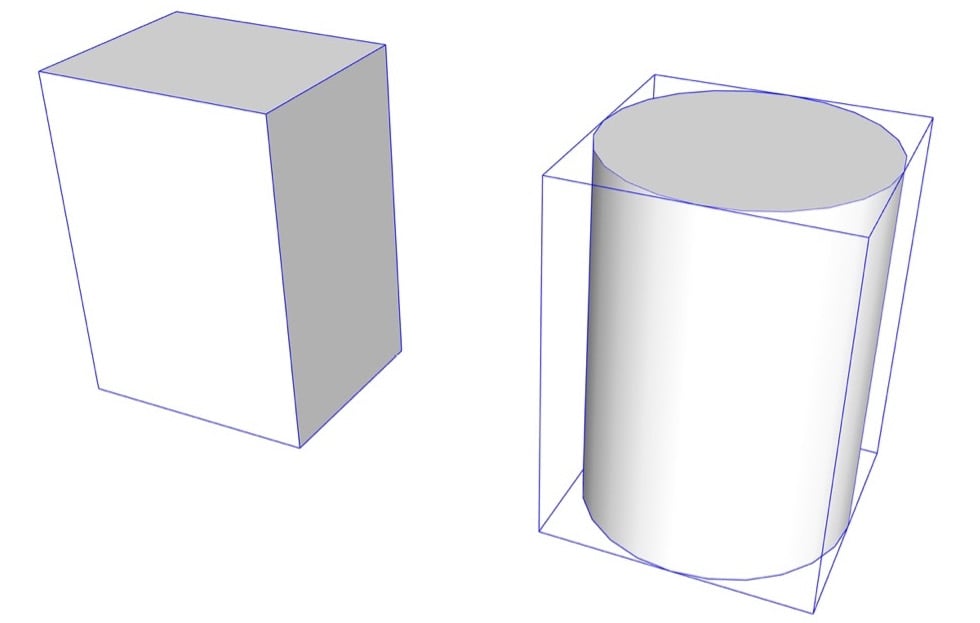
Figure 1.6 – The bounding box wraps tightly around the box while the cylinder does not reach the corners
But wait, there’s more! Look at the modifier keys listed in the status bar. If you press the key to toggle through grip types (Alt on Windows or Command on macOS), you can change the points visible on your group. Tapping the modifier key will toggle between the following point sets:
- Corners of group
- Midpoints of group edge
- Middle of group sides
- Center of group
Modifier Keys
We will be talking a lot more about using modifier keys in Chapter 3, Modifying Native Commands, which includes a comprehensive list of every modifier key for all commands!
Careful selection of the point you use to move items can save you a lot of time and energy. Clicking the correct start point when you are moving can allow you to complete the move in one go, rather than performing multiple moves to get your selected geometry exactly where it needs to be.
Copies and arrays
Move, like many SketchUp tools, can be used to perform more than just one action. For example, Move can be used to create an array of the selected item. Odds are good that you have learned to use the Modify command to copy before, but just to make sure, we will cover it quickly here:
- Use the Move tool to select the box.
- Move the box to the side (away from your cylinder).
- Tap the Copy modifier key (Ctrl on Windows or Option on macOS).
- Click on the new location and receive a copy of your box at this location.
- Now, before you click anything else, type
5Xand hit Enter.
Now, you have a total of five copies of your box. Each box is spaced the exact same distance as your first copy. This is referred to as an array in SketchUp.
Now, let’s say that you were hoping to have a total of five boxes. Typing 5X gave you five copies plus the original for a total of six. The good news is that as long as you do not start a different command or select different geometry, you are still in the array-making process! Let’s get rid of that extra copy.
- Type
4xand press the Enter key.
The extra copy is now gone! You can increase or decrease the number of copies by typing NUMBERX and hitting Enter as many times as you like, as long as you stay in the command.
This is the process of creating an external array. That is, the copies are placed one after another, external to the original move. Next, let’s create an internal array.
- Select the cylinder group and use the Copy modifier to move a copy a long way from the original in the opposite direction of the box group.
- Immediately after placing the copy, type
/4and press the Enter key.
In this case, the number of copies specified is placed, evenly spaced between the original and the copy. Just like an external array, you can change the number of copies by simply typing a new number.
- Type
/8and press Enter. - Type
/3and press Enter.
Using the native Move command with a few simple modifier keys makes it easy to quickly create a series of geometry. Just imagine how much more work it would be to place each copy in an array or, worse yet, recreate the geometry over and over! Understanding how and when to modify commands will help you become a faster, more efficient SketchUp modeler.
Radial arrays
This same process can be used with the Rotate command as well. Start a new model and let’s give this a try:
- Create a box and put it in a group.
- Use Move with the grip toggle to move the box so that its front bottom edge is at the origin.
- Then, move the box up the green axis.
- With the box still highlighted, select the Rotate tool.
- Select the origin as the center point of rotation.
As you start to rotate the box around the origin, press the Copy modifier key (Ctrl on Windows or Option on macOS).
- Rotate the copy around to the green axis on the far side of the origin (180 degrees) and click to place the copy.
- Type
/6and press the Enter key.
With that, you have created an internal radial array. The same rules apply here, as you can change the number of copies between the original and copy by simply entering a new number at any point.
The process of making an external radial array is just as simple.
- Use Undo to remove the copies from the previous step.
- Use Rotate to make your first copy 30 degrees from the original.
- Type
11xand press Enter.
Now, you know how to make a clock face!
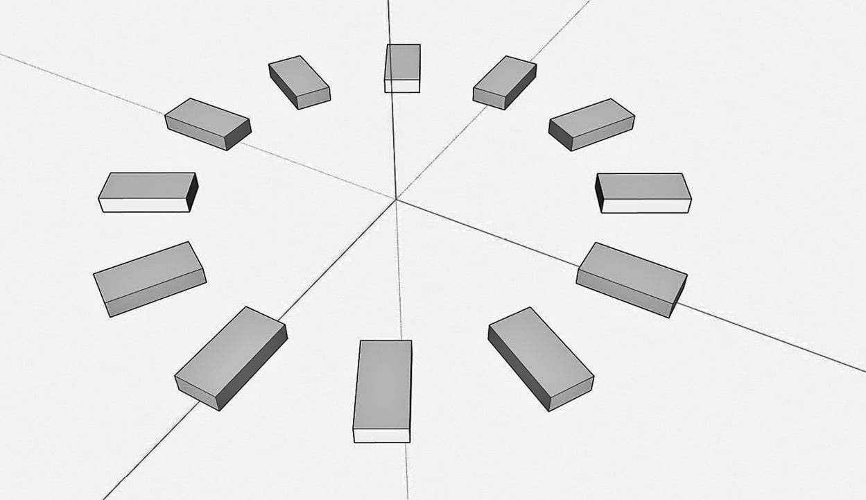
Figure 1.7 – A dozen boxes in an array around a central point is exactly how you would make a clock
The important thing to take away here is that the basic commands can be used to do more than their name will imply. Creating things such as copies of arrays using the Move or Rotate commands are simple ways to get more out of a single command. Before worrying about what extensions are out there to expand how you model, remember to explore everything that the native commands are capable of. We will be diving much deeper into this idea in Chapter 3, Modifying Native Commands. Up next, let’s take a look at how we can use Move and a few other native commands to create some organic geometry.
Deforming geometry
SketchUp is well known for allowing users to draw basic geometry (polygons, lines, and arcs, for example) quickly and easily. One of the biggest misconceptions about SketchUp is that if you want to go beyond drawing basic shapes or straight lines, you need to depend on extensions. While extensions are amazing (and we will be covering them in Chapter 11, What Are Extensions?) any SketchUp ninja knows that you can lean on the basic input and modification tools to generate advanced geometry quickly. In this section, we will see how to use native tools to deform basic geometry into any shape you need.
For this example, let’s get hands-on and draw a tree, something like the following:
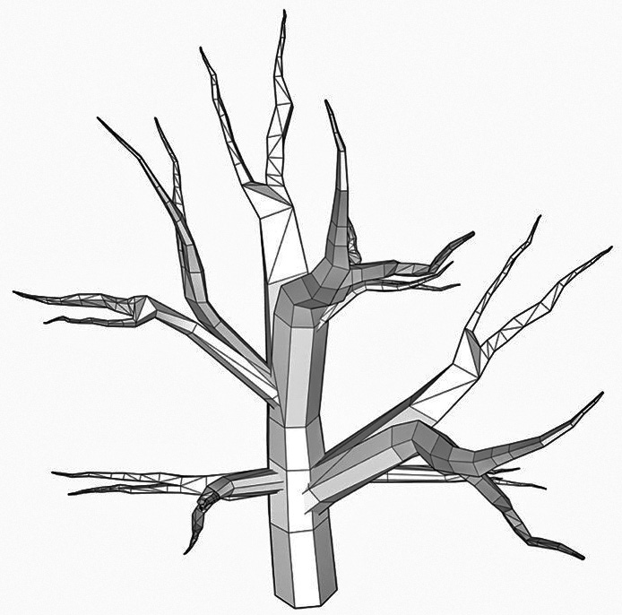
Figure 1.8 – Making a tree like this can be done using only native commands
Now, there will be a little bit of sculpting and using your creative abilities in this, but we will cover the basic steps that will allow you to create something like this using only native SketchUp commands.
Let’s open a brand new SketchUp model and dive into some tree modeling:
- Use the Polygon tool to draw an eight-sided shape on the ground (fairly large, as this will be the base of the tree).
- Use Push/Pull to pull the shape up.
- Select the top of your extruded octagon.
- Use the Scale command to shrink the polygon to around 90% of its original size.
- Select the Rotate tool to spin the top polygon 10 to 20 degrees.
At this point, you should have a basic looking tree trunk, something like this:
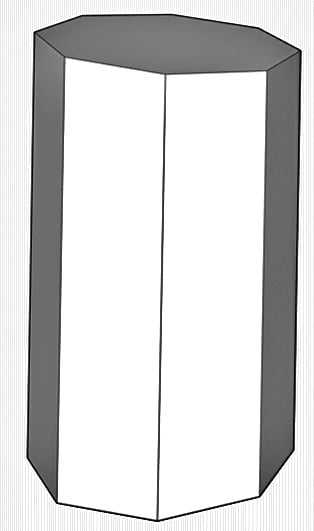
Figure 1.9 – Tree trunk
From here, we will do the same steps, but add another Rotate into the mix. In order to get a curve in the tree’s trunk, we will rotate the top shape out of the plane.
- Use Push/Pull to pull up the top of your trunk, then scale it just a bit (maybe to 95%).
- Now, use Rotate to angle the top polygon on the red axis (tap the Right Arrow key to lock in the red axis). You don’t need to rotate it a lot; 5 to 10% should look good.
More Inferencing
If you want more information on inferencing, check out Chapter 4, Taking Inferencing to the Next Level, where we will dive deep into everything that inferencing has to offer.
- Use Push/Pull again to continue the shape.
See where we are going with this? Just by using this workflow, we can create a shape that gets smaller and smaller as it gets longer, and using the Rotate command from the sides will allow you to have the trunk twist and turn as much as you like!
- Use this workflow to add some more taper to the trunk and a few more turns. Remember, you don’t have to limit your angle to the blue, red, or green axis.
Let’s hop in and split the trunk to allow multiple branches to come out!
- Zoom in on the face of your top polygon.
- Draw a line to split the shape in half.
- Use Push/Pull to pull up one half of the shape.
- Use the Move command to move the shape away from its original location, ideally, in the opposite direction of the second half that is about to be pulled up. You will likely need to toggle Auto-Fold to move in the direction you want (toggle with Alt in Windows or Command on macOS).
- Now, pull up the second half.
At this point, you should have something that looks like this:

Figure 1.10 – Your tree is growing
It is looking more and more like a tree! Let’s keep repeating this process on both branches.
- Use Push/Pull, Scale, Rotate, and Move to continue these branches. If you like, go ahead and split the ends of one of the smaller branches.
- Continue these branches until they get too small to extend out.
At this point, you should have something like this:
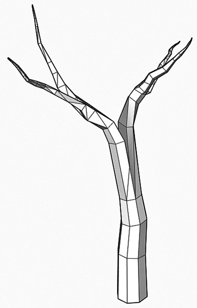
Figure 1.11 – Most of these branches were created using only the Scale and Push/Pull tools
Not a bad-looking tree, but honestly, a little bit light, as far as branches go. Fortunately, we can multiply the number of branches quickly! What we can do is grab a portion of the original model and copy it. Let’s give it a try.
- Use the Select tool to select the top two-thirds of the tree.
- Use Move with the Copy modifier to move a copy of the selection off to the side. Make sure to move it far enough that none of the copied geometry crosses the original.
- Right-click on the selected copied geometry and choose Make Group from the context menu.
- Now, select the Move tool and use the Rotate handles on the group to tilt and spin the group. The goal here is to put this set of branches in a different orientation than the original.
- Now, move this group so that the base overlaps the original geometry.
At this point, you should end up with something like this:
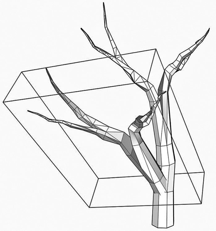
Figure 1.12 – Your tree should look similar, but different
From here, you can continue to use these same steps to copy and group sections of the tree to make more and more branches. You may want to do a little scaling here and there to mix up the size of the branches. Another option is to double-click to edit the groups and use Move and Rotate on the geometry to add even more variation!
In the end, you will have a twisting, turning shape created with only native tools. Note that we did start with an octagon, just to keep the model as light as possible, but you could start your tree with a shape with more sides. For that matter, you could, if you wanted, draw a totally original shape to start your trunk.
One of my personal favorite things about SketchUp is that it is simply a tool for drawing shapes. Great SketchUp modelers can model almost anything using these basic tools. Remember, it is you, the designer, that makes amazing models. The software you use is just the tool to help you realize your creation. Another basic tool that can do far more than users give it credit for is the Follow Me tool. In the next section, we will spend some time learning how to push Follow Me beyond its basic functionality.
Diving deep into Follow Me
Another command that people only scratch the surface of when they learn SketchUp is Follow Me. Generally, we see how Follow Me can be used to put crown molding in a room or can be used with a circle to make a bottle or pawn chess piece. Follow Me is made to extrude faces along paths, so these sorts of things are a perfect use of the tool.
Seems simple enough, right? There are, however, a handful of tips that will move Follow Me from a command you use in a few specific instances to a tool that you will keep on hand for daily use! In this section, you will see how Follow Me can become your go-to tool for creating fillets, rounding over corners, or even generating geometry quicker than any other SketchUp tool.
Follow Me and groups
The first thing to think about with Follow Me is how you set up your initial geometry. Something that many people don’t think about is using a group to separate the Follow Me geometry from base geometry or preselecting paths. Let’s create an example:
- Draw a large rectangle on the ground.
- Push/Pull the rectangle up so you create a box.
- Now use the Line and Arc tools to create a quarter circle in the middle of one of the sides of the top of the rectangle, as shown in this figure:
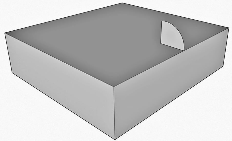
Figure 1.13 – Ready for Follow Me
- Select the Follow Me tool.
- Select the face you created with the Line and Arc tool.
- Move your mouse along the top edge of the rectangle.
Now, unless you are very steady-handed, there is a chance that your cursor may wander just a bit off the line as you move it around the model. When you do this, the profile you are pulling may jump all over the place, creating a crazy extrusion. Sometimes, it will jump down a side of the rectangle; other times, the profile will disappear completely.
Many first-time, self-taught users think that this is the way to use this tool, but there is a better way. The key to a quick and easy Follow Me is to preselect your path!
- Use Select with the Shift modifier key to select the top edge of the rectangle.
- Choose the Follow Me tool.
- Select the same face as last time.
Boom! With that, we have a nice, curved arc that follows the top of the rectangle!
However, if you select any portion of the new geometry, you will see that it is connected to the rectangle. Now, in many instances, there may be nothing wrong with this, as you may want a rim or surface detail to merge with the part geometry. In the case of something such as a chair rail or baseboard, you may want to keep them separate so you can edit them easier in the future or use a different material for them. Let’s redo that Follow Me command with one change.
- Use the Undo command to undo Follow Me.
- Double-click on our arced face (double-clicking will select the face and all the edges that define it).
- Right-click on the face and choose Make Group from the context menu.
- Now, use Select to select the edges around the top of the rectangle. Your selection should look like this:
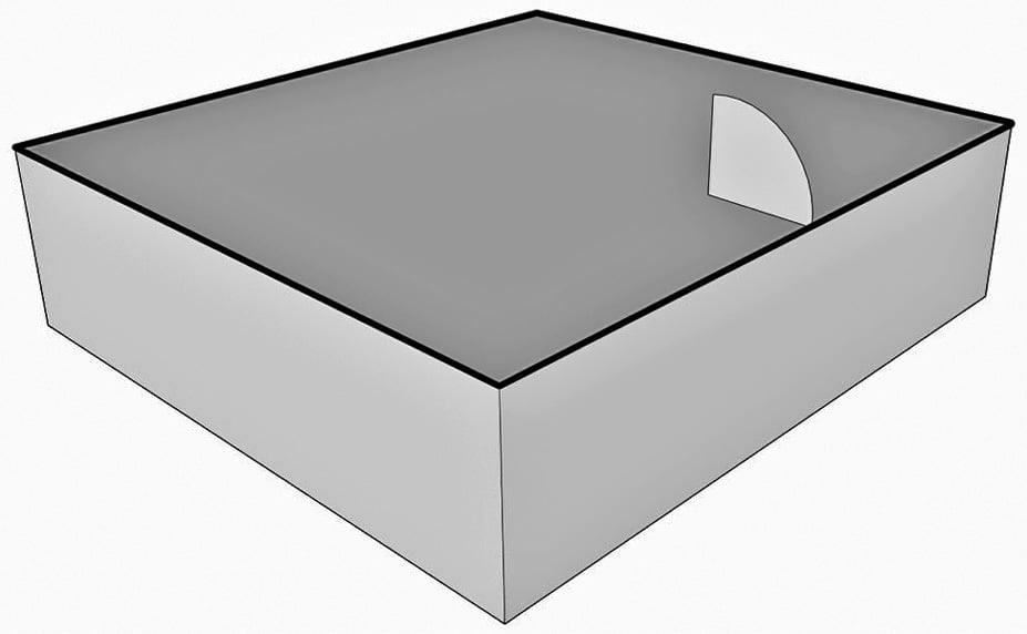
Figure 1.14 – Pre-selected Follow Me path
- Choose the Follow Me command.
The next step is to choose the face that should be used for Follow Me, but if you hover over the group that you created, you will notice that it is not a valid selection. At this point, we need to get inside the group temporarily to select the face.
- Right-click on the group and choose Edit Group from the context menu.
- Select the face.
- Use Select to click outside of the current group.
Notice that if you select the geometry that Follow Me created, it is in its own group. This means you can apply a different tag to this group than the base geometry or easily select all the geometry to apply a specific material. Having it in a separate group makes it much easier to work with!
One of the issues that many users run into with Follow Me is problems with the ends of the extrusion. Remember, when you create a face to be used in Follow Me, it should be perpendicular to the path. Let’s take a look at two examples, as follows:
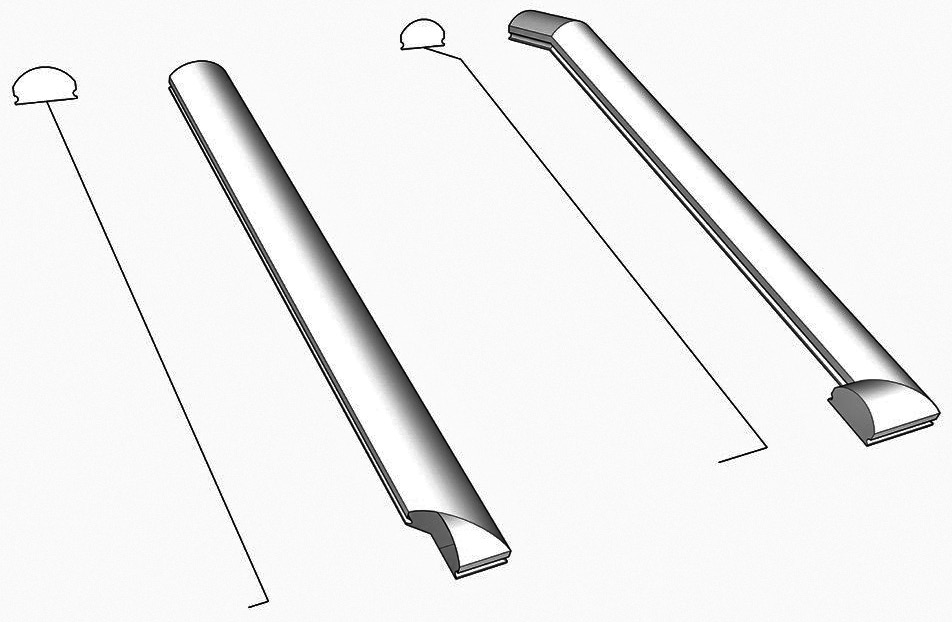
Figure 1.15 – These two examples show the face and path before and after Follow Me
In these examples, a simple profile was created for a handrail. In the example on the left, the profile is not perpendicular to the path and ends up squashed in the final extrusion. To make things worse, the end looks odd because the path is shorter than it should be.
In the example on the right, the path was extended out at both ends, and the profile was placed perpendicular to the end of the path. There may be cases like this where you may want to add geometry to the path or have your extrusion run long of where they will be in your final model. Remember, if you group the face, then the geometry will be easy to trim back after you have created a good-looking extrusion.
Let’s see another example of this with a half-torus. In this example, we will make two shapes and see how important it is to spend a little extra time on your path before using Follow Me. Start a new model and follow these steps:
- Draw a large circle on the ground with its center at the origin.
- Draw a line along the green access from one edge of the circle to the other, cutting the circle in half.
- Erase half of the circle and the line through the middle.
This gives you a perfect half-circle, right? In some cases, this would be a perfect half-circle, but for Follow Me, it might not be ideal. Let’s add another circle to this example and see what happens when we try to create a half-torus.
- Use the Circle command and the Left Arrow key to draw a circle at one end of the half-circle path.
- Put the circle in its own group.
- Run Follow Me with the half-circle as the path and the grouped circle as the face:
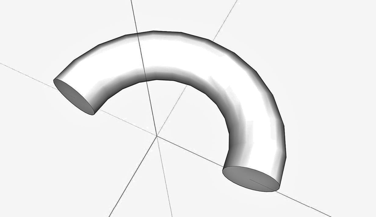
Figure 1.16 – This process did not create a perfect half-torus
Look at the geometry that has been created. Specifically, look at the ends. What is important to notice is how the faces of the extrusion are tilted out from the green axis. Also, while the shapes at the end may seem like perfect circles, check their dimensions using the Tape Measure. If you measure the end vertically and then horizontally you will find that they are not the same.
The issue with this Follow Me is that the shapes were not perpendicular to the ends of the paths, so Follow Me pushed the shape along the path at a little bit of an angle. Let’s try this again with one small change. Just so we don’t forget what this practice produced, group-select the whole thing and then move it off to the side.
Look at the circle. See how the axis hits the circle where two edges meet. What we want to do is rotate the circle just a little bit so that the green axis crosses the circle in the middle of an edge, rather than at an endpoint.
- Select the Rotate command.
- Use the origin as the center of rotation.
- Use the center of an edge as the start point for the rotation.
- Use the green axis as the second point.
- Draw a line across the circle like last time.
- Erase the bottom half of the circle and the line on the green axis.
Look at the edges of the circle you have created. The difference is subtle but important. We will see a big difference when we perform the same Follow Me steps with this geometry as a path.
- Use the Circle command and the Left Arrow key to draw a circle at one end of the half-circle path.
- Put the circle in its own group.
- Run Follow Me with the half-circle as the path and the grouped circle as the face:
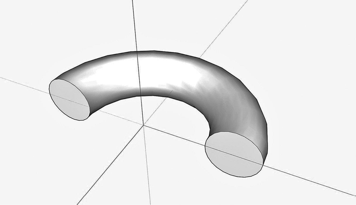
Figure 1.17 – The perfect half-torus
Look at this extrusion compared to the previous effort. The ends line up with the green axis and if you measure the ends, they are still perfect circles! Remember this example next time you use Follow Me and you will avoid issues with the extrusion coming up short or having weird end shapes!
Turning shapes with Follow Me
As mentioned before, Follow Me is often used to make shapes similar to a woodworker turning a piece of wood on a lathe. A profile is aligned with the center of a circle and Follow Me makes a shape based on the profile spinning around the circle. A few examples of this are shown here:
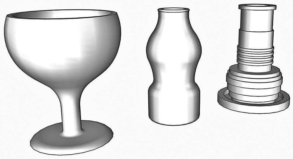
Image 1.18 – Turned shapes using Follow Me
Since the intention of this book is to introduce intermediate concepts and push you past the basic use of the SketchUp toolset, let’s consider a slightly different way to use this setup. Aligning a profile with the center of a shape to follow is a great concept and can be used to quickly create some great shapes, but people often don’t consider that the shape that is being followed does not have to be a circle. Let’s start a new file and model a fancy pedestal in just a few steps:
- Draw a square centered at the origin (use the Toggle Select Center modifier to start a rectangle on origin (Ctrl on Windows or Option on macOS) and watch for the dotted line to indicate square geometry).
While it is not strictly required that you do a Follow Me like this at the origin, it does make it easier on you. By centering the path geometry on the origin, you have a visual indicator of the center of the spin of the geometry.
The next step will be to create the profile. I find that the easiest way to do this is to create a working plane that I can draw my shapes onto. As long as one edge of the plane is along the origin, I know that Follow Me will create the properly turned geometry.
- Draw a rectangle on the red axis (Right Arrow) from the origin up from the square on the ground. You should end up with geometry similar to this figure:
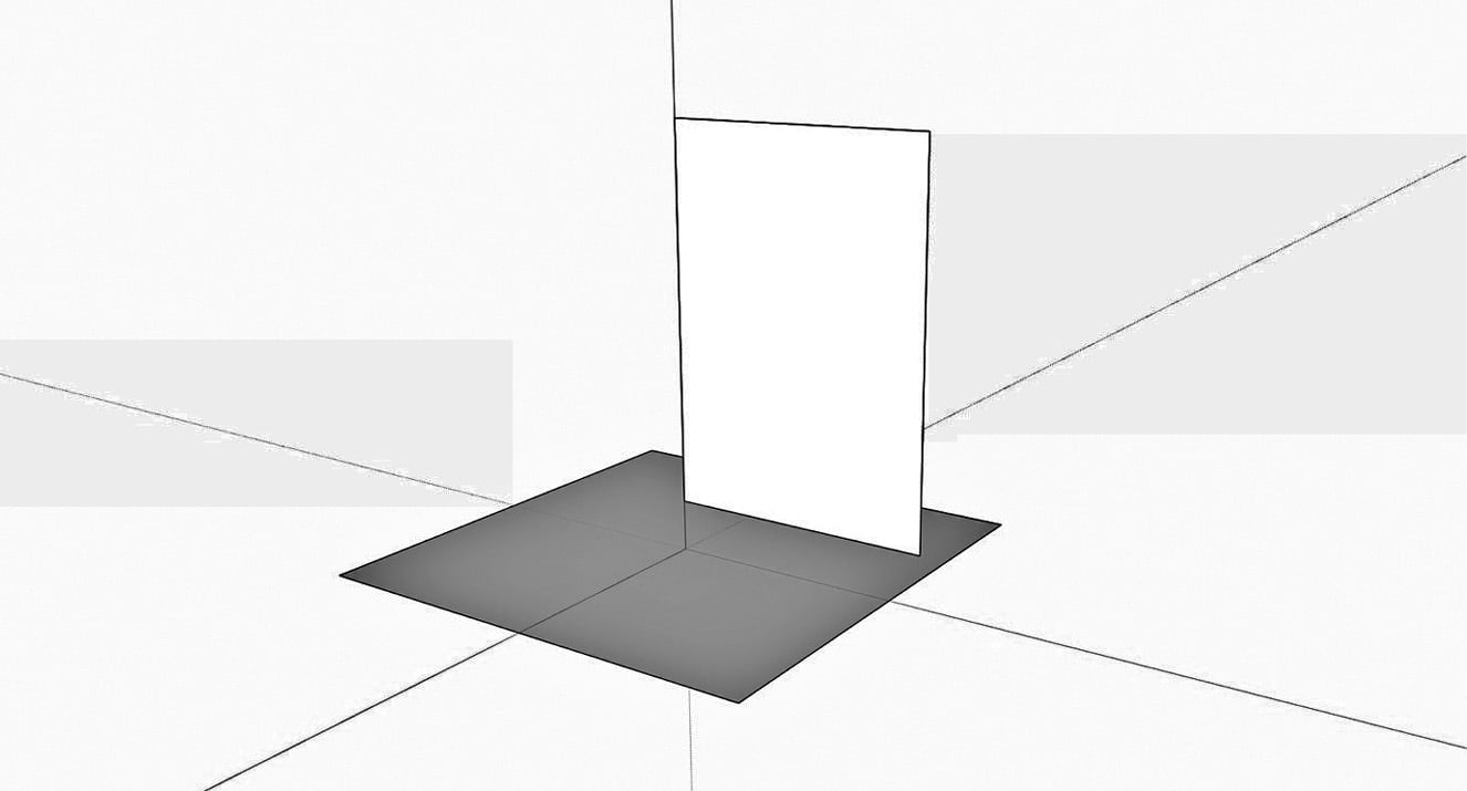
Figure 1.19 – Ready to start creating a profile
- The next step is to create the geometry of the profile. For this example, create something similar to what I have drawn here:
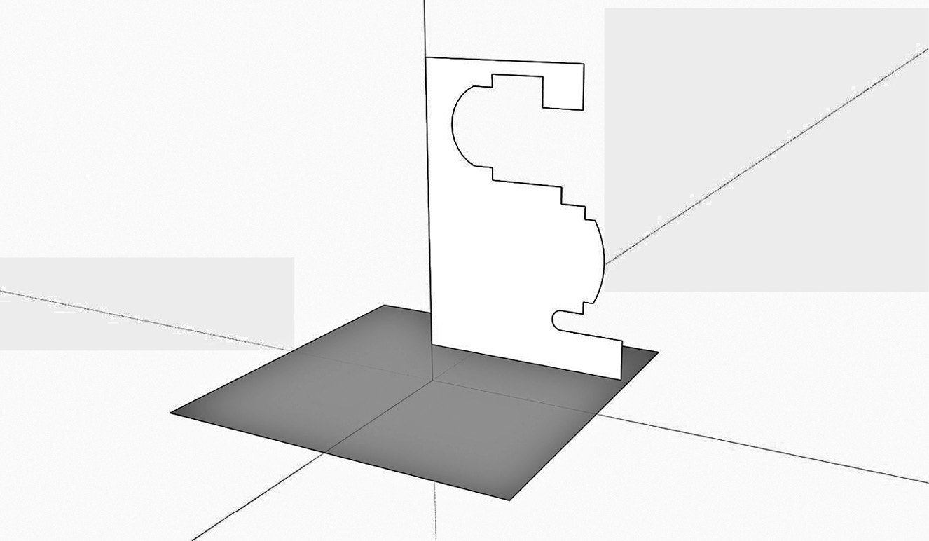
Figure 1.20 – Your profile may vary, but try to create something with a few corners and arcs
- Once you have the profile geometry drawn, erase the extra edges and double-click the profile, then right-click, and choose Make Group from the context menu.
- Select the square (you can choose the edges or simply double-click the face of the square to highlight all of the edges), choose Follow Me, then click the profile:
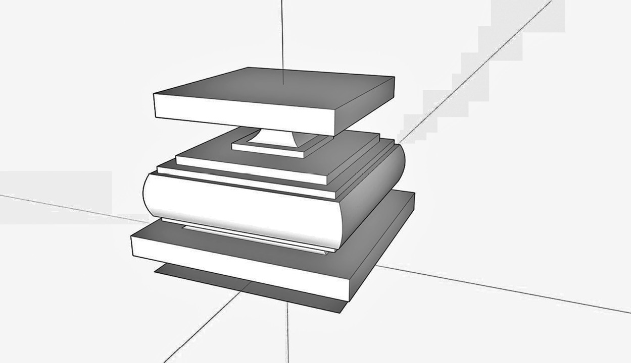
Figure 1.21 – Final geometry
That’s it! Your fancy pedestal is created. Any time you have geometry that follows along a shape, whether it is a linear extrusion similar to what we created in the first example, or if the geometry wraps around an enclosed shape like this pedestal, keep Follow Me in mind as you generate geometry!
Summary
The goal of this chapter was to show you, as a SketchUp user, that the native commands can be pushed beyond their basic functions. You should now have a better understanding of what makes a model, and how you can use native commands in more than just one way.
While this was not a comprehensive list of every way that input or modification commands can be used, it should prompt you to look at the commands in a new way. The hope is that you will now question how these tools function and how you might use the native tools to create geometry beyond how you currently use them. The ability to use the native toolset to its fullest potential will allow you to model quicker and create more detailed geometry without relying on extensions.
In Chapter 2, Organizing Your 3D Model, we will discuss how to use groups, components, tags, and scenes to organize your model, making it easier to work with and move through.