


Advanced Design Methodologies and Strategies
Creating parts and assemblies in Inventor can be achieved in a variety of ways. There are multiple strategies that can be employed and combined to create the desired output; all are valid ways of modeling within Inventor, and each strategy has its own advantages and disadvantages. In this chapter, you will learn the differences between these strategies and how to implement them effectively, across a range of scenarios. You will also learn the advantages of each and how and why each strategy should be applied.
Having practical knowledge of all strategies allows you as a designer to make more informed planning decisions when embarking on the design of a product or project within Inventor. The right application of a strategy to a scenario can bring about significant time savings in terms of the amount of rework or updates required that usually must take place as part of an iterative design activity.
In this chapter, we will cover the following topics:
- Understanding the different design processes
- Creating a multi-body part design
- Creating a layout design from imported
.dwgCAD data - Applying and using adaptive modeling
Understanding the different design processes
Within Inventor, there is a variety of modeling methodologies that can be used and combined. In this section, we will examine each type and how they can be used.
Bottom-up design
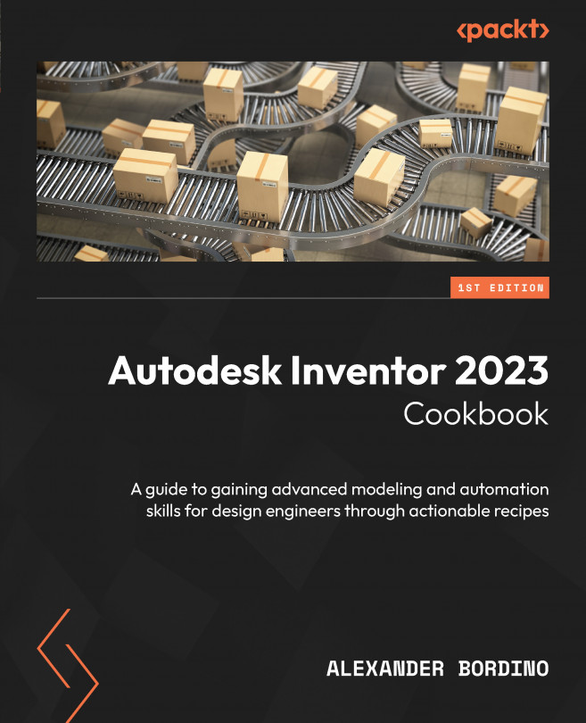
The bottom-up design process is the traditional way of modeling and creating an assembly within a CAD environment. It is a part-centric process, whereby each part’s geometry is created separately in its own independent .ipt part file and then combined into a single top-level assembly .iam file. Independent parts are combined with Mates constraints in the final assembly to create the desired outcome of the final top-level assembly.
The advantages of this methodology are that each part has its own independent file, and therefore its own file structure, which is much easier to understand and organize. Parts can also be updated and changed without influencing related parts in the referenced assembly.
The disadvantages of this structure are that the level of rework can be much higher. Because part files are not linked through geometry, when part A changes in an assembly, the other parts that it may interact with, such as part B or C, will not automatically update. This means that the designer now must spend time manually updating and correcting parts B and C in the assembly to ensure the desired interface and fit between these components is achieved. Depending on the level of change and complexity of the design, this can take a significant amount of time.
Problems can also arise when separate part files are first combined into the assembly. Often, this is due to a lack of engineering information communication, with problems such as misalignment, interference, or an incomplete design.
In Figure 2.1, you can see an example of the structure of a bottom-up design methodology:
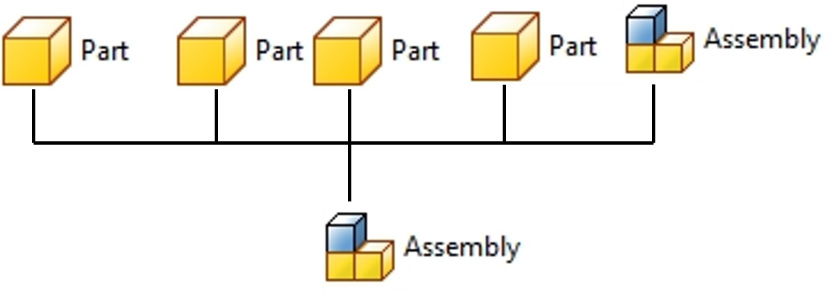
Figure 2.1: Diagram of bottom-up design
Multi-body design
The multi-body design methodology places critical design information within a top-level assembly and communicates this information to lower levels of the product structure.
Multi-body design begins with the creation of a single part or solid as a reference model. Additional solids are then created inside the same part file and exported as parts into an assembly environment. Any changes to this methodology, to the original part, are reflected in the linked parts and assembly, resulting in a true parametric methodology.
The advantages of multi-body design are that all the design resides in a single .ipt file, with the solid bodies extracted later to create parts and an assembly. The reliance on Mates and onstraints in the assembly environment is reduced as parts are created in place and on location.
With this method, there is usually less reworking required as the parametric link between solids from the initial part file is maintained, so as design changes are made, the linked solids also update to reflect the changes, resulting in less rework.
Finally, the body’s visibility can be controlled as a group instead of at an individual feature level, and relationships between bodies can be created and broken freely.
In Figure 2.2, you can see an example of the multi-body design methodology:
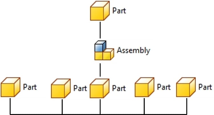
Figure 2.2: Diagram of multi-body design
Layout design
Layout design involves taking an existing arrangement or drawing from a 2D format such as .dwg, importing it into an Inventor sketch environment, and then combining with sketch relationships and feature modeling techniques to derive 3D components from a 2D layout.
The 2D sketch initially contains all the design intent, dimensions, and spatial locations of components within the assembly. Each component is usually broken down into a sketch block, which can be achieved in both Inventor and AutoCAD.
This is widely used in some companies if there is a reliance on the initial design being completed as a 2D layout first, prior to 3D models. It can also be used with other techniques, such as bottom-up or multi-body. An example would be if a supplier of a component could only supply a 2D drawing file, yet the designer required a 3D model to place in the top-level assembly; a 3D variant could be created from the 2D drawing as a reference using the layout design methodology.
With layout design, if the original 2D sketch is updated, these changes are reflected in the 3D model. This means the design can be manipulated from the 2D imported sketch, including the movement and interaction of components.
Figure 2.3 shows the layout design methodology:
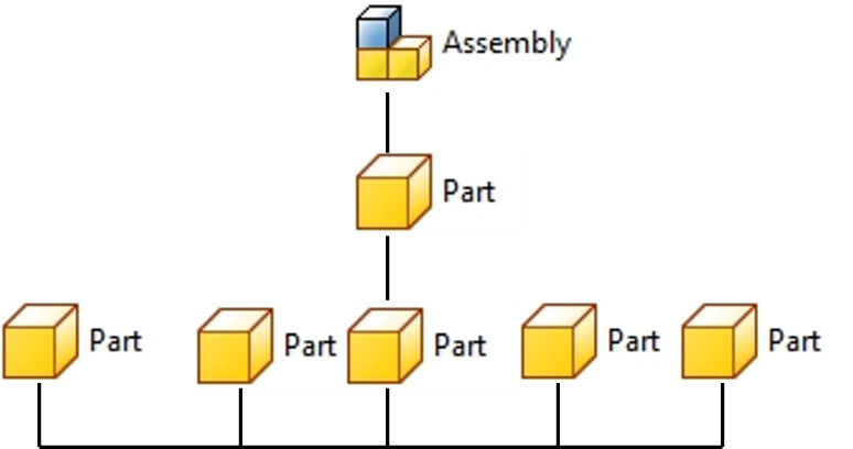
Figure 2.3: Diagram of the layout design process
Adaptive modeling design
Adaptive modeling design uses references from an existing assembly to create parts inside an assembly file, from the projection of existing geometry. Adaptive links are made in this process between sketches and features so that if the parent updates, the child sketch or feature also updates. With an adaptive part, it is intrinsically linked to other parts it shares an adaptive link with.
The advantage of adaptivity is that this link can also be broken if required. It is ideal for determining very specific tolerances in place and on location of where the end part will reside. Because of the adaptive link, the level of rework or updates is further reduced. As parts are created from the assembly environment, the number of mates and constraints needed to position the end components is reduced.
Figure 2.4 shows the adaptive modeling design methodology:
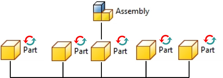
Figure 2.4: Diagram of the adaptive design process
In the next part of the chapter, we will apply this knowledge within Inventor and work with each design methodology.
Creating a multi-body part design
In this recipe, you will create a small subassembly of parts to complete the design of a mountain bike shock absorber. You will learn how to create multiple bodies, in a model, and add features to the bodies. The completed assembly is shown in Figure 2.5, which includes the subcomponent that you will design using the multi-body design process. The rest of the components are supplied as separate solids.
Figure 2.5 shows the completed assembly of the shock absorber containing the part we will create:
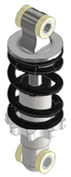
Figure 2.5: Full assembly of the shock absorber part we will create
Getting ready
Start to familiarize yourself with Figure 2.5 as it contains the part we will make (dimensions are not given yet but will be given to you in stages throughout this recipe).
The files that you need for this recipe can be found in the Chapter 2 folder of the Inventor 2023 Cookbook folder.
You can also open Shock_Absorber_Assy.iam as a reference, which can be found in the Chapter 2 folder too (although it is not needed directly for the recipe).
How to do it…
To begin the recipe, we will need to create the first component within the assembly:
- Start the creation of a new part file using the
Standard Metric (mm) .ipttemplate. To do this, select File | New | Metric. ChooseStandard (mm) .iptfor the template, then click Create to complete. - Select Start 2D Sketch and select the XY plane by expanding the Origin folder in the Model Browser.
- From the Sketch tab, in the Create panel, select Circle and create an
18 mmdiameter circle that is centered on the origin, as shown here in Figure 2.6:
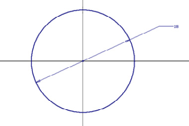
Figure 2.6: The start of the initial sketch
Next, create the rest of the sketch geometry, as shown in Figure 2.7. To do this, draw a construction line from the origin of the circle downward by 21 mm. Next, from the end point, create a horizontal 9 mm line from the construction line end point, then a 3 mm vertical line from the end point of the previous line. This is shown in Figure 2.7:
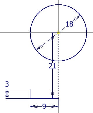
Figure 2.7: The next sketch lines to apply
Ensure the sketch is fully defined before progressing to step 4.
- Next, to create the arc, select the Three-Point Arc command. Start at the end point of the line that is
3 mmin length and snap to the edge of the circle. Set the radius of the arc to15 mm. To fully constrain this arc, you will then need to add a tangent constraint between the arc and the circle, as shown in Figure 2.8:
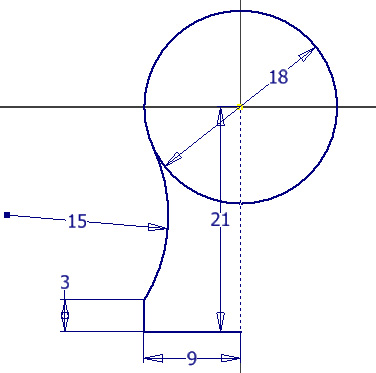
Figure 2.8: 15 mm three-point arc created with a tangency relationship applied between the arc and circle
- As this is a symmetrical shape, we can use the Sketch Mirror command to copy the existing sketch lines about the centerline. This saves time and is the most efficient way to create this sketch. With the Mirror command, mirror all geometry, except the circle, using the center construction line as the mirror line.
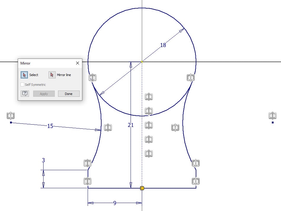
Figure 2.9: The sketch with the mirror applied
- Complete the sketch by selecting Finish Sketch. In the 3D Model tab, select Extrude and select the two closed profiles of the sketch. Enter a value of
14 mmfor Distance A. Then, ensure Direction is set to Symmetric, then select OK.
In this case, with 14 mm set as the overall extrude length, this extends the extrusion both ways by 7 mm in each direction.
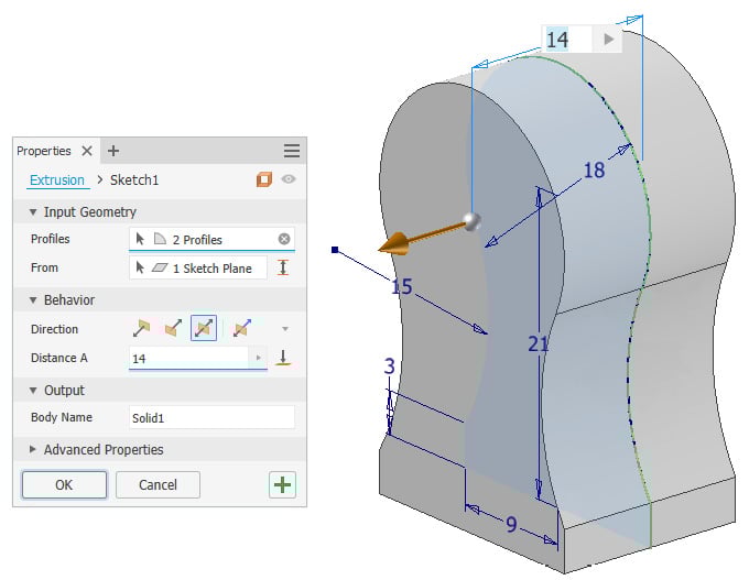
Figure 2.10: Extrusion of the profile applied at 14 mm from the center in both directions
- We will now create additional features on the model as part of the same solid. Select Start 2D Sketch and create a new sketch on the face shown with the following geometry. Select Project Geometry and proceed to select the face of the part, before creating the circles, as per Figure 2.11:
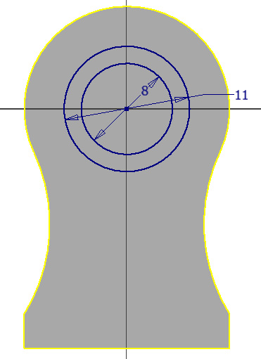
Figure 2.11: The sketch geometry required to create the next features of the part
- Use the Extrude tool on the outer circle to extrude it by
5 mm. - We will now cut the center of the circle. Select Extrude, then Cut, and change Distance A to Through All. Select OK.
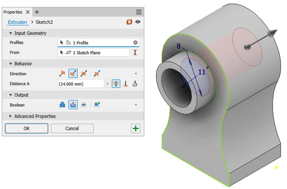
Figure 2.12: The two extrusions created in the same operation
Using the XY plane, in the 3D Model tab, select Mirror and mirror the protruding extrusion from the Model Browser. This replicates the extrusion we created previously, but on the other side of the part.
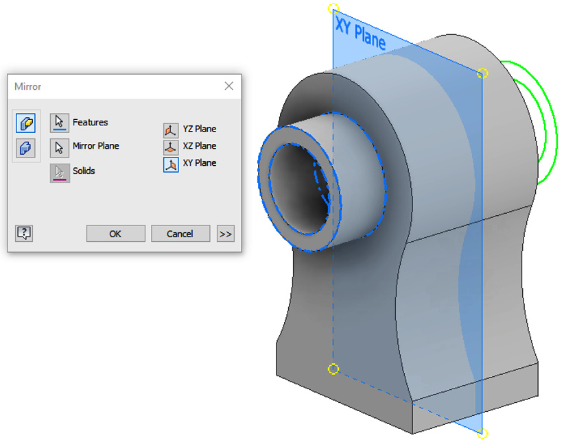
Figure 2.13: Mirror operation in action showing the plane and copied feature geometry
- Select Start 2D Sketch and select the base of the model as the sketch plane. Select Circle and create a
10 mmdiameter circle central to the base of the model. Once complete, select Finish Sketch and then extrude the circle by50 mm, in the direction away from the model. This is shown in Figure 2.14:
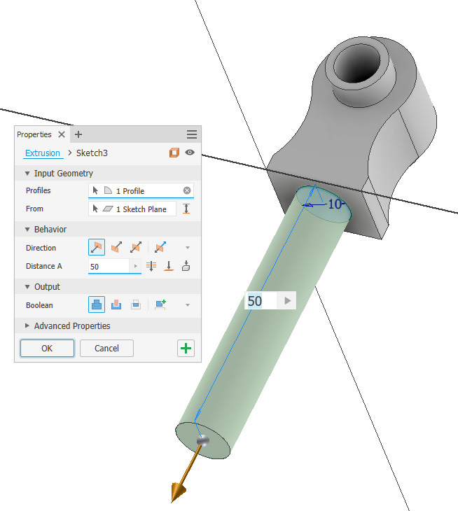
Figure 2.14: 10 mm circle extruded by 50 mm from the base of the part
The first solid body is now complete with additional features added. In the Model Browser, you will see the Solid Bodies folder now shows (1). The additional solids will now be created within the part file.
Figure 2.15: Solid Bodies folder of the Model Browser expanded, showing one solid body in the part file
- Next, select Start 2D Sketch and create a sketch of the face shown in Figure 2.16. The circle must be
18 mmin diameter.
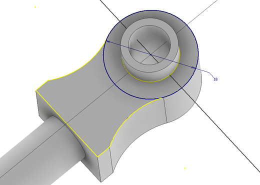
Figure 2.16: Sketch of the circle that must be created, 18 mm in diameter
- This sketch now becomes the basis for the second solid we will create in this part file. Select Extrude and then select the sketch profile created previously in step 11. Set Extrusion Type as To. Select the face of the internal cylinder of Solid1 as the face to extrude toward.
Crucially, at this stage, open the Output area of the Extrude menu and set Boolean as New Solid. This will create the feature as a separate and independent solid from Solid1. Select OK to complete this.
A second solid has now been created.
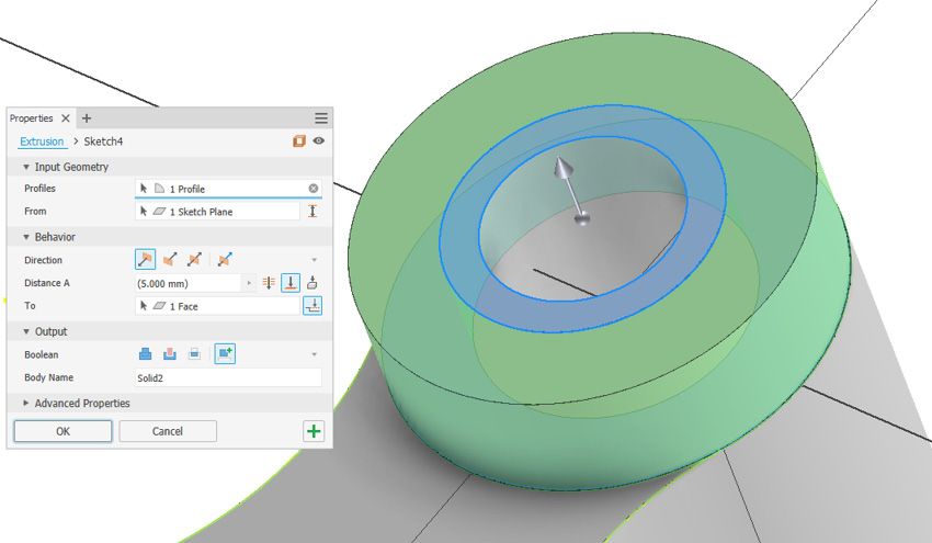
Figure 2.17: Creation of the new solid using the Extrusion command
- As a new solid has now been created, we will begin to modify it. Select Fillet and apply a
.5 mmfillet to the edge of Solid2, as shown here in Figure 2.18. Select OK to close the command.
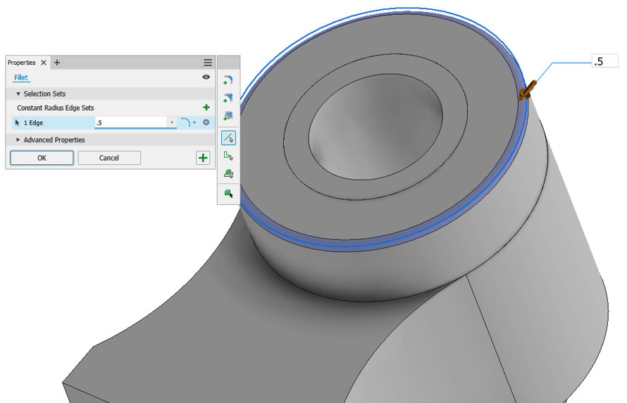
Figure 2.18: .5mm fillet added to the new Solid2 edge
- A final modification we will make to Solid2, independent of Solid1, is a property change. In the Model Browser, expand the Solid Bodies folder, right-click on Solid2, and select Properties.
- In the Body Appearance drop-down list, select Smooth Ivory, followed by OK. We have now independently applied an appearance change to Solid2.
A second instance of Solid2 is required on the other side of Solid1; rather than creating or modeling this again, we can mirror Solid2 along the XY plane to create a second identical instance of Solid2.
- To do this, navigate to the 3D Model panel and find the Pattern commands, and select Mirror. In the Mirror command, rather than using the default Mirror feature, select Mirror Solid. Then, select Solid2 from the Graphics Window. For Plane, use the XY plane. Make sure to also select New Solid in the command as the default will be Join. Select OK to complete. This menu and settings are shown in the top left of the menu in Figure 2.19:
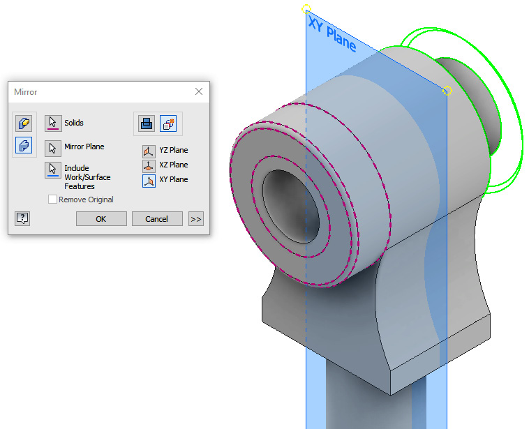
Figure 2.19: Mirror command dialog box showing the settings that need to be applied to mirror Solid2
- Solid3 has been created. The appearance has not transferred from the mirror as this is controlled by the solid properties. In the properties of Solid3, change the appearance of Solid3 to Smooth Ivory (as you did for Solid2 previously).
- To show how all three solids can be edited together, we will now create a small
1 mmhole that goes through all three solids created. Create a new sketch on the face of Solid2, as shown in Figure 2.20. Add a sketch point where the arrow is shown and then exit the sketch.
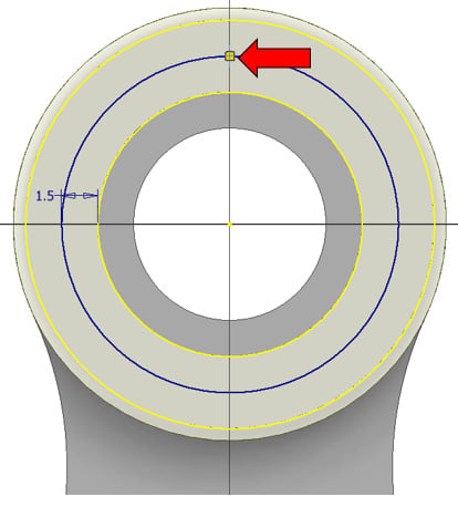
Figure 2.20: Sketch to be created on Solid2 with an arrow indicating the location of the sketch point
- Select the Hole command and pick the sketch point previously placed as the location. Set the Hole type as Simple, the Seat type as None, and the Termination type as Through All with a
1 mmdiameter. In the Solids area, select all three solids to enable the hole to pass through all three independent solids created. This shows how you can perform feature edits in multi-body design, on multiple solids at once if required. Select OK to complete the hole.
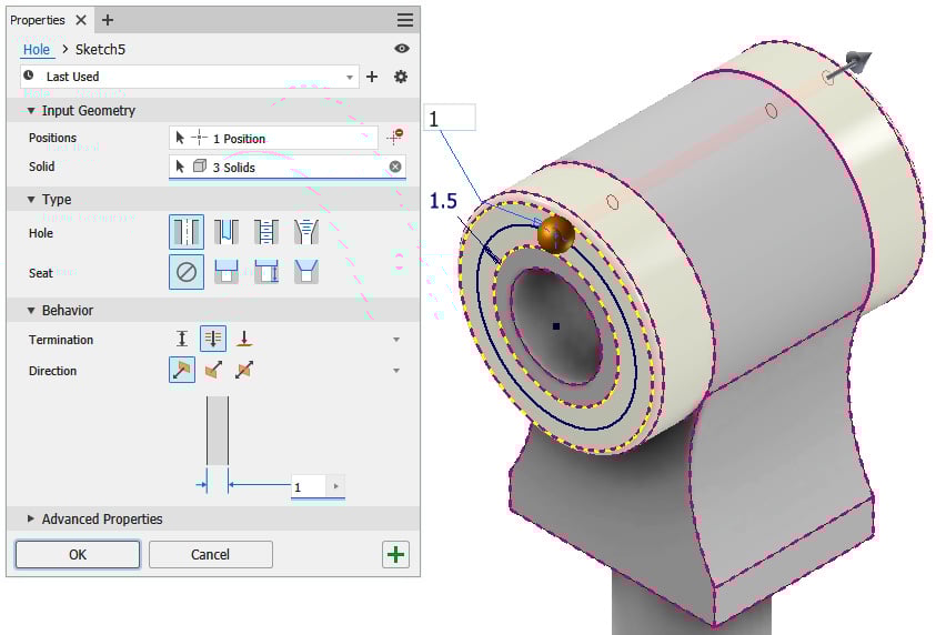
Figure 2.21: Hole command with settings applied in step 19, showing hole going through all three independent solids
- Now, you will extract the solid bodies created to create three independent part files; this is the final stage of multi-body part design. To start, select the Manage tab, then Layout panel. Select Make Components. Inventor will prompt you to save the file. Save the file as
Part1.iptin theShock Absorberfolder, within theChapter2folder. - Select the three solid bodies from the Model Browser to be included in the selection and uncheck Insert components in target assembly (this is not required in this case, but would enable you to also build an assembly of solid body parts at the same time). Then, select Next.
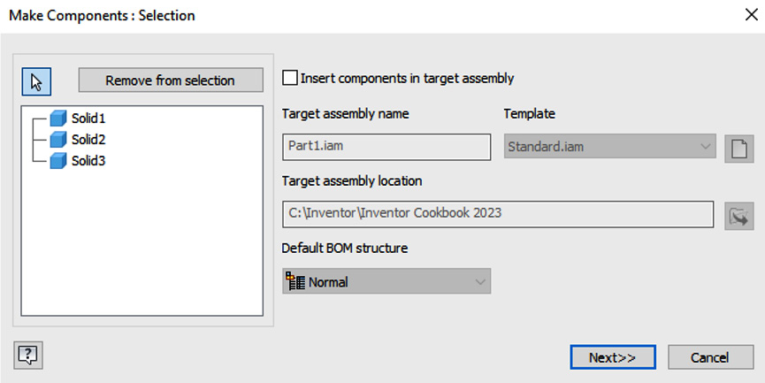
Figure 2.22: Make Components dialog box with the options required
- You can now rename components and choose the template file you want them to use. You can also include any previous parameters and edit the BOM structure.
Select Solid 1 and change the name to SA_MALE_1.ipt. Repeat this for the two other solids, as shown in Figure 2.23, with sequential numbers, in the Component Name column.
Then, select the Page button above the Template column. Navigate to the Metric tab and select the Standard (mm) .ipt template to use. Then, click OK.
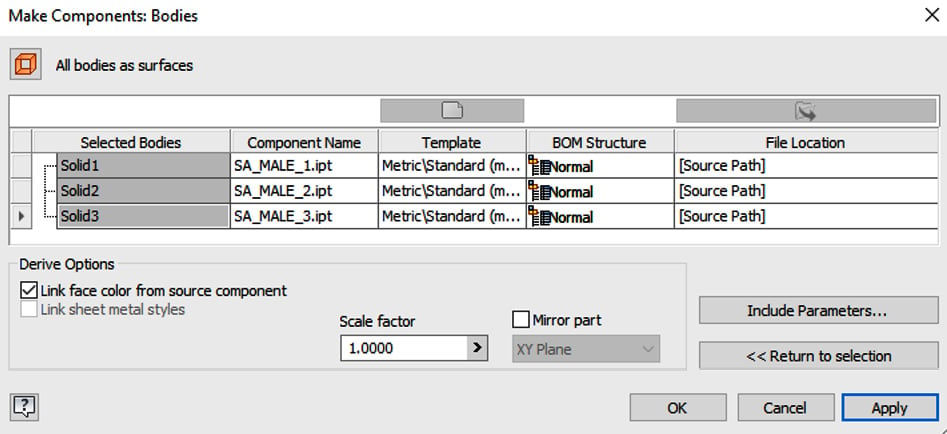
Figure 2.23: Make Components: Bodies dialog box with component names changed and templates redefined
- Inventor will now create the solids as separate
.iptfiles. To review the results, click OPEN and navigate back to theInventor 2023 Cookbookfolder, where the solid parts will be located. This is shown in Figure 2.24:
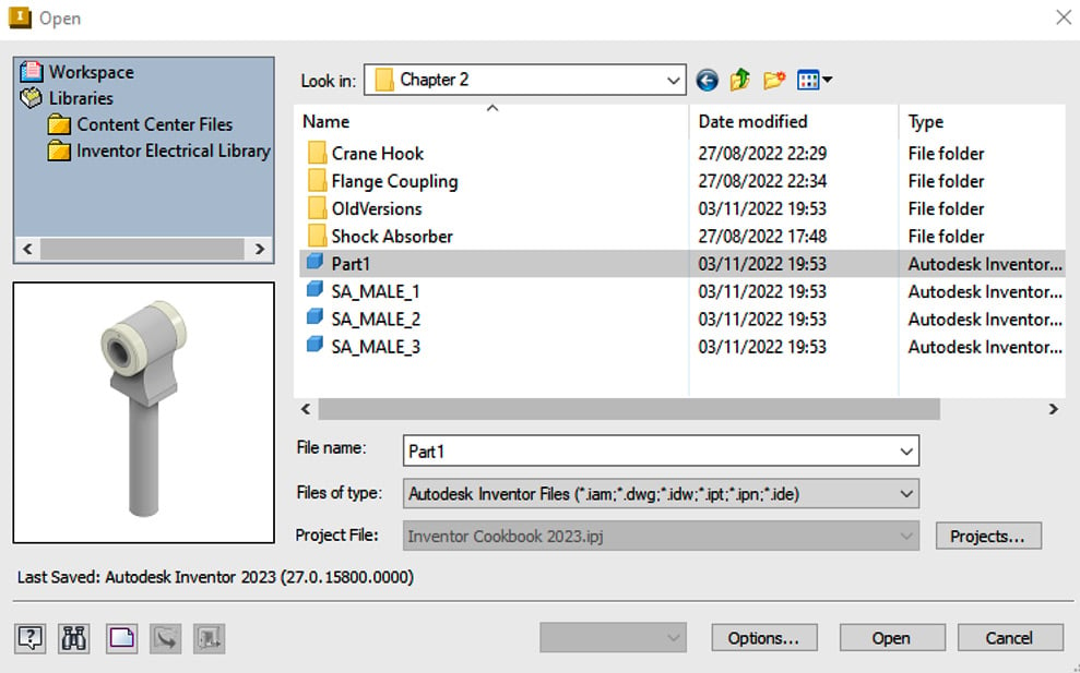
Figure 2.24: Newly created separate .ipt part files from the solids initially created
In this recipe, you have successfully created three independent solids as part of a multi-body design workflow to create a subassembly of parts for a shock absorber. You have then exported each solid as a separate part file. The parent multi-body part file is associative with the exported independent parts, which means that if we change the parent part, the child (exported) parts also change.
Creating a layout design from imported .dwg CAD data
In this recipe, you will create an assembly of part of a crane hook from an existing .dwg file using the top-down methodology of layout design. Any changes made to the sketch will be reflected in the 3D model. The steps to create this are, firstly, to create the layout itself in 2D, import the 2D layout into Inventor, define the sketch blocks, and, finally, make the parts and components using the feature commands in Inventor.
You can see the final assembly of the completed crane hook in Figure 2.25:
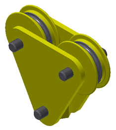
Figure 2.25: The final assembly of the crane hook you will create in this recipe
The original 2D AutoCAD drawing from which this was created is shown in Figure 2.26:
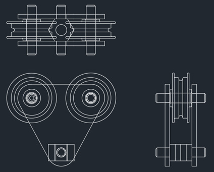
Figure 2.26: The original 2D layout shown in AutoCAD that we will create the 3D assembly from
Getting ready
Navigate to the Chapter 2 folder in Inventor Cookbook 2023 and open the Crane Hook folder. Then, select the 459-25.iam assembly file to look at the completed design in 3D.
The 2D drawing we will create this from can be found in the Crane Hook folder, filename: Crane_Hook.dwg. Figure 2.26 shows the original 2D layout we will use.
To begin, you will need to open a new Metric Standard (mm).ipt file. Have this open and ready before starting the recipe. The original drawing is already drawn to scale 1:1 and does not need dimensional changes when creating the 3D parts; this is simply for reference. The reason for using this methodology is that quite often, at the concept stage, designers create an overall 2D layout in a 2D CAD package, such as AutoCAD, and then require a 3D design for detailed design and manufacturing drawings. This is not the only way to use .dwg files within Inventor.
In this recipe, the original drawing is supplied as a 2D AutoCAD Crane_Hook.dwg file. You do not need AutoCAD to complete this recipe; only Inventor will be used.
How to do it…
To start, we will need to open Inventor and import the original 2D CAD data:
- Create a new
Metric Standard (mm).iptfile. - Then, create a new sketch on the XY plane. This will become the plane to which we will import the existing
.dwg2D drawing of the layout, which will form the basis of the assembly. Because the parts are already drawn to scale and in place, minimal constraining and dimensional input are required, as this has already been completed in the AutoCADCrane_Hook.dwgdrawing file. - With the new sketch active, navigate to the ribbon. In the blank area after Finish Sketch (shown in Figure 2.27), right-click so that a menu pops up. Then, select Show Panels, then Layout, so that a tick is applied. This loads the Layout commands to the ribbon, which will be required for the next steps in this recipe.
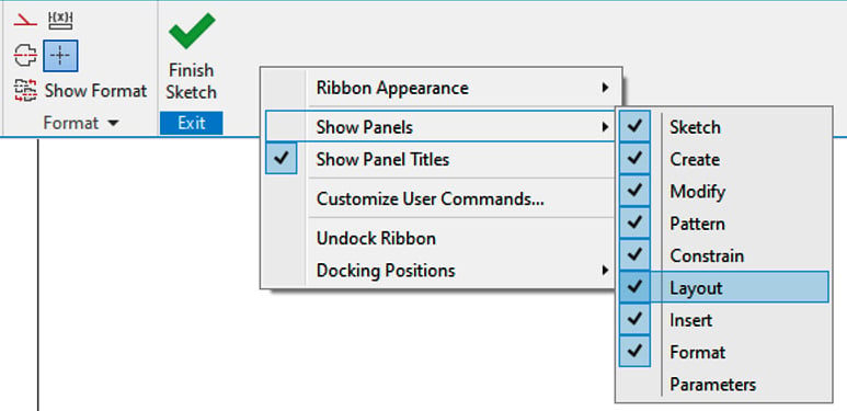
Figure 2.27: Layout panel added to the ribbon
- Next, navigate to the ribbon. In the Insert tab, select the ACAD button.
- You will now import the original 2D AutoCAD drawing into Inventor so that you can use the existing geometry and create the model. Select ACAD, then browse to the
Crane Hookfolder and select theCrane_Hook.dwgfile. Then, click Open.
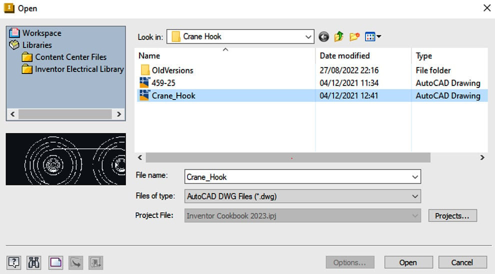
Figure 2.28: Crane_Hook.dwg location shown
- The Layers and Objects Import Options tab has now opened, which allows you to include or exclude certain AutoCAD geometry from the
.dwgfile for import. Untick the All box and click the selection arrow. Then, select the geometry highlighted in Figure 2.28. Now, you can click Finish. This will import only this highlighted geometry from the model. Then, select Next, followed by Finish.
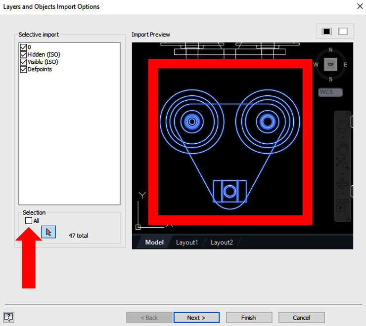
Figure 2.29: Selected geometry we require
Now, the selected geometry will appear in the sketch.
To move the imported geometry to the correct position, we first need to create this as a sketch block. Select Create Block from the recently added Layout tools in the ribbon.
- Select all the geometry that was imported and then select the insertion point (Figure 2.30) as the center of the bottom circle. Click OK to complete the creation of the sketch block. You have now created a sketch block that can be constrained.
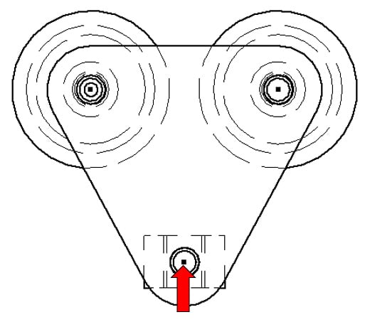
Figure 2.30: Insertion point for the sketch block
- Next, use Coincident Constrain to constrain the center of the insertion point of the sketch block to the origin of the file, then select Finish Sketch.
Figure 2.31 shows the newly created sketch block constrained to the origin:
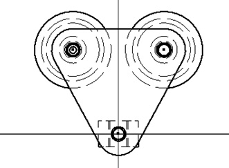
Figure 2.31: Sketch block of imported geometry constrained to origin
- Turn on the visibility of the YZ plane by right-clicking the YZ plane in the Model Browser and selecting Visibility; this turns the visibility of the plane on.
- Select Plane and then select the YZ plane as the first reference. For the second reference, select the center of the top-left circle of the sketch block, as shown in Figure 2.32:
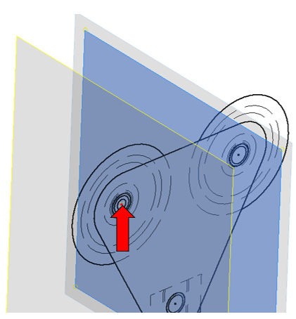
Figure 2.32: Plane creation using the existing YZ plane and reference point on the sketch block
- The newly created Workplane 1 will act as the reference plane for the next sketch and the next piece of imported geometry. Select Start 2D Sketch on Workplane 1.
- Select the ACAD import button and import the
Crane_Hook.dwgfile. This time, select only the geometry shown in Figure 2.33 and click Next followed by Finish to import the geometry into the sketch:
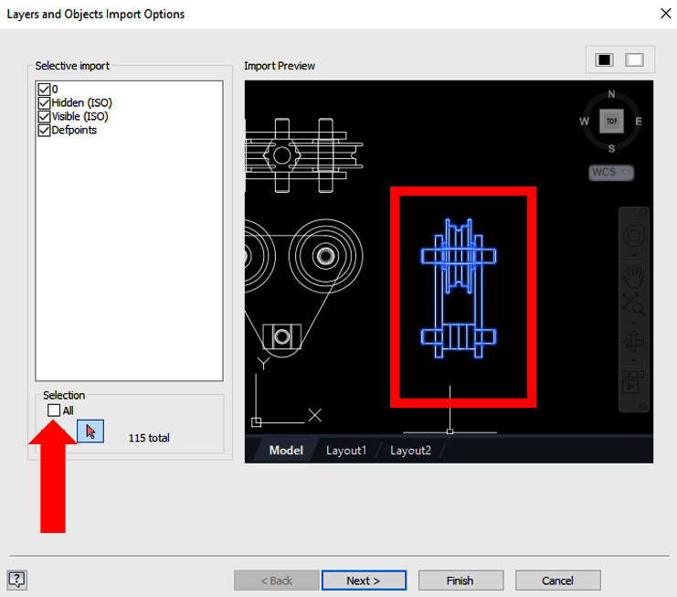
Figure 2.33: The geometry that is required for the second import option
- Create a sketch block of the newly imported geometry with the same process previously shown in steps 7 and 8.
- Upon completion of these two sketch blocks, the Blocks folder in the Model Browser should show two sketch blocks: Block1 and Block2.
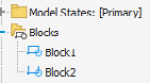
Figure 2.34: Block1 and Block2 in the Model Browser
- Edit Sketch2 from the Model Browser, that contains Block2, select the Sketch tab, and select Rotate from the Modify tools to rotate the sketch block to the orientation shown in Figure 2.35. Ensure your sketch matches that of Figure 2.35:
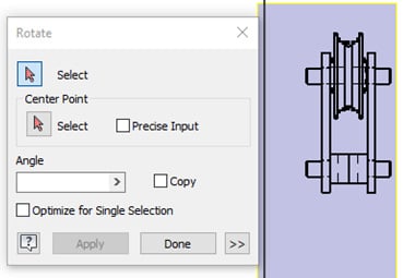
Figure 2.35: Rotate used to rotate the sketch block in sketch mode to the orientation shown
- Save the file as
Crane_Hook_Layout.ipt. - Now that the sketch block has been created and is in the correct orientation, it needs to be constrained in context with the first sketch block that was created. Edit the sketch that contains Block2 that you rotated. Select the Project Geometry command and project the point shown in Figure 2.36:
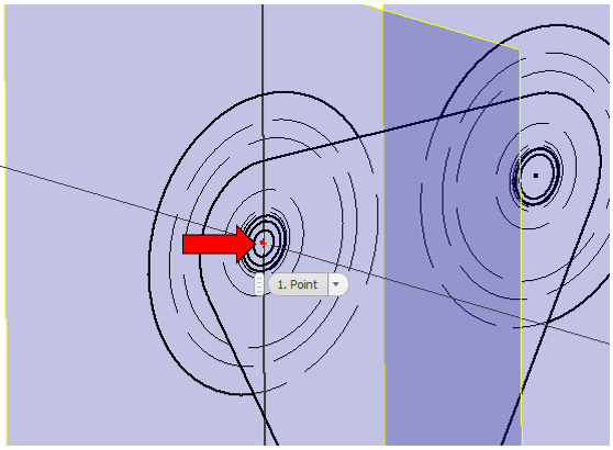
Figure 2.36: Point to project for the second imported sketch
- In the same sketch, select the coincident constraint. Pick the mid-point shown in Figure 2.37 as the first reference:
Figure 2.37: The first reference to select
- For the second reference, select the projected point created in step 17. The sketch block should then be constrained in the position shown in Figure 2.38:
Figure 2.38: Two sketch blocks constrained and in position
Now that the sketch blocks are in position, we will explode them. This is to separate the individual sketch elements so that individual components can be made from them. The reason they were converted to sketch blocks was to enable us to constrain them first to the origin and then to each other in the correct location. Doing this allows us to utilize all aspects of the 2D views of the crane hook provided.
- In Model Bowser, expand the Sketch2 node and right-click on Block2:1, then select Explode. Then, select Finish Sketch from the ribbon.
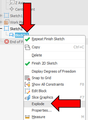
Figure 2.39: Sketch2 expanded and Block2:1 exploded
- In the Model Browser, click on the Block1 name and rename it to
CH_Plate. - Select Edit Sketch for Sketch2. Select Create Block, then select the geometry shown in Figure 2.40. Set the name of the block to
CH_Pulley. Click OK.
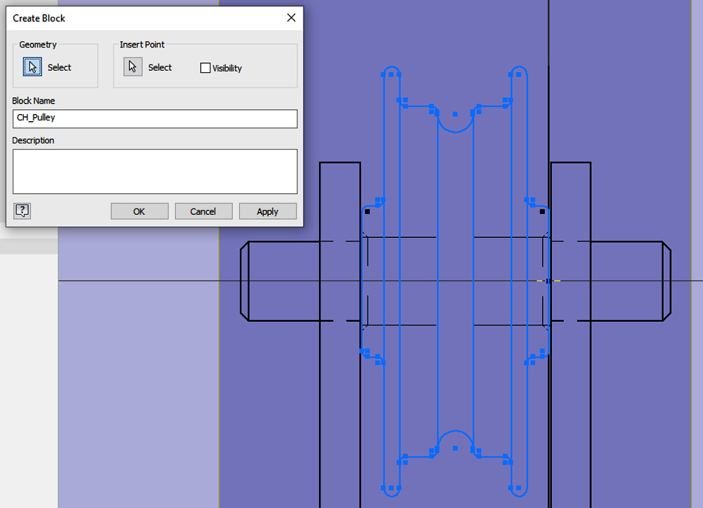
Figure 2.40: CH_Pulley block created
- Create another new sketch block; in this instance, select the geometry shown in Figure 2.41 and set the name as
CH_HookHousing:
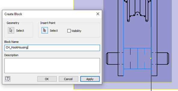
Figure 2.41: CH_HookHousing sketch block created
For the final sketch block for the shaft, edit Sketch2 and draw additional lines with the Line command to complete the geometry. This is shown in Figure 2.42. Do not forget to apply a horizontal line across the centerline of the shaft. This is required for a revolve later.
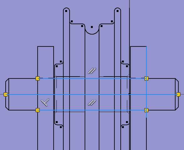
Figure 2.42: Additional two sketch lines created on Sketch2
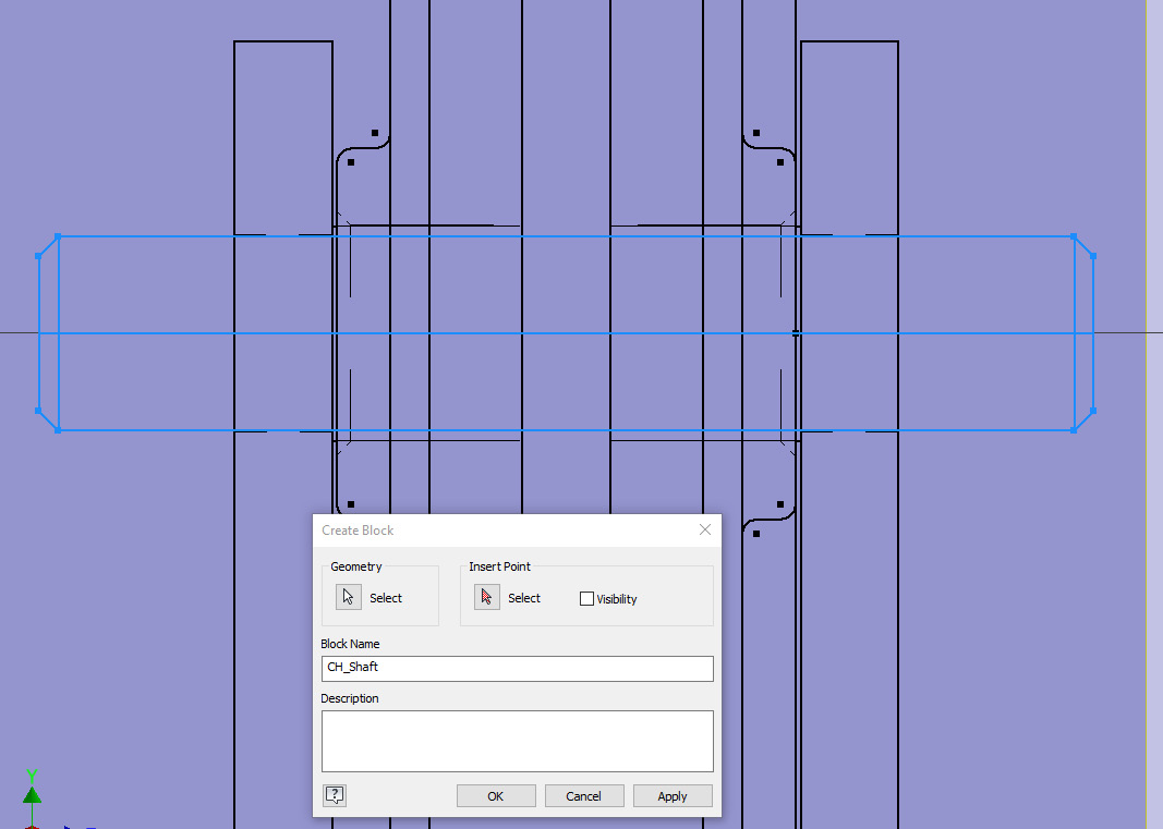
Figure 2.43: Third sketch block to be created from Sketch2
- All sketch blocks required have now been created. These sketch blocks now need to be exported as components. Exit all sketches in the part file and select Make Components from the Manage tab. If you have not saved the file yet, you will be prompted to do so. Save the file in the
Chapter 2|CraneHookfolder. - Expand the Blocks node in the Model Browser and select all created sketch blocks (apart from Block 2) to be created as new components, then select Next.
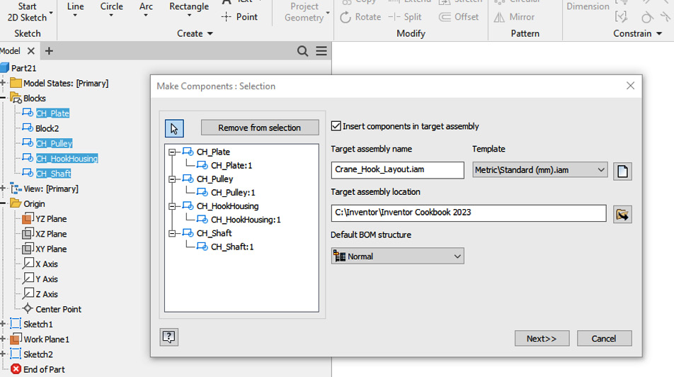
Figure 2.44: Sketch blocks selected in the Make Components dialog box
Note that the target assembly name is the same as the name of the original part file, but with the .iam extension. This is the assembly file Inventor will place the newly created components within. Under Template, select the page icon button. Then, navigate to the Metric tab and select Standard (mm) .iam, as shown in Figure 2.45. Then, select OK. Select Next.
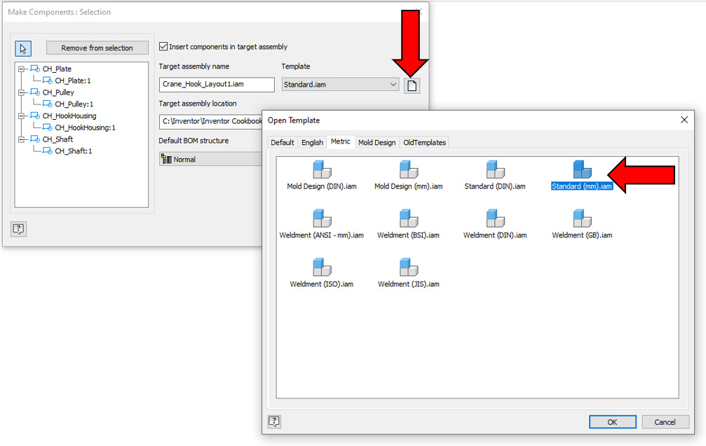
Figure 2.45: Template for the assembly
- Select the first sketch block, CH_Plate, from the list. Select the page icon above Template.
- Then, navigate to the Metric tab and select the
Standard (mm) .ipttemplate for each sketch block, as shown in Figure 2.46:
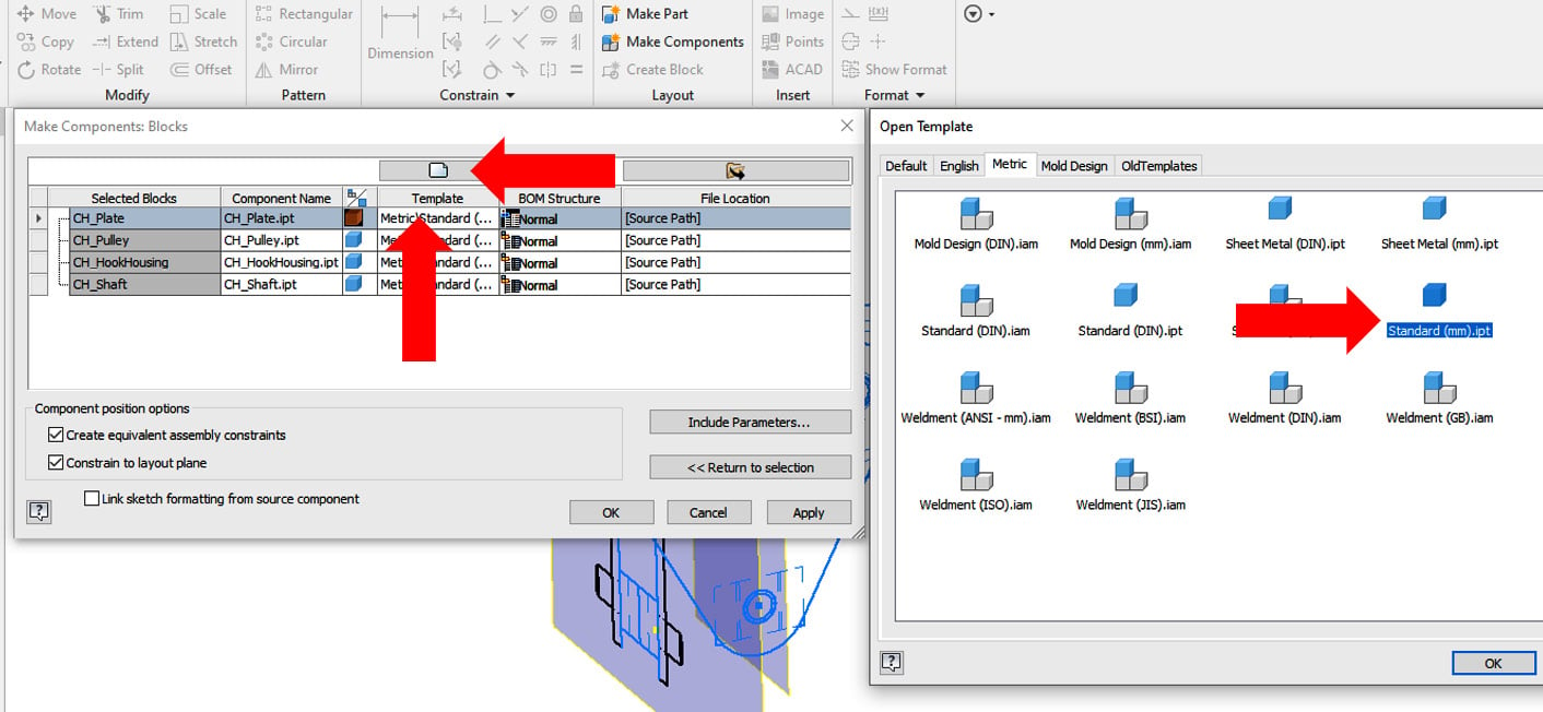
Figure 2.46: Template for the parts
- Repeat steps 27 and 28 for each sketch block in the list, until the list resembles Figure 2.47. Select OK to complete.
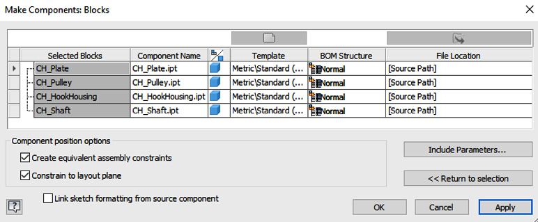
Figure 2.47: Sketch blocks in the Make Components menu, with templates configured to Standard (mm) .ipt
Tip – templates
Many of the manual operations in the selecting of templates in these functions can be automatically set once a part file or assembly file template has been created.
- The newly created components now open in a new assembly
.iamfile namedCrane_Hook_Layout.iam. Note how in the Model Browser, each sketch block has now been created as a component or part within the assembly. The sketch layout geometry is still present in the Graphics Window, and we can now use this to add 3D geometry to the individual components.
Figure 2.48: Sketch blocks converted into parts in an assembly file
- Move the cursor over the CH_Plate component, right-click, then select Edit.
- Select Extrude and pick the profiles of CH_Plate to create the end part. Ensure you do not pick the holes for the shafts. (If you do accidentally fill them in, they can be added later as an Extruded Cut operation.) Leave Direction as the default and set the depth of the extrusion (Distance A) to
31.75 mm. This is shown in Figure 2.49. Then, select OK.
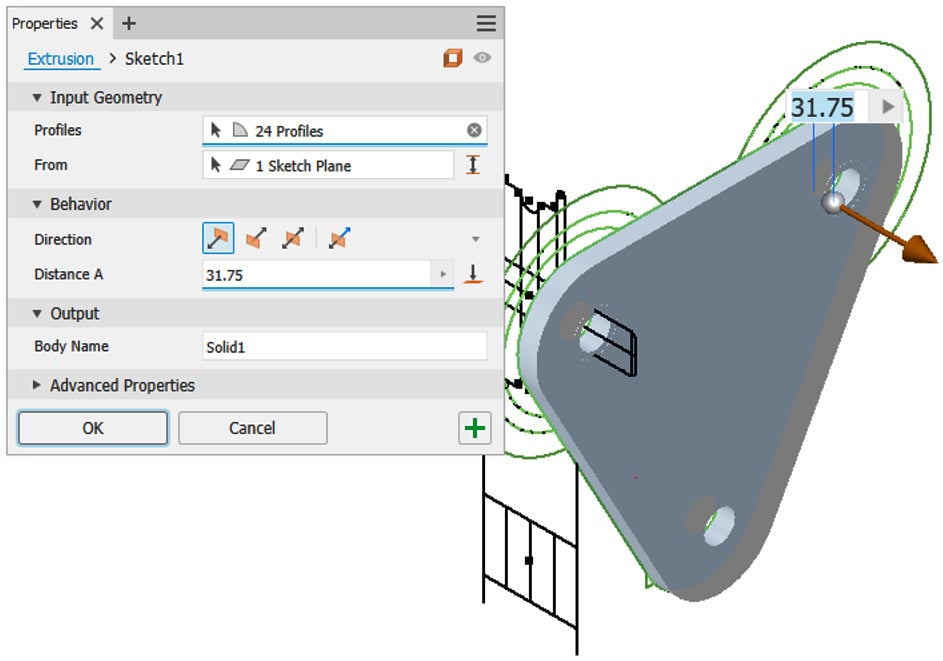
Figure 2.49: Extrusion of CH_Plate using the existing ACAD geometry
- Select Return from the ribbon to return to the assembly and navigate to the other side of the newly created extrusion feature. Under the Plane command, select Offset from Plane and create a new offset plane from the XY plane at the top level of the assembly, which is a distance of
76.2 mmfrom it, as shown in Figure 2.50:
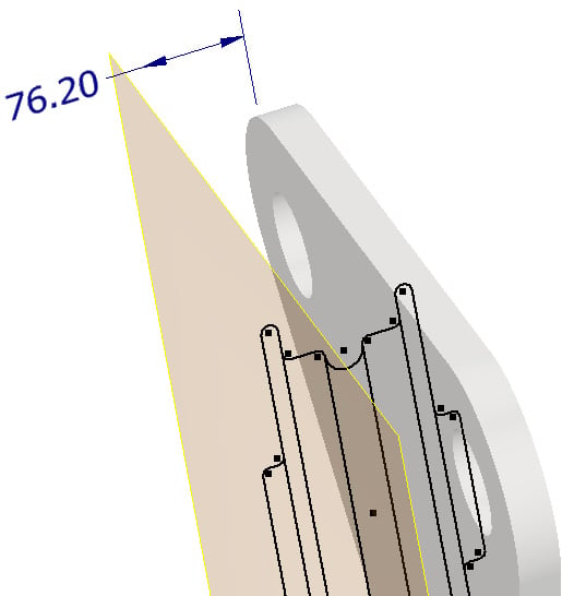
Figure 2.50: The placement of an additional work plane
- In the Assemble tab, select Mirror and mirror the newly extruded CH_Plate component using the recently created Offset Work Plane 1 as the mirror plane.
The correct settings to apply in the Mirror Components menu are shown in Figure 2.51. In the Mirror command, select the green icon to activate Reuse Component.
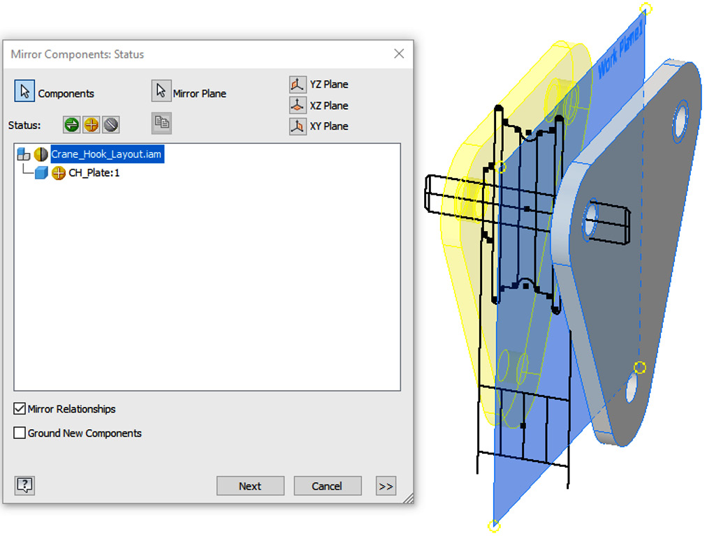
Figure 2.51: Settings applied in the Mirror Component window to apply and the new component in preview
- Select Next and then OK. You have created the first components from the original AutoCAD data that was imported.
- Next, right-click CH_Pulley from the Model Browser and then select Edit. Then, right-click on Sketch1 in the Model Browser and select Edit Sketch on Sketch1. Draw the additional sketch line, as shown in Figure 2.52. This will act as an axis to revolve the new component.
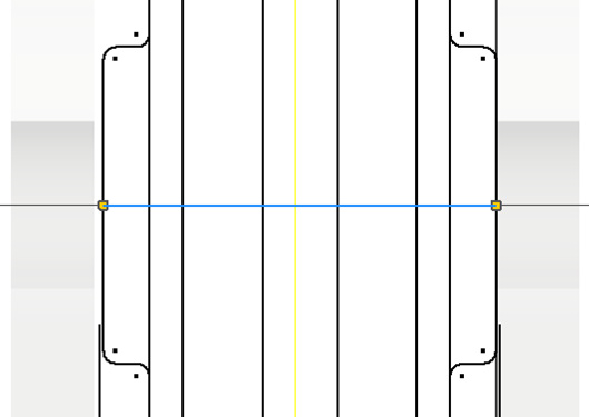
Figure 2.52: Line applied to the sketch to act as an axis for a revolve operation
- Select Finish Sketch and then Revolve from the 3D Model tab.
- Select the geometry shown in Figure 2.53 for the profile, and then pick the axis as the newly created sketch line. Then, hit OK.
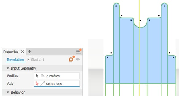
Figure 2.53: Geometry to select in the revolve operation
The resulting feature should resemble Figure 2.54:
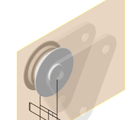
Figure 2.54: Completed revolve operation shown
- Select Start 2D Sketch and select the face shown in Figure 2.55. Proceed to select Project Geometry and select the geometry shown in Figure 2.55 from
CH_Plate. Select Finish Sketch.
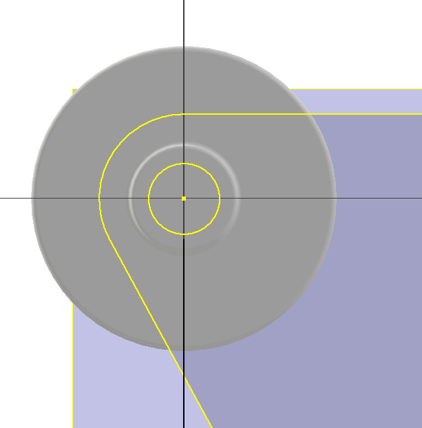
Figure 2.55: Geometry to project
- Select Extrude to create a hole from the circle in Figure 2.55. Figure 2.56 shows the extruded cut and the settings to apply. Select OK to complete.
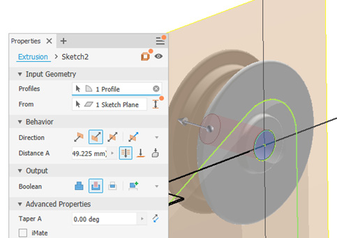
Figure 2.56: Extruded cut deployed on the newly created feature, using projected geometry from CH_Plate
- Hit Return in the ribbon to return to the top level of the assembly after completion.
- The CH_Pulley component must now be mirrored using the same methodology as CH_Plate. To start, navigate to the top level of the assembly and mark the YZ plane as Visible.
- Select Mirror from the Assemble tab and select CH_Pulley as the component and the YZ plane as the mirror plane. Select Reuse for the Status option, as shown in Figure 2.7:
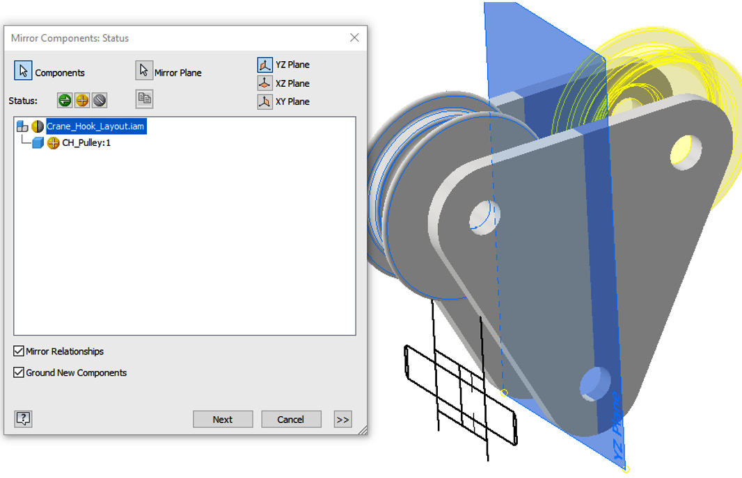
Figure 2.57: Mirror Components menu with a preview of the new CH_Pulley instance
- Complete the operation by clicking Next, then OK.
- For the crane housing component, the imported geometry is not in the correct place, but we can still utilize it. Edit CH_HookHousing and in the Model Browser, expand the Origin folder under CH_HookHousing. Select Start 2D Sketch on the XY plane of CH_HookHousing.
- Select Project Geometry and project the lines shown in Figure 2.58. If you cannot project the lines, you can also draw a rectangle over the top; it should snap to the end points, so you know the geometry is correct. The result should be a sketch that is a rectangle.
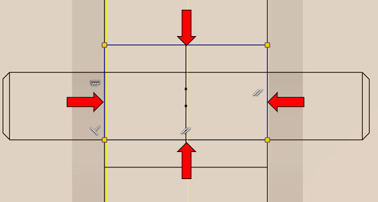
Figure 2.58: Projected lines
- Select Finish Sketch and then click Extrude. Pick the profiles shown in Figure 2.59 and extrude a distance of
500 mm; this will become CH_HookHousing.
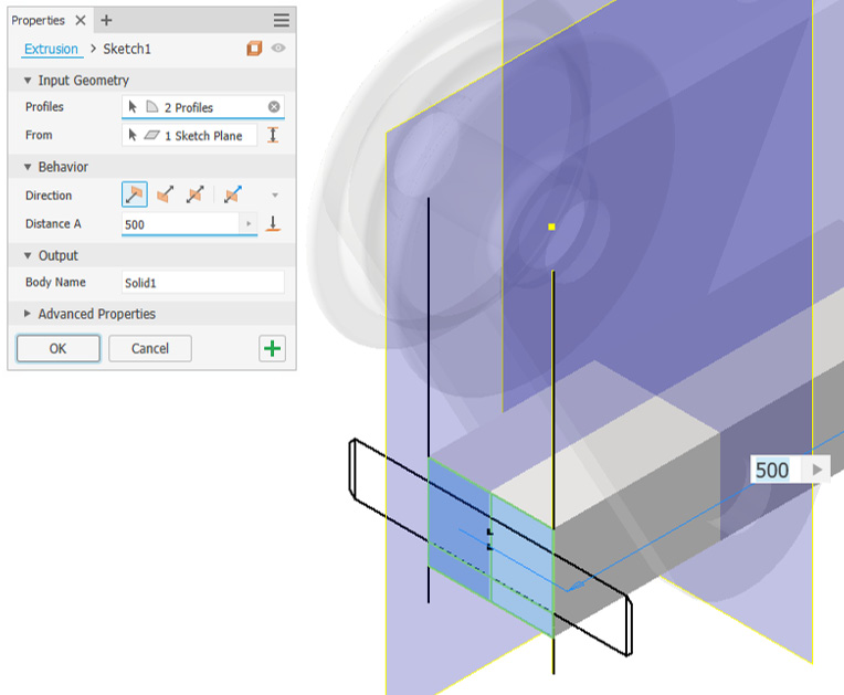
Figure 2.59: 500 mm extrusion to perform
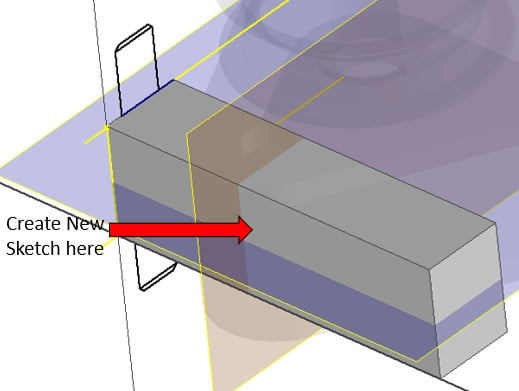
Figure 2.60: Location to start a 2D sketch
Select Project Geometry and select the face of the extrusion and the YZ work plane of the assembly file. Select the Rectangle command dropdown and select sketch Polygon. Create a six-sided polygon at the intersection, shown in Figure 2.61. Then, apply a horizontal constraint to the top line of the polygon to straighten it.
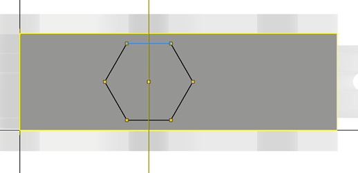
Figure 2.61: Projected sketch lines and polygon
- To constrain the polygon to the correct size, add the following dimensions to the sketched polygon shown in Figure 2.62. Then, sketch a circle from the center point of the polygon with a diameter of
77 mm.
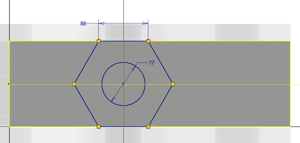
Figure 2.62: Dimensions required and additional sketched circle
- Select Finish Sketch.
- Select Extrude. Then, select Intersect for the Boolean option.
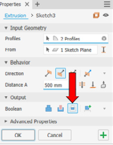
Figure 2.63: Intersect selected in Extrude
Select the two profiles of the polygon, as shown in Figure 2.64, with the Through All option selected. This will maintain the polygon shape and remove all excess material.
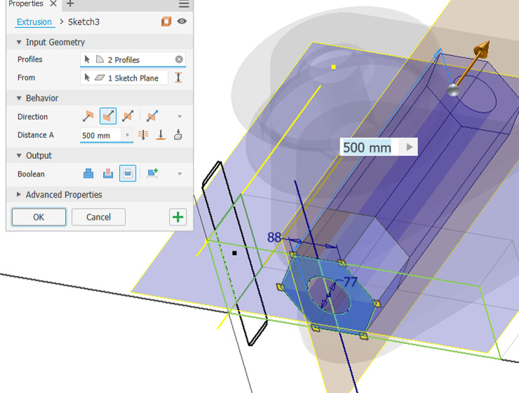
Figure 2.64: Extrude menu shown with profiles selected for the intersect operation
- Complete the operation with OK.
- Select Start 2D Sketch, on the face shown in Figure 2.65, then select Project Geometry of CH_Plates Hole and select Extrude as a Cut, selecting Through All. CH_HookHousing is now complete.
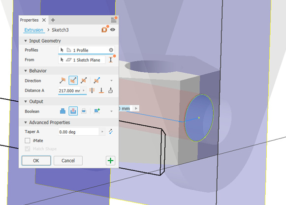
Figure 2.65: Extruded cut menu shown with profiles selected
- Return to the top level of the assembly. The final stage is to create the CH_Shaft component from the original 2D layout.
- Navigate to the the Model Browser, right-click Crane_Hook_Layout1, and select Visibility to turn the original layout on.
- Move the cursor over the CH_Shaft component in the Model Browser and select Edit.
- Select Revolve, then select the profile shown in Figure 2.66. For the axis, select the centerline of the sketch. The preview should resemble Figure 2.66. Select OK to complete the revolve operation.
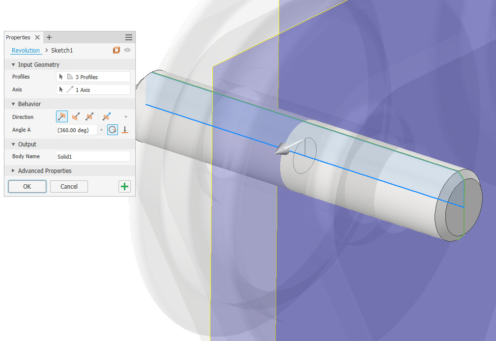
Figure 2.66: Revolve to complete the CH_Shaft component
- Select Return to go back to the top-level assembly.
- All components have now been created from the initial layout design. The only remaining task is to mirror or copy CH_Shaft to the other two locations.
- Optional: Select the Copy command and assembly constraints to create the final instance of CH_Shaft. The final assembly should resemble Figure 2.67.
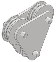
Figure 2.67: Completed assembly of the crane hook with three instances of CH_Shaft applied
You have successfully imported and used an existing 2D AutoCAD sketch to create 3D geometry in Inventor as part of a layout design workflow.
Applying and using adaptive modeling
Adaptive modeling involves creating parts within the context of an assembly. An initial part is created and then placed and grounded within an assembly file. Other parts are created in place from the original part in the assembly file.
In this recipe, you will take an imported flange coupling assembly and create a mating plate and gasket that are adaptively linked. This means that as changes are made in one component, they will automatically be reflected in the linked components, without manual design changes. This is known as an adaptive link.
Getting ready
In the Chapter 2 folder, select the Flange Coupling folder. Then, open Flange Coupling.iam.
How to do it…
To begin, we will open the existing assembly. Then, we will create new components within the context of it:
- With the
Flange Coupling.iamassembly open, navigate to the top left of the screen, to the Assemble tab, and select Create. The menu shown in Figure 2.68 will appear. - Enter
Gasketfor New Component Name and set Template to Metric\ Standard (mm).ipt. Ensure New File Location is set toC:\Inventor\Inventor Cookbook 2023\Chapter2\Flange Coupling\.
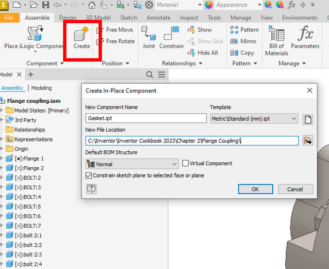
Figure 2.68: Create button in the ribbon, with the Create In-Place Component window active
- Select OK. Inventor then prompts you to pick a face or plane to build the new component. Select the face highlighted in Figure 2.69:
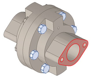
Figure 2.69: Face selected
- The model will now turn transparent. Select Start 2D Sketch and pick the same face previously selected, in step 3.
- In the new sketch, select the Project Geometry command, and then select the face shown in Figure 2.70 to project all the edges shown:
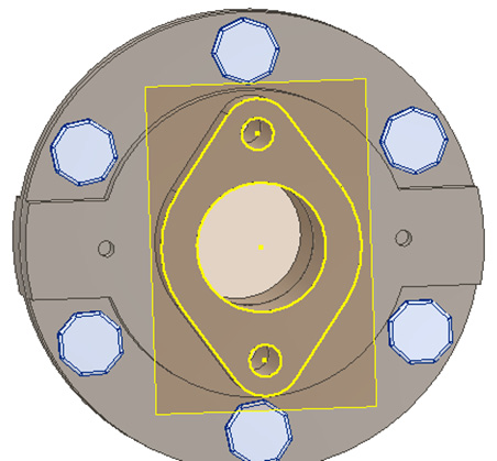
Figure 2.70: Projected geometry shown
- Select the Extrude command and select the profile previously created in step 5. Extrude the gasket by
1.5 mmand select OK.
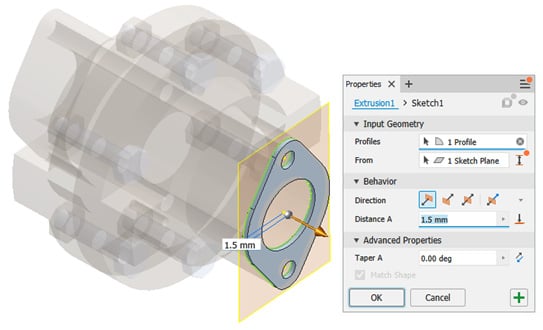
Figure 2.71: Extrusion of previously created projected geometry
- Select Return to complete the gasket. Notice that in the Model Browser, next to the recently created gasket, blue and red arrows are placed next to some features. This indicates that adaptivity has been created through the projection of geometry (if edits are made to the parent part, then these will be reflected in the child parts). Figure 2.72 shows the adaptive symbols in the Model Browser:
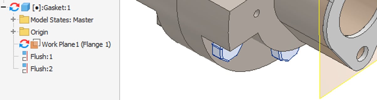
Figure 2.72: Adaptive symbols in the browser shown after the creation of the gasket
- In the top level of the assembly, create a new in-place component using Create as before, but this time select the top face of the recently created gasket to build the part on. Call the new component
Mating Plateand set Template tostandard (mm) .ipt. - Select Start 2D Sketch on the top face of the gasket and select Project Geometry, as shown in Figure 2.73:
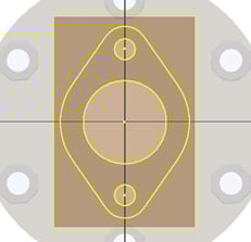
Figure 2.73: Projected sketch on top of the gasket for the creation of the mating plate
- Select Finish Sketch, and then select Extrude. Extrude the profiles shown in Figure 2.74 by
3.5 mm. Select OK to complete the operation.

Figure 2.74: Extrusion of the mating plate
- All additional adaptive parts have now been created. To observe the adaptivity, we will make changes to the original flange coupling components and observe how the newly created parts adapt:
- Right-click on Flange 1 from the Model Browser and select Edit.
- Expand the Extrusion 2 node and right-click on Sketch2, then select Edit Sketch.
- Change the dimension of the small hole to
2 mm; simply double-click Dimension and type the new value. The sketch holes update on completion.
- Select Exit Sketch, then select Return to return to the top-level assembly.
The Mating Plate and Gasket holes have now automatically updated to show the holes as 2 mm. No manual design work was required to complete this.
- In the Model Browser, click Flange 1 | Extrusion 2, right-click Sketch2, then edit the value back from
2 mmto5 mm. Exit and return to the top-level assembly and the parts will update, demonstrating adaptivity again.
This recipe is complete. You have created adaptive parts from an existing part file in the context of an assembly using the adaptive part modeling methodology.
Model credits
The model credits for this chapter are as follows:
- Shock Absorber (by Suriya SB) https://grabcad.com/library/shock-absorber-370/details?folder_id=10235721
- Crane Hook (by Lou Kaminski) https://grabcad.com/library/crane-hook-225
- Flange Coupling (by Vũ Chí Tường) https://grabcad.com/library/flange-coupling-144
