


 Download code from GitHub
Introduction to Client/Server Networking
This book is an introduction to writing networking applications in Rust. This title begs two questions: why should anyone care about networking? And why would anyone want to write networking applications in Rust? We attempt to answer the first question in this chapter. We will introduce Rust and network programming using Rust in subsequent chapters. Firstly, in this chapter, we will start with a bit of history and try to understand how network architecture evolved over the last hundred years. In subsequent sections, we will see how modern networks are layered and addressed. Afterwards, we will describe common service models used in networking. We will end with a summary of networking-related programming interfaces that Linux exposes. Note that this book deliberately ignores network programming in other operating systems and focuses only on Linux for the sake of simplicity. While the Rust compiler is platform-agnostic, there can be cases where some things are different in other platforms compared to Linux. We will point out those differences as we progress.
In this chapter, we will cover the following topics:
- History of networking: why and how networks came into use and how the internet evolved
- Layering in networks: how layering and encapsulation works
- Addressing: how networks and individual hosts are uniquely identified on the internet
- How IP routing works
- How DNS works
- Service models for data delivery
- The network programming interface in Linux
A brief history of networks
The modern internet has revolutionized how we communicate with one another. However, it had humble beginnings in the Victorian era. One of the earliest precursors to the internet was telegraph networks which were operational as early as 1850. Back then, it used to take 10 days to send a message from Europe to North America by sea. Telegraph networks reduced that to 17 hours. By the late 19th century, the telegraph was a fully successful communication technology that was used widely in the two world wars. Around that time, people started building computers to help in cracking enemy codes. Unlike our modern mobile phones and laptops, those computing machines were often huge and needed specialized environments to be able to operate smoothly. Thus, it was necessary to put those in special locations while the operators would sit on a terminal. The terminal needed to be able to communicate with the computer over short distances. A number of local area networking technologies enabled this, the most prominent one being Ethernet. Over time, these networks grew and by the 1960s, some of these networks were being connected with one another to form a larger network of networks. The Advanced Research Projects Agency Network (ARPANET) was established in 1969 and it became the first internetwork that resembles the modern internet. Around 1973, there were a number of such internetworks all around the world, each using their own protocols and methods for communication. Eventually, the protocols were standardized so that the networks could communicate with each other seamlessly. All of these networks were later merged to form what is the internet today.
Since networks evolved in silos all around the world, they were often organized according to geographical proximity. A Local Area Network (LAN) is a collection of host machines in small proximity like a building or a small neighborhood. A Wide Area Network (WAN) is one that connects multiple neighborhoods; the global internet is at the top of the hierarchy. The next picture shows a map of the ARPANET in 1977. Each node in this map is a computer (a server, in today's terms). Most of these were located in large universities like Stanford or at national laboratories like Lawrence Berkeley (source: https://commons.wikimedia.org/wiki/File:Arpanet_logical_map,_march_1977.png).

Layering in networks
Computer science often focuses on subdividing a problem into smaller, hopefully independent components that can be solved in isolation. Once that is done, all that is needed is a set of rules on how those components should communicate to have a solution to the larger problem. This set of rules, along with a pre-agreed data format, is called a protocol. A network is composed of a number of layers, each of which has a fixed purpose. Thus, each of these layers run one or many protocols, forming a stack of protocols. In the early days of networking, different people implemented their networks in different ways. When the internet was conceived, there was a need to make these networks communicate seamlessly. Since they were constructed differently, this turned out to be difficult.
There was a clear need to agree on standard protocols and interfaces to make the internet work. The first attempt at standardizing networking protocols was in 1977, which led to the OSI model. This model has the following layers:
- Physical layer: It defines how data is transmitted in the physical medium in terms of its electrical and physical characteristics. This can either be by wire, fiber optic, or a wireless medium.
- Data link layer: It defines how data is transmitted between two nodes connected by a physical medium. This layer deals with prioritization between multiple parties trying to access the wire simultaneously. Another important function of this layer is to include some redundancy in the transmitted bits to minimize errors during transmission. This is referred to as coding.
- Network layer: It defines how packets (made up of multiple units of data) are transmitted between networks. Thus, this layer needs to define how to identify hosts and networks uniquely.
- Transport layer: It defines mechanisms to reliably deliver variable length messages to hosts (in the same or different networks). This layer defines a stream of packets that the receiver can then listen to.
- Session layer: It defines how applications running on hosts should communicate. This layer needs to differentiate between applications running on the same host and deliver packets to them.
- Presentation layer: It defines common formats for data representation so that different applications can interlink seamlessly. In some cases, this layer also takes care of security.
- Application layer: It defines how user-centric applications should send and receive data. An example is the web browser (a user-centric application) using HTTP (an application layer protocol) to talk to a web server.
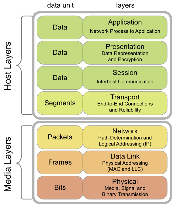
The following figure shows a visual representation of this model (source: https://commons.wikimedia.org/wiki/File:Osi-model-jb.svg). This also shows two vertical classifications, the host running the network stack and the physical media (including the wire and the network device). Each layer has its own data unit, the representation of the information it works on, and since each layer encapsulates the one below it, the data units encapsulate too. A number of bits form a frame, a number of frames form a packet, and so on, to the top:
While OSI was working on standardizing this model, Defense Advanced Research Projects Agency (DARPA) came up with a full implementation of the much simpler TCP/IP model (also known as the IP (Internet Protocol) suite). This model has the following layers, from closest to the physical medium to the farthest:
- Hardware interface layer: This is a combination of layers one and two of the OSI model. This layer is responsible for managing media access control, handling transmission and reception of bits, retransmission, and coding (some texts on networking differentiate between the hardware interface layer and the link layer. This results in a five layer model instead of four. This hardly matters in practice, though.)
- IP layer: This layer corresponds to layer three of the OSI stack. Thus, this layer is responsible for two major tasks: addressing hosts and networks so that they can be uniquely identified and given a source and a destination address, and computing the path between those given a bunch of constraints (routing).
- Transport layer: This layer corresponds to layer four of the OSI stack. This layer converts raw packets to a stream of packets with some guarantees: in-order delivery (for TCP) and randomly ordered delivery (for UDP).
- Application layer: This layer combines layers five to seven of the OSI stack and is responsible for identifying the process, data formatting, and interfacing with all user level applications.
Note that the definition of what a particular layer handles changes as we move from one layer to another. The hardware interface layer handles collection of bits and bytes transmitted by hosts, the IP layer handles packets (the collection of a number of bytes sent by a host in a specific format), the transport layer bunches together packets from a given process on a host to another process on another host to form a segment (for TCP) or datagram (for UDP), and the application layer constructs application specific representations from the underlying stream. For each of these layers, the representation of data that they deal with is called a Protocol Data Unit (PDU) for that layer. As a consequence of this layering, when a process running on a host wants to send data to another host, the data must be broken into individual chunks. As the chunk travels from one layer to another, each layer adds a header (sometimes a trailer) to the chunk, forming the PDU for that layer. This process is called encapsulation. Thus, each layer provides a set of services to layers above it, specified in the form of a protocol.
The modern internet exhibits a form of geographical hierarchy. Imagine a number of homes which are served by a number of Internet Service Providers (ISPs). Each of these homes is in a LAN (either via Ethernet, or more commonly, Wi-Fi). The ISP connects many such LANs in a WAN. Each ISP has one or many WANs that they connect to form their own network. These larger networks, spanning cities, which are controlled by a single business entity, are called Administrative Systems (AS). Routing between multiple ISPs is often more complex than regular IP routing since they have to take into account things like trading agreements and so on. This is handled by specialized protocols like the Border Gateway Protocol (BGP).
As mentioned before, one of the earliest and most successful networking technologies is Ethernet. First introduced in 1974, it quickly became the predominant technology for LAN and WAN due to its low cost and relative ease of maintenance. Ethernet is a shared media protocol where all the hosts must use the same physical medium to send and receive frames. Frames are delivered to all hosts, which will check if the destination MAC address (these addresses will be described in the next section) matches its own address. If it does, the frame is accepted, otherwise, it is discarded. Since the physical medium can only carry one signal at any given moment, there is a probability that frames might collide in transit. If that does occur, the sender can sense the collision by sensing transmission from other hosts while it is transmitting its frame. It then aborts the transmission and sends a jam signal to let other hosts know of the collision. Then, it waits for an exponentially backed off amount of time and retries the transmission. After a fixed number of attempts, it gives up if the transmission does not succeed.
This scheme is called carrier-sense multiple access with collision detection (CSMA/CD). One problem with Ethernet is its relatively short range. Depending on the physical wiring technology used, the maximum length of an Ethernet segment varies between 100 m to 500 m. Thus, multiple segments must be connected to form a larger network. The most common way of doing that is using layer two switches between two adjacent Ethernet segments. Each port of these switches forms different collision domains, reducing the overall probability of collisions. These switches can also monitor traffic to learn which MAC addresses are on which ports so that eventually, they will send out frames for that MAC address only on that port (referred to as a learning switch). In modern homes, Wi-Fi is often the dominant LAN technology compared to Ethernet.
Addressing in networks
We have seen why it is important to identify hosts and networks uniquely to be able to deliver packets reliably. Depending on the scale, there are three major ways of doing this; we will discuss each of those in this section. The end to end process of IP routing will be discussed in the next section. One interesting fact to note is that for each of these addressing modes, one or more addresses are reserved for special use. Often, these are marked by a known set of bits being on or off in a known pattern:
- Ethernet address: This is also known as a Media Access Control (MAC) address. It is a 48-bit long unique identifier assigned to a network device (usually stored on the card) that is used to identify it in a network segment. Usually, these are programmed by the network card manufacturer, but all modern OS's allow one to modify it. The standard way of writing Ethernet addresses are in six groups of two hexadecimal digits (01-23-45-67-89-ab-cd-ef). Another common way is to use a colon to separate the digits (01:23:45:67:89:ab:cd:ef). A few special sequences of bits are reserved for addressing special cases: the sender can request that an Ethernet frame should be received by all hosts in that segment by setting the least significant bit of the first octet to 1; this is called multicasting. If that particular bit is set to 0, the frame should be delivered to only one receiver. Today, these are used widely with Ethernet and Wi-Fi.
- IP address: This is an address assigned to each device in an IP network. The original IP address standard (IPv4) defined 32-bit addresses in 1980. However, by 1995, it was obvious that the total number of available addresses on the internet is not enough to cover all devices. This led to the development of IPv6, which expanded the address space to 128 bits. The standard way of dealing with a group of IP addresses is using the CIDR notation, for example, 192.168.100.1/26 (IPv4). The decimal number after the slash counts the number of leading 1s in the network mask. Thus, in this particular case, there are 2^(32-26) = 64 addresses in the network starting from 192.168.100.0 to 192.168.100.63. The Internet Assigned Numbers Authority (IANA) assigns blocks of publicly routable IP addresses to organizations. A number of IPv4 and v6 addresses are reserved for various purposes like addressing in private networks and so on. In a home network (which will always use special private range addresses), these are assigned by the Dynamic Host Configuration Protocol (DHCP) by the Wi-Fi router.
- Autonomous system number: This is a 32-bit number used to uniquely identify autonomous systems. Like IP addresses, these are assigned and maintained by the IANA.
Apart from these, communication between hosts often uses a port number to distinguish between processes. When the OS allocates a specific port to a process, it updates its database of the mapping between process identifier and port number. Thus, when it receives incoming packets on that port, it knows what process to deliver those packets to. In case the process has exited by that time, the OS will drop the packets and in the case of TCP, initiate closing of the connection. In the subsequent sections, we will see how TCP works in practice.
A range of port numbers between 0 and 1024 are reserved for common services by the OS. Other applications are free to request any port above 1024.
How IP routing works
To understand how IP routing works, we must first begin with the structure of IPv4 addresses. As described in the last section, these are 32 bits in length. They are written in a dotted decimal notation in groups of 4 bytes (for example, 192.168.122.5). A given number of bits in that network prefix is used to identify the network where the packet should be delivered, and the rest of the bits identify the particular host. Thus, all hosts in the same network must have the same prefix. Conventionally, the prefix is described in the CIDR notation with the starting address and the number of bits in the network portion of the address separated by a slash (192.168.122.0/30). The number can then be used to find out how many addresses are available for hosts in the network (in this case, 2^(32-30) = 4). Given an IP address and a prefix, the network address can be extracted by bitwise-ANDing the address with a mask of all 1s in the network portion. Calculating the host address is just the reverse; we will need to AND with the network mask's logical negation (the host mask), which has all 0s in the network portion and all 1s in the host portion. Given an address and a prefix like 192.168.122.5/27, we will compute these as shown in the following figure. Thus, for the given CIDR, the network address is 192.168.122.0 and the host address is 0.0.0.5:

There are two broad classes of IP address; some blocks of addresses can be routed in the public internet, these are called public IP addresses. Some other blocks can only be used in private networks that do not directly interface with the internet, these are called private addresses. If a router on the internet receives a packet that is destined for a private IP address, it will have to drop that packet. Other than these two, IP addresses are also classified on various parameters: some are reserved for documentation only (192.0.2.0/24), some are reserved for point to point communication between two hosts (169.254.0.0/16), and so on. The Rust standard library has convenience methods to classify IP addresses according to their types.
All routers maintain a routing table which maps prefixes to the outgoing interface of the router (while a router administrator might decide to store individual addresses instead of prefixes, this will quickly lead to a large routing table in a busy router). An entry in the table basically says If a packet needs to go to this network, it should be sent on this interface. The next host that receives the packet might be another router or the destination host. How do routers figure out this table? Multiple routers run routing protocols between those which compute those tables. Some common examples are OSPF, RIP, and BGP. Given these primitives, the actual routing mechanism is fairly simple, as shown in the next diagram.
An interesting aspect of IP is the use of the Time To Live (TTL) field, this is also known as hop limit. The host sends out packets with a fixed value of TTL (usually 64). Each router the packet crossed decreases the TTL. When it reaches 0, the packet is discarded. This mechanism ensures that packets are not stuck in an infinite loop between routers:

Note that while trying to match the prefix to routes in the routing table, multiple routes might match. If that happens, the router must select the most specific match and use that for forwarding. Since the most specific routes will have the maximum number of leading 1s, and hence the largest prefix, this is called the longest prefix match. Say our router has the following routing table, as shown in the diagram. eth1, eth2, and eth3 are three network interfaces attached to our router, each having a different IP address in different networks:

At this point, if our device gets a packet that has a destination address set to 192.168.1.33, all three prefixes have this address but the last one is the largest of the three. So, the packet will go out through eth3.
A lot of what we described so far about IPv4 addresses does not change for IPv6, except, of course, it has a larger address space of 128 bits. In this case, the length of the network mask and the host mask depends on the address type.
One might be wondering, how do routers construct the routing table? As always, there are protocols to help with that. Routing protocols are of two major types: interior gateway protocols which are used for routing inside an autonomous system, and exterior gateway protocols which are used in routing between autonomous systems; an example of the latter is BGP. Interior gateway protocols can again be of two types, depending on how they look at the whole network. In link state routing, each router participating in the protocol maintains a view of the whole network topology. In distance vector routing, each router only knows about its one hop neighbors. An example of the former is the Routing Information Protocol (RIP) and of the latter is Open Shortest Path First (OSPF). Details about these are beyond the scope of this book. However, we can note that the common theme among all the routing protocols is that they work by exchanging information between routers. Thus, they have their own packet formats for encapsulating that information.
How DNS works
Note that it's impossible for anyone to remember the IP address of each and every service on the internet. Fortunately, there is a protocol for that! The Domain Name Server (DNS) solves this problem by maintaining a map of a human readable hierarchical name to the IP address of the service in a distributed database. Thus, when a user enters http://www.google.com in their browser and hits the Enter key, the first step is to look up the IP address of the name www.google.com using DNS. The next figure shows the steps necessary in such a query. In this discussion, we will use the names local DNS resolver, local DNS server, and local DNS nameserver interchangeably:

An application that needs to resolve a name will use a system call like getaddrinfo. This essentially asks the OS to go ahead and resolve the name. This step is not shown in the figure. The next steps are as follows:
- Typically, each computer in a network will have a local DNS server configured in the file /etc/resolv.conf. In most cases, this points to the ISP's DNS server. This might also point to the home Wi-Fi router's DNS server. In that case, the DNS will transparently proxy requests to the ISP's DNS server. The OS will then query that server, asking the IP of the given name www.google.com.
- The local DNS server will, in turn, ask the same question to a pre-populated list of root name servers. These servers are maintained by ICANN and their addresses are well-known. They maintain addresses for the top level domain name servers. This means that they know the addresses of namesevers for the .com domain.
- In this step, the root name server replies with the addresses of TLD name servers for the .com domain. These servers maintain a list of addresses for name servers in their own domains.
- The local DNS server then contacts one of those and asks the same question.
- The TLD name server replies back with the addresses of servers in the google.com domain. An admin of the google.com domain maintains a bunch of nameservers for that domain. Those nameservers have full authority over all records in that domain, and each of those records are marked authoritative to indicate that.
- The local DNS server then asks one of those the same question.
- (Hopefully) that server does know the address of www.google.com. If it does, it prepares a response, marks it as authoritative, and sends it back to the local DNS server. The answer can also have a time to live associated with it so that the local DNS server can cache it for future use and evict it after the given time is over. If it does not, name resolution will fail and it will send back a special response called NXDOMAIN.
- The local DNS server then sends back the same response to the OS, which delivers it to the application. The local server marks the response as non-authoritative, indicating that it got that answer from somewhere else.
Interestingly, DNS is like asking a friend for someone's address, who then says I do not know, but I know someone who knows someone who knows someone who might know. I can find out for you! They then go and ask around and return with a reply.
DNS packets are often very small since they have a small question and answer along with some control information, and since DNS does not need very high reliability from the transport layer, this makes it an ideal candidate for using UDP (described in the next section). However, most implementations include an option to fall back to TCP if the transport is too unreliable.
Common service models
For two hosts to communicate via a network, they will need to send messages to each other. There are two models of exchanging messages, and each has specific usecases where they work best. In this section, we will explore these. Note that the service models are properties of the protocols and that they set expectations around what a consumer should expect from them.
Connection-oriented service
The service a protocol provides to its consumers is connection oriented when each party involved negotiates a virtual connection before sending the actual data. During the setup process, a number of parameters about the connection must be agreed upon. This is analogous to the older wired telephone systems, where a dedicated connection is set up between the two hosts. In modern networks, an example is TCP. The PDU for TCP is a segment, which consists of a header and a data section. The header has a few fields which are used to transition between states of the protocol state machine. The next figure shows what the TCP header looks like in practice. Each of the rows in this figure are of 32 bits (thus, each row is two octets), and some are divided into multiple segments:

We will look at a few of these which are used for manipulating the connection between hosts:
- Control bits (flags) are a set of 9 bits that are used for various purposes. The flags of interest here are SYN, ACK, FIN, and RST. SYN triggers a synchronization of sequence numbers. The ACK flag indicates that the receiver should care about the corresponding acknowledgment number. The FIN flag starts the process of tearing down a connection. The RST flag resets the connection in case of an error.
- The sequence number is a 32-bit field which is used to reorder messages at the receiver. When the SYN flag is set (which should be the case only for the first packet in a connection), the sequence number is the initial sequence number; otherwise, it is the sequence number accumulated so far.
- The acknowledgement number is a 32-bit field which is used to enable reliable delivery of messages. If the ACK flag is set, this value is the next sequence number that the sender is expecting.
Before two hosts running TCP can start exchanging data, they must do a three-way handshake to establish a connection. This works like this: the client that wants to initiate communication sends a SYN packet to the server. The sequence number is set to a random value and the SYN flag is set to 1. The server responds with a packet that has both SYN and ACK set to 1. This packet has the acknowledgment number set to one more than what it got from the client, and the sequence number is set to a random number. Finally, the client responds with a packet that has the ACK flag set, the sequence number set to the received acknowledgement number in the last step, and the acknowledgement number is set to one more than the sequence number in the previous step. After this is done successfully, both the client and the server have agreed on sequence and acknowledgement numbers. The advantage of this model is that is has a reliable connection where both the sender and the receiver knows what to expect. The sender can tune the rate of sending data, depending on how fast or slow the receiver is or how congested the network is. The disadvantage here is the higher connection setup costs. Assuming it takes 100 ms to send a packet to a host in another continent, we will need to exchange at least 3 packets before we can begin sending data. That amounts to a delay of 300 ms. While this might not look like a lot, remember that at any given point, a laptop being used for accessing Facebook might have thousands of connections open to servers all over the world. The connection oriented service model works fine for a large number of use cases, but there are a few cases where the overhead is either significant or unnecessary. An example is video streaming. In this case, a few missing packets do not cause a huge problem since no one notices a small number of misaligned pixels in the video. These applications prefer a connectionless model, as described below.
Connectionless service
The second case here is a connectionless service. This is used when multiple messages bear no relation to one another, and thus these protocols do not need any connection negotiation step before sending any data. An example of this is UDP, which provides no guarantees of the sequence or reliability of transmitted messages (it does, however, have a checksum field to guarantee the correctness of the datagram). One should note that the protocol running above UDP is always free to implement reliability if that is desired. Interestingly, IP routing is also a connectionless service. The UDP header is shown as follows:

It's easy to see that the header here is far smaller than a TCP header. It also lacks a number of fields that TCP uses to manage the connection and tune it according to network congestion and so on. Since UDP does not have those fields, it cannot provide those guarantees.
The network programming interface in Linux
In this section, we will see how Linux (and a lot of other members of the Unix family) implement common network patterns, and how a user will interact with those while writing networking applications. All discussions in this section will be strictly based on a Linux-like OS with the standard C library (glibc). The Portable OS Interface (POSIX) standard includes all of these, making them portable to any POSIX compliant OS. All functions and data structures here follow C (and C++) coding conventions, but as we will see later, some of these are available in Rust as well through libc bindings.
The most important networking primitive that the OS provides is a socket. Now, what is a socket? A socket is a glorified file descriptor, a unique ID that is assigned to each file in a Unix-like OS. This follows from the Unix philosophy that everything should be a file; treating the connection between two hosts over a network as a file enables the OS to expose it as a file descriptor. The programmer is then free to use traditional I/O-related syscalls to write and receive from that file.
Now, obviously, a socket needs to hold some more data than a regular file descriptor. For instance, it needs to track the remote IP and port (and also the local IP and port). Thus, a socket is a logical abstraction for the connection between two hosts, along with all information needed to transfer data between those hosts.
The standard library also provides a few system calls for interacting with sockets. Some of those are socket specific and some of them are generic I/O syscalls that support writing to file descriptors. Since a socket is basically a file descriptor, those can be used to interact with sockets. Some of these are described in the next image. Note that not all applications will need to use all of these syscalls. A server, for instance, will need to call listen to start listening for incoming connections once it has created a socket. It will not need to call connect for that same connection:

Let's look at the signatures of these syscalls in more detail. Unless otherwise mentioned, all of these return 0 on success or -1 on failure, and set the value of errno accordingly.
int socket(int domain, int type, int protocol);
The first parameter for the socket syscall tells it what kind of communication socket will be used. Common types are AF_INET for IPv4, AF_INET6 for IPv6, AF_UNIX for IPC, and so on. The second parameter tells it what type of socket should be created, common values being SOCK_STREAM for a TCP socket, SOCK_DGRAM for a UDP socket, SOCK_RAW for a raw socket which provides direct access to the network hardware at packet level, and so on. The last parameter denotes the layer 3 protocol to be used; in our case, this is exclusively IP. A complete list of supported protocols is available in the file /etc/protocols.
On success, this returns a new file descriptor that the kernel assigns to the socket created.
int bind(int sockfd, const struct sockaddr *addr, socklen_t addrlen);
The first parameter for bind is a file descriptor, generally one returned by the socket system call. The second parameter is the address to be assigned to the given socket, passed as a pointer to a structure. The third parameter is the length of the given address.
int listen(int sockfd, int backlog);
listen is a function that takes in the file descriptor for the socket. Note that when an application is listening for incoming connections on a socket, it might not be able to read from it as fast as packets arrive. To handle cases like this, the kernel maintains a queue of packets for each socket. The second parameter here is the maximum length of the queue for the given socket. If more clients are trying to connect after the given number here, the connection will be closed with a connection refused error.
int accept(int sockfd, struct sockaddr *addr, socklen_t *addrlen);
This call is used to accept connections on TCP sockets. It takes a connection of the queue for the given socket, creates a new socket, and returns the file descriptor for the new socket back to the caller. The second argument is a pointer to a socket address struct that is filled in with the info of the new socket. The third argument is its length.
int connect(int sockfd, const struct sockaddr *addr, socklen_t addrlen);
This function connects the socket given by the first argument to the address specified in the second argument (the third argument being the length of the address struct).
ssize_t send(int sockfd, const void *buf, size_t len, int flags);
This is used to send data over a socket. The first argument tells it which socket to use. The second argument is a pointer to the data to be sent, and the third argument is its length. The last argument is bitwise OR of a number of options which dictates how packets should be delivered in this connection.
This system call returns the number of bytes sent on success.
ssize_t recv(int sockfd, void *buf, size_t len, int flags);
This one is the counterpart of send. As usual, the first argument tells it which socket to read from. The second argument is a pointer to an allocated space where it should write the data it reads, and the third argument is its length. flags here has the same meaning as in the case of send.
This function returns the number of bytes received on success:
int shutdown(int sockfd, int how);
This function shuts down a socket. The first argument tells it which socket to shut down. The second argument dictates if any further transmission or reception should be allowed before the socket is shut down.
int close(int fd);
This system call is used to destroy file descriptors. Consequently, this can be used to close and clean up a socket as well, given its file descriptor number. While shutdown allows the socket to receive pending data and not accept new connections, a close will drop all existing connections and cleanup resources.
Note that a lot of syscalls described above are blocking, which means they block the thread they are invoked in waiting for the given operation to finish. For example, the read syscall will block on the socket if enough data is not available to fill the buffer provided. Often, this is not desirable, especially in modern multithreaded environments where a blocking call will not be able to take full advantage of the computing power available since the thread will loop around doing nothing useful.
Unix provides some more syscalls that enable asynchronous, non-blocking applications using the standard C library. There are two standard ways of doing this:
- Using the select system call: This syscall monitors a list of given sockets and lets the caller know if any of those has data to read from. The caller can then retrieve those file descriptors using some special macros and read from those.
- Using the poll system call: The high-level semantics here is similar to that of select: it takes in a list of socket file descriptors and a timeout. It monitors those asynchronously for the given timeout, and if any of those have some data, it lets the caller know. Unlike select, which checks for all conditions (readability, writability, and error) on all file descriptors, poll only cares about the list of file descriptors and conditions it receives. This makes poll easier to work with and faster than select.
In practice, however, select and poll are both very slow for applications which might need to monitor a lot of sockets for connections. For such applications, either epoll or an event-based networking library like libevent or libev might be more suitable. The gain in performance comes at the cost of portability; those libraries are not available in all systems since they are not part of the standard library. The other cost is complexity in writing and maintaining applications based on external libraries.
In the following section, we will walk through the state transitions of a TCP server and client that is communicating over a network. There are some idealistic assumptions here for the sake of simplicity: we assume that there are no intermediate errors or delays of any kind, that the server and the client can process data at the same rate, and that neither the server nor the client crash while communicating. We also assume that the client initiates the connection (Active open) and closes it down (Active close). We do not show all the possible states of the state machine since that will be way too cumbersome:

Both the server and the client start from the CLOSED state. Assuming the server starts up first, it will first acquire a socket, bind an address to it, and start listening on it. The client starts up and calls connect to the server's address and port. When the server sees the connection, it calls accept on it. That call returns a new socket from which the server can read data from. But before actual data transmission can occur, the server and the client must do the three-way handshake. The client initiates that by sending a SYN, the server reads that, responds with a SYN + ACK message, and goes to the SYN_RCVD state. The client goes to the SYN_SENT state.
When the client gets the SYN + ACK, it sends out a final ACK and goes to the ESTABLISHED state. The server goes to ESTABLISHED when it gets the final ACK. The actual connection is established only when both parties are in the ESTABLISHED state. At this point, both the server and the client can send and receive data. These operations do not cause a state change. After some time, the client might want to close the connection. For that, it sends out a FIN packet and goes to the FIN_WAIT_1 state. The server receives that, sends an ACK, and goes to the CLOSE_WAIT state. When the client gets that, it goes to the FIN_WAIT_2 state. This concludes the first round of connection termination. The server then calls close, sends out a FIN, and goes to the LAST_ACK state. When the client gets that, it sends out an ACK and goes to the TIME_WAIT state. When the server receives the final ACK, it goes back to the CLOSED state. After this point, all server resources for this connection are released. The client, however, waits for a timeout before moving on to the CLOSED state where it releases all client-side resources.
Our assumptions here are pretty basic and idealistic. In the real world, communication will often be more complex. For example, the server might want to push data, and then it will have to initiate the connection. Packets might be corrupted in transit, causing either of the parties to request retransmission, and so on.
Summary
This chapter started with motivations for writing networking applications in the modern world. We also took a look at how networking evolved. We studied common networking technologies and ideas, and looked at how they work together; starting from simple IP routing and DNS to TCP and UDP. We then studied how Linux (and POSIX) in general supports synchronous and asynchronous network programming.
In the next chapter, we will look at Rust and try to understand its benefits over existing platforms. Having motivated both networking and Rust, we will move on to network programming using Rust.