


 Download code from GitHub
The Arduino
Have you ever looked at a gadget and wondered how it worked? Do you want to create your own cool and exciting electronics project but do not know how to get started? Your decision to start reading this book is an excellent first step.
In this book, we will teach you everything you need to get started with the Arduino. Everything from basic electronics and prototyping to setting up the Arduino development environment and programming is covered. This book also has numerous sample projects to show you how to use this knowledge with real-world examples. Before we get to all that fun stuff, let's a look at the Arduino itself and get familiar with it.
In this chapter, you will learn:
- What the Arduino boards are
- How to power the Arduino boards
- What Arduino shields are
- What the pins on the Arduino boards do
- Learn about generic and compatible Arduino boards
Arduino is a company, development boards, community and a way of thinking. As you will soon find out, Arduino is also the name of a bar in northern Italy. While we could begin this book by writing several chapters on everything that the Arduino name stands for, that is not what this book is about. This book is about teaching you how to use the Arduino development board to build fun and exciting projects. Anywhere in this book, unless noted otherwise, when we refer to the Arduino we will be referring to the Arduino development boards. However, we do believe to really understand the Arduino board, you should at least have a basic understanding of its history; therefore, we will start off by giving you a brief history of the board and its predecessors.
History of the Arduino
In 2003 Hernando Barragan started working on a project called Wiring for his master's thesis at the Interaction Design Institute Ivrea (IDII) in Italy. At that time students used a microcontroller board that cost USD $100 and needed additional hardware and software to use. Massimo Banzi and Casey Reas, who is known for work on the Processing language, were supervisors for his thesis. The name was Wiring: Prototyping Physical Interaction Design.
The purpose of the thesis was to create a low-cost and easy-to-use tool so non-engineers could create digital projects. To do this, Hernando wanted to abstract away the complicated details of the electronics to let the user focus on their project. This meant that it had to be work by simply plugging the device into a host computer and have an easy-to-use interface to program it.
The first prototype used the Parallax Javelin Stamp microcontroller, which used a subset of the Java programming language. This solution required the Parallax proprietary tools to compile, link and upload the projects to the microcontroller; therefore, it did not meet the requirements of the project because the wiring was going to be an open source project.
The second prototype used the Atmel ARM-based 91R40008 microcontroller. Hernando obtained better results with this new microcontroller; however, he determined that the microcontroller was far too complex, and it was almost impossible to solder it by hand to a circuit board.
The third prototype used the Atmel ATmega128 microcontroller with the MAVRIC microcontroller board. Hernando had great success using this microcontroller. He used a tool written by Brian Dan called Avrdude to easily upload new programs to the board.
FTDI's hardware was chosen for the USB to serial communication because it had easy-to-obtain drivers for Linux, Windows and macOS platforms. This allowed the Wiring project to be compatible with all three major platforms.
In 2004, the IDII ordered and paid for 25 Wiring circuit boards. These boards were manufactured by SERP. They included the ATmega128 microcontroller, FTDI USB to serial hardware, onboard LED connected to a pin and serial RX/TX LEDs. Usability tests were performed using these boards and the results were great.
After graduating with distinction in 2004, Hernando moved back to his native Colombia to teach at the Universidad de Los Andes where he continues to work on Wiring. In May 2005, Hernando ordered 200 circuit boards and begin assembling the first Wiring boards outside of IDII. He sold these boards for approximately USD $60. By the end of 2005 Wiring was being used in various parts of the world.
Also, in 2005, the first Arduino board was created. The Arduino board used the less expensive ATmega128 microcontroller to reduce cost. The Arduino team forked the Wiring code and added support for this board.
The initial Arduino core team consisted of Massimo Banzi, David Cuartielles, Tom Igoe, Gianluca Martino and David Mellis. Hernando was not invited to participate in this project. There are several accounts from different individuals involved about why he was not invited.
The Arduino team strongly believed in open source hardware and software. They believed that by opening the platform up, many more people would have access to and be involved with it. Another reason for opening the platform up was that IDII had used up its funding and was going to be shut down. By open sourcing the platform they knew it would survive and would not be exploited by others.
The team initially decided on a price of USD $30 for the board. They figured it would make it easily accessible to students as well individuals. They also decided to make the board blue, which was different from most other boards at the time, which were green. Another design decision that helped add to the popularity of the board was giving it lots of input and output pins. Most boards at the time limited the number of I/O to reduce costs.
Initially, the team ordered 300 printed circuit boards to conduct a usability test. They handed these boards out to students at IDII with three simple instructions: look up the assembly instructions online, build your board and use it to create something. They had great success with this test because the students were able to assemble the boards and create numerous projects with it.
Shortly after this test, people began to hear about this board and wanted one for themselves. The project started to take off; however, it was still missing a name. While discussing the name, the team was having drinks at a local a bar frequented by Massimo Banzi. The bar's name was Bar Di Re Arduino and the new board became known as the Arduino.
What is the Arduino?
At the heart of the Arduino is the microcontroller. A microcontroller is a standalone, single-chip integrated circuit that contains a CPU, read-only memory, random access memory and various I/O busses. Most Arduino boards use the Atmel 8-bit AVR microcontroller.
The Arduino UNO R3, which is the primary board used in this book, uses the ATmega328 chip. This chip is an 8-bit RISC-based microcontroller that features 32 KB of flash memory with read-write capabilities, 1 Kbyte EEPROM, 2 Kbytes SRAM, 23-general purpose I/O lines and 32 general-purpose registers. Do not be too concerned if you do not understand all those specifications because we will be interacting with the microcontroller using the interface that the Arduino board provides us. It is good to know these specifications as you begin to develop more complex applications because they do put limits on what we can do.
All the hardware and software that make up the Arduino platform are distributed as open source and licensed under the GNU Lesser General Public License (LGPL) or the GNU General Public License (GPL). This allows for the manufacture and distribution of Arduino boards by anyone and has led to numerous generic, lower cost, Arduino compatible boards.
Touring the Arduino UNO R3
The Arduino is an open source hardware and software platform that is incredibly powerful yet easy to use. You can look at and download the code from any of the Arduino repositories on GitHub here: https://github.com/arduino. This platform has captured the imagination of electronic enthusiasts and the maker community everywhere. It enables people to inexpensively experiment with electronic prototypes and see their projects come to life. These projects can range from simply making an LED blink or recording the temperature to controlling 3D printers or making robots.
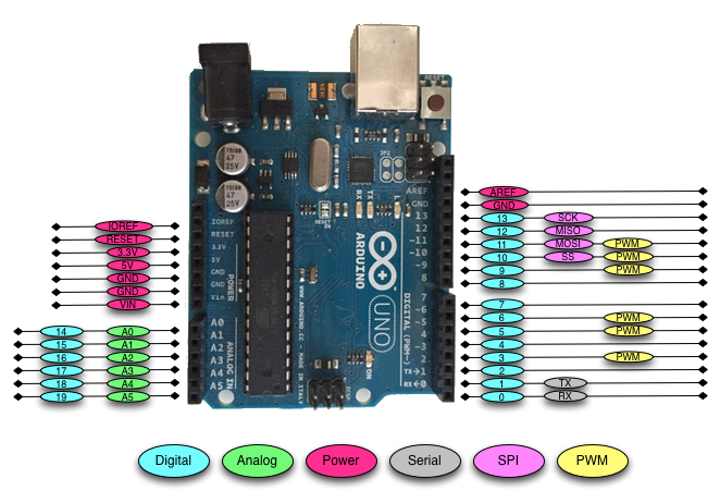
While there are numerous models of the Arduino, in this book we will primarily be using the very popular Arduino UNO R3 board. The following photograph shows the Arduino Uno's board layout with the main connectors identified:

As we can see, the Arduino Uno of today still uses the blue color that the original Arduino designers chose to help their boards stand out. The following is a list of major components of the Arduino Uno:
- DC supply Input: The DC supply input can be used with an AC-to-DC power adapter or a battery. The power source can be connected using a 2.1 mm center-positive plug. The Arduino Uno operates at 5 volts but can have a maximum input of 20 volts; however, it is recommended to not use more than 12V.
- Voltage Regulator: The Arduino uses a linear regulator to control the voltage going into the board.
- USB Port: The USB port can be used to power and program the board.
- RESET button: This button, when pressed, will reset the board.
- ICSP for USB: The in-circuit serial programming pins are used to flash the firmware on the USB interface chip.
- ICSP for ATmega328: The in-circuit serial programming pins are used to flash the firmware on the ATmega microcontroller.
- Digital and PWM connectors: These pins, labeled 0 to 13, can be used as either a digital input or output pins. The pins labeled with the tilde (~) can also be used for Pulse-Width Modulation (PWM) output.
- Analog In Connectors: The pins, labeled A0 to A5, can be used for analog input. These pins can be used to read the output from analog sensors.
- Power and External Reset: These pins in this header, provide ground and power for external devices and sensors from the Arduino. The Arduino can also be powered through these pins. There is also a reset pin that can be used to reset the Arduino.
- ATmega328: The microcontroller for the Arduino Uno board.
The Digital/PWM/Analog in/Power/Reset connectors are collectively known as the pin headers. The pins in these headers allow the Arduino to communicate with external sensors and other devices. Let's look at the different ways that we can power the Arduino board.
Powering the Arduino
The Arduino can be powered in one of three ways: through the VIN/GND pins, the DC Supply Input port or the USB port.
Using the VIN/GND pins to power the Arduino
The VIN and GND pins in the power and external reset header can be used to power the Arduino with an external battery. Powering the Arduino in this way is mainly used when we wish to connect a battery, in series, with a switch to turn the power to the Arduino on and off. The following photograph illustrates this:

It is not recommended that we power the Arduino in this manner unless we are looking for the most expensive and short-lived way to power the Arduino. We could use six AA batteries in series, which will provide the same voltage as the 9V battery in the preceding photograph but would give us approximately four times the capacity. It is still not recommended that we power the Arduino in this manner as it would be fairly expensive.
Unless there is a specific need to use a battery to power the Arduino, I would avoid using them.
Using the DC supply input to power the Arduino
The DC supply input connector can be used with an AC-to-DC power adapter or a battery to power the Arduino. The connector has a female 2.1 mm center-positive plug. While the Arduino operates at 5 volts a maximum input of 20 volts can be used; however, as was stated earlier, it is recommended to not use more than 12V.
We can use an AC-to-DC adjustable power adapter like the one shown in the following photograph to power the Arduino using the DC supply input connector:
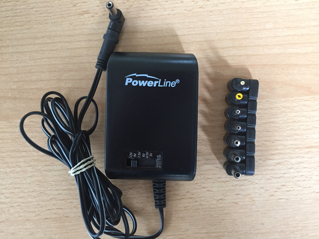
With this adapter, you can adjust the output power to the desired voltage. You can find power supplies similar to this online or at most stores that sell electronic items.
Using the USB connector to power the Arduino
Using the USB connector to power the Arduino is the way that I usually power it. It is by far the easiest and safest way to power the Arduino and the least expensive. You can power the Arduino directly from the USB port on your computer or from a USB rechargeable power bank like the one shown in the following photograph:

This is a very affordable and simple way to power the Arduino. It can also be used for robotic or similar projects that need the mobility to move around; however, we do need to be careful when we connect shields or other accessories to the Arduino that the USB connector can draw enough power. As an example, later in this book, we will look at the MOVI speech synthesizing and voice recognition shield that draws too much power for the Arduino to be powered by the USB connector while the shield is connected.
Now that we have mentioned Arduino shields, let's look at what they are and see the types of functionality they can provide.
Arduino shields
An Arduino shield is a modular circuit board that plugs directly into the pin headers of the Arduino board. These shields will add extra functionality to the Arduino board. If we are looking to connect to the internet, do speech recognition, control DC motors or add other functionality to the Arduino, there is probably a shield that can help us. While we are not required to use shields, they do make adding extra functionality to our Arduino boards very easy.
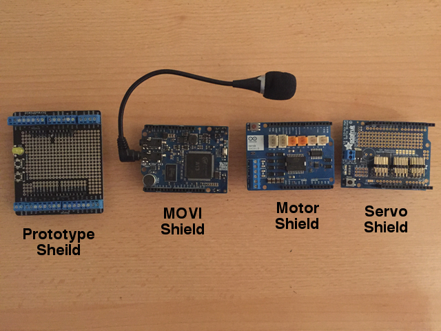
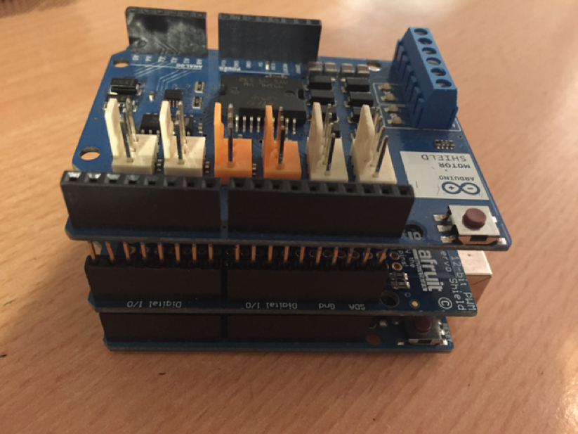
The following photograph shows examples of a few shields. We will be using shields in some of our sample projects later in this book:
A shield fits on top of the Arduino by plugging directly into the pin headers. We can also stack one shield on top of another if they do not use the same resources. Here is how an Arduino looks with two shields attached:
An Arduino shield makes it incredibly easy to add functionality to an Arduino Uno. Most shields usually have great documentation as well, which makes programming them also very easy. The drawback to shields is they usually cost more than purchasing the components and connecting them to the Arduino with a breadboard.
Some shields, such as the MOVI speech synthesizing and voice recognition shield and the Sparkfun Xbee radio module shield, add functionality that cannot simply be added as a single component. For functionality like this, a shield or an external circuit board would be required.
Let's take a closer look at the pin headers for the Arduino Uno R3.
Arduino pin
There is a total of 31 pins in the Arduino Uno pin headers. Most of these pins can be configured to perform different functions. The following diagram shows what the various pins can be used for:
Let's look at what the different pins do.
Digital pins
The digital pins on the Arduino are the ones that are used the most when connecting external sensors. These pins can be configured for either input or output. These pins default to an input state; therefore, when we are using a pin for input we do not need to explicitly declare them as input pins; however, it is good practice to do so because it will make it easier for someone reading our code to understand what the pin is being used for.
The digital pins will have one of two values: HIGH (1), which is 5V, or LOW (0), which is 0V. Once we start to program the Arduino, we will see how to read from or write to these pins.
Analog input pins
The Arduino Uno contains a built-in Analog-To-Digital (ADC) converter with six channels, which gives us six analog input pins. The ADC converts an analog signal into a digital value. While the digital pins have two values, either high or low, the analog input pins have values from 0 to 1023 relative to the reference value of the Arduino. The Arduino Uno has a reference value of 5V.
The analog input pins are used to read analog sensors such as rangefinders and temperature sensors. The six analog pins can also be configured as digital pins if we run out of digital pins in our project.
PWM pins
Where the analog input pins are designed to read analog sensors (input), the PWM pins are designed for output. PWM is a technique for obtaining analog results with digital output.
Since a digital output can be either on or off, to obtain the analog output the digital output is switch between HIGH and LOW rapidly. The percentage of the time that the signal is high is called the duty cycle. The following diagram illustrates this concept:

We have the ability to set the frequency of how fast the signal can switch between HIGH and LOW. This frequency is measured in Hertz and sets how many times the signal can switch per second. For example, if we set the frequency to 500 Hz, that would mean that the signal could switch 500 times a second.
We will be using the PWM pins for several examples in this book and will examine them more when we learn how to program the Arduino.
Power pins
The Arduino has several power pins. They are as follows:
- VIN: This pin is used when we power the Arduino board using an external power supply. This is the pin used in the Using the VIN/GND pins to power the Arduino section of this chapter.
- GND: These are the ground pins.
- 5V: This is 5V out and is used to power most sensors.
- 3.3V: This is 3.3V out and can be used to power sensors that are compatible with 3.3V. A list of some compatible 3.3V sensors can be found here: https://www.dfrobot.com/wiki/index.php/3.3V_Compatible_Device_List.
- Reset: This pin can be used to reset the Arduino board by an external source.
- ioref: This is the reference voltage for the board. For the Arduino, this will be 5V.
Serial pins
These pins can be used for serial communication. The RX (digital pin 0) is used to receive while TX (digital pin 1) is used to transmit. These pins are connected directly to the USB-to-TTL serial chip. One note, you should not connect these pins directly to an RS-232 serial port because you will damage your board.
SPI pins
The Serial Peripheral Interface (SPI) pins are used for a synchronous serial data protocol that is used by microcontrollers for communicating with peripheral devices. This protocol always has one master with one or more slave devices. The pins are:
- MISO: The Master in Slave out pin is used to send data from the slave to the master device.
- MOSI: The Master out Slave in the pin is used to send data from the master to the slave device.
- SCK: The serial clock synchronizes the data transmission and is generated by the master.
- SS: The slave select pin tells the slave to go active or to go to sleep. This is used to select which slave device should receive the transmission from the master.
Now that we have quickly looked at the pins on the Arduino Uno R3 let's look at some of the different Arduino boards.
Different Arduino boards
There are a number of different official Arduino boards and modules that can be used for various purposes. To see all the different boards, you can go to that Arduino product page (https://www.arduino.cc/en/Main/Products) where they list all the official Arduino boards.
While the Arduino Uno R3 is the most popular Arduino board within the maker community, the following lists some of the other popular boards:
Arduino Micro

The Arduino Micro is the smallest board in the Arduino family. It is based on the ATmega32U4 microcontroller. This board features 20 digital I/O pins of which 7 can be used for PWM output and 12 can be used as analog input. The Micro and the Nano (which we will see a little later) can be used for a project where the Arduino Uno may be too big.
Arduino Mega 2560

The Arduino Mega 2560 is designed for the most complex projects. It features 53 digital I/O pins, 16 analog input pins and 15 PWM output pins. It also has 4 serial UARTs for serial connections. If you want to create a complex project like a robot, the Mega is the board you will want to start with.
Lilypad

The Arduino Lilypad is designed for wearable projects. It can be sewn into fabrics and use power supplies and sensors that are also sewn into fabrics. The Lilypad is based on the ATmega168V or ATmega328V (low power versions). This board features 16 digital I/O, 6 analog inputs and 6 PWM outputs.
Arduino Nano

There are a lot of similarities between the Nano and the Micro. The Micro was released in 2012 while the Nano was released in 2008. The Nano features 14 digital I/O pins, 8 analog input pins and 6 PWM output pins. With those specifications, you may think that you should use the Micro board over the Nano however if you look at most online retailers like Amazon or eBay you can find the Nano for about half the price of the Micro.
You will also find that the Nano is easier to obtain than the Micro because there are so many generic Nano boards. We will also be using the Nano for some of the projects in this book.
Generic boards
At the beginning of this book, we noted that the Arduino is an open source hardware and software platform. All the original hardware design files are released under the Creative Commons Attribution Share-Alike license. This license allows both personal and commercial derivatives of all the Arduino boards if they credit Arduino and release their design under the same license. This has led to many lower price generic boards.
If you search for an Arduino board on most online retailer sites, the majority of the boards will not actually be genuine Arduino boards. If you look at the Arduino Uno board in the following photograph, you will notice an infinity sign with a plus (+) and minus (-) in it. That is the official Arduino logo and any board that has this logo is a genuine Arduino board.

In this book, we will be using mostly generic Arduino boards as they are cheaper and usually easier to obtain. The following photograph shows what some generic Arduino boards look like. The first photograph shows two generic Arduino Uno boards:

The next photograph shows a generic Arduino Mega 2560 board:

You will notice that these generic boards do not contain the Arduino logo; however, they still contain the name of the official board. While the previous generic boards look very similar to the official Arduino boards, that is not required. Some manufacturers chose to take the Arduino reference design and add additional functionality to their boards. The board in the following photograph is an example of this:

The DFRobot RoMeo BLE board is an Arduino-compatible robot control board with Bluetooth LE 4.0. This board takes the design of the Arduino Uno and adds a number of extra features, such as built-in Bluetooth and an integrated two-way DC motor driver.
No matter what your project is, you can probably find either a genuine Arduino board or a generic/compatible one that will fit your needs.
Summary
In this chapter, we gave a brief history of the Arduino, which included its development from a master's thesis paper to a full commercial project. This included a tour of some different Arduino boards. We also showed the different ways that the Arduino boards can be powered and gave a brief explanation of the various pin types.
In the next chapter, we will give you a brief introduction to electronics and commonly used components.