Download code from GitHub
Chapter 1: Introduction to Networking
Beginning a journey in the field of networking is an exciting one for everyone. I'm sure you are interested in learning about the operations of a computer and especially how the internet, the largest network, functions and grows. Networking is an ever-demanding field in Information Technology (IT); each day, organizations from healthcare providers, educational institutions, government agencies, and other industries are continuously expanding and improving their network infrastructure to support newer services and network traffic. Almost everyone is connected to the internet. Educators and businesses are using various online collaboration platforms to extend their reach to students and potential customers in a global market. All these amazing technologies are made possible by computer networks.
The Cisco Certified Network Associate (CCNA) 200-301 certification is designed to prepare you for associate-level networking roles in the IT industry. CCNA is one of the most popular certification requirements for almost every network engineering job, and there is a very good reason why. The CCNA certification is a foundational level certification with a lot of essential information; I know part of the name contains the word "associate", but that's just in the Cisco certification hierarchy structure since the next level is Cisco Certified Network Professional and so on. The CCNA is one of the most recommended certifications you can follow to begin your networking journey.
The CCNA will teach you how to design, implement, configure, and troubleshoot small- to medium-sized enterprise networks. You will learn to efficiently implement network access, IP connectivity, IP services, and security through an enterprise network. Additionally, gaining your CCNA certification will open up a whole new world of career opportunities as the certification itself is well-respected in the networking field.
Throughout this chapter, you will learn about the important history of how computer networks were developed and the era before the internet. Then, we will cover the early and current generation of the internet and explore how networking has become part of our daily lives. You will learn about communication technologies and networking protocols that are designed to help us connect with our loved ones, friends, and colleagues. You will also learn about the various sizes of networks and components such as routers and switches, which move messages from one device, across a network, to another person. Lastly, you'll learn about the various protocol suites that are built into each operating system and network device that sets the protocol for exchanging messages.
In this chapter, we will cover the following topics:
- Understanding the evolution of networking and the internet
- Understanding network sizes – SOHO, LAN, and WAN
- Learning about network protocol suites
- Understanding the functions of network devices
- Network topology architectures
Understanding the evolution of networking and the internet
In the pre-internet age, scientists, institutions, and other experts were working to create a network that could allow them to connect computers on a worldwide scale. Computer scientists began working on a model; the initial prototype was known as the Advanced Research Projects Agency Network (ARPANET).
ARPANET was developed in the 1960s. It was funded by the US Department of Defense (DoD) with the idea it would be used to connect universities and research centers. The network technology used on this prototype was packet switching. This allowed connected computers to send and receive data on a single network. However, ARPANET was not resilient enough to allow multiple channels of communication on the network.
The US Defense Advanced Research Projects Agency (DARPA) developed the Transmission Control Protocol/Internet Protocol (TCP/IP) suite, which was adopted by ARPANET in the early 1980s. The US DOD called it the official standard computer networking. With the adoption of TCP/IP, ARPANET began to evolve into much larger networks, allowing other organizations to be interconnected, and became what we commonly refer to as the internet today.
The internet is a worldwide collection of many interconnected networks, such as Wide Area Networks (WANs) and Local Area Networks (LANs). Each organization or person who connects a device to the internet simply extends the network (internet), so the internet is continuously growing as more devices are going online. Later in this chapter, we will take a deeper dive and discuss various types and sizes of network topologies.
The internet itself is not owned by any one person or organization in the world. However, there are many groups and organizations that help maintain the stability and set standards for intercommunicating on the internet and private networks.
As an upcoming network engineer, it's good to know a little about the following organizations and groups:
- Internet Engineering Task Force (IETF). Its mission is simply to make the internet work better for all. You can find more information about IETF on their website at www.ietf.org.
- Internet Assigned Numbers Authority (IANA) is responsible for the assignment, coordination, and management of internet protocol (IP) addressing, internet protocol resources, and the Domain Name System (DNS) Root Zone. You can find more information about IANA on their official website at www.iana.org.
- Internet Corporation for Assigned Names and Numbers (ICANN) contributes to the internet's sustainability by coordinating and managing the internet's numerical spaces and namespaces to ensure its stability. You can find more information about ICANN on their official website at www.icann.org.
Now that we have covered the history of the internet, we'll look at how various network sizes differ in the next section.
Understanding network sizes – SOHO, LAN, and WAN
Let's imagine we have a few devices that are all interconnected in a single network, sharing files between themselves without having the user (human) physically walk around with a portable storage device such as a flash drive to copy and paste files. Users access a centralized file server within the company's network from their local computer.
The following diagram shows a small network with both a network-shared printer and file server:

Figure 1.1 – Devices interconnected to create a small LAN
This type of network is commonly referred to as a LAN. A LAN is defined as a small computer network that does not exceed the physical space of a home or a single building. To help you understand this, we're going to use a simple analogy. Let's imagine you work for ACME, a fictional-based organization that has a single branch. Within the branch (that is, the physical building), ACME has a LAN that is used to interconnect all their devices – computers, servers, printers, and so on. This LAN allows employees to sit at their workstations and send documents to print via the network to the local printer and access the file server to store and copy files for their projects. Let's call this office location HQ.
The following diagram shows a typical LAN with interconnected devices within the HQ building:

Figure 1.2 – A building containing a LAN
One day, ACME wants to open a new branch in another city to provide services to new and potential customers; however, there is a challenge. We shall refer to the new branch as BranchA. The new location, BranchA, is many miles away and the staff at BranchA need to access resources such as the application server, Customer Relationship Management (CRM) database, and other important resources that are located at the HQ location. One solution would be to create a clone of the servers from HQ to the new location, BranchA; however, this means each time new records and data is updated at the HQ location, it will take a long time to replicate the data on the servers at BranchA. This may create inconsistency issues when employees try to access the most up-to-date files and records at BranchA.
Important note
In our scenario, BranchA is typically known as a Small Office/Home Office (SOHO). This type of network is generally smaller than the main corporate office of a company, but it enables the users to connect or access the resources that are centrally shared on the corporate network (HQ).
A better approach is to create a WAN. A WAN is used to simply extend a LAN over a large geographic distance. A company such as ACME would definitely benefit from using this technology within their organization. By implementing a WAN between their branches, HQ and BranchA, the servers and main resources can simply stay at HQ while employees are still able to access the resources, files, and records across the network at their BranchA location.
The following diagram shows a depiction of a WAN connection between the HQ location and the new branch office:

Figure 1.3 – A WAN connection between two buildings
In modern times, WANs are managed by service providers (SP) and Internet Service Providers (ISPs). WANs can extend your LAN beyond cities, countries, and even continents. ISPs offer a range of WAN services to their customers, such as the following:
- Metro Ethernet (MetroE)
- Virtual Private LAN Service (VPLS)
- Multiprotocol Label Switching (MPLS)
As a simple example, MetroE enables customers of a service provider to establish a WAN between branches, functioning like a very huge LAN within the service provider network. This means a company can interconnect multiple branches using a MetroE service within the service provider network. On the customer's end, the network functions as if it were on a large LAN.
Another type of WAN service is MPLS, which provides us with the functionality to extend an organization's network beyond the local service provider's network. Imagine having a WAN circuit starting from the HQ location and passing through multiple ISP networks until the connection is terminated at a remote branch in another country.
With that, we have covered the fundamentals of SOHOs, LANs, and WANs. In the next section, we will learn about the components that help us build and extend networks.
Learning about network protocol suites
Thanks to various technology companies, we can break down communication barriers between people who speak different native languages. We can simply install an app on our smartphone such as Google Translate and translate a foreign language into our own and vice versa.
For a device to communicate with another on a network, it requires a set of protocols or a protocol suite. A protocol suite is a common format that devices can use by following a set of rules for exchanging messages with other devices on a network. A protocol suite enables devices to speak a common, universal language that allows all networking devices to understand each other.
Years ago, computer manufacturers made their own protocol suites, which, in most instances, allowed only same-vendor devices to communicate and exchange data on a network. Some of these protocol suites were AppleTalk and Novel Netware (IPX/SPX), which were proprietary to the vendor and not suitable for consumers on a large scale.
Then came the Open Systems Interconnection (OSI) reference model and the Transmission Control Protocol/Internet Protocol (TCP/IP) suite. In the following subsections, we will further discuss and compare both the OSI model and TCP/IP protocol suite.
OSI reference model
The OSI reference model is a seven (7) layer model that was developed by the International Organization for Standardization (ISO) in the 1970s. It was intended to be a fully operational protocol suite to allow all devices on a network to intercommunicate using a mutual language. However, it was never actually implemented in any systems.
You may be wondering, if it's not implemented in any operating systems and devices, why is it important we learn about the OSI reference model? Each layer of the OSI model has a unique functionality associated with a computer network. This allows network engineers to better understand what happens on each layer when performing troubleshooting tasks.
During the development of the OSI model, it was noted the model consisted of seven layers. These are as follows:
- Layer 7: Application
- Layer 6: Presentation
- Layer 5: Session
- Layer 4: Transport
- Layer 3: Network
- Layer 2: Data link
- Layer 1: Physical
Why are there so many layers? Each layer of the OSI model has a particular responsibility for ensuring a device is able to successfully exchange messages with other devices on a network. In the following sections, we are going to learn the essentials of each layer and how they help us understand network operations. This enables us to better identify and troubleshoot network-related issues in the industry.
Tip
We can take the first letter of each layer of the OSI model to create an easy-to-remember phrase: All People Seem To Need Data Processing.
As an example, when a device such as a computer wants to send a message (data) to another device either on a local or remote network, the data has to flow downward in the OSI model, passing through each layer. During this process, a specific set of rules, encoding, and formatting is applied. This is known as encapsulation. Whenever a recipient is processing a message, it goes upward, passing each layer, and parts of the message are stripped away. This is known as de-encapsulation.
The following diagram shows the typical flow of a message through the OSI model when one device is sending a message and another device is accepting and processing an incoming message:

Figure 1.4 – Visual representation of traffic flowing through the OSI model
In the field of networking, a device such as a computer creates a Protocol Data Unit (PDU), sometimes referred to as a datagram. This is the raw data to be sent across a network to another device. At each layer of the OSI model, the PDU has a different name. These names are used to reference the characteristics of the PDU at a particular layer. In your exam, it's important to use this terminology. The following diagram shows a table containing the layers of the OSI model and the name of the PDU at each layer:

Figure 1.5 – PDUs at each layer of the OSI model
To get a better understanding about each layer of the OSI model and the characteristics of PDUs as they are passed between layers, we will discuss the role and function of each layer in the following sections. Let's take a closer look.
Layer 7 – Application layer
The application layer (Layer 7) is the closest layer to the user within the protocol suite. It provides an interface for communication between the applications running in a local system and the underlying network protocols. To further explain, imagine you would like to get a bit more information on the Cisco Certified Network Associate (CCNA) certification. In today's world, internet access is readily available to us, either on mobile data plans that utilize 4G and LTE technologies or internet cafes and coffee shops with free internet access via their Wi-Fi network. Whichever method we use to access the internet, we always need an important application: a web browser to view web pages in a graphical interface, which helps us navigate the internet easily.
Let's continue with our analogy. One action you may want to perform is to visit Cisco's website at www.cisco.com to research the examination objectives and better prepare yourself for the certification.
Opening your favorite web browser, you enter the URL www.cisco.com and hit Enter. Within a couple of seconds, the Cisco website is displayed within the browser's interface. Looking closely at the address bar in the browser, we can see that the Hypertext Transfer Protocol Secure (HTTPS) protocol has been involved by the web browser, as shown in the following image:

Figure 1.6 – HTTPS protocol used in web browser
Keep in mind that the web browser is simply an application running on our computer or smart device that allows us, the user, to use an application layer protocol such as HTTPS to exchange messages (encoded in web languages) between our computer and a web server. This makes the HTTPS protocol one of many application layer protocols.
The following are some commonly known application layer protocols:
- File Transfer Protocol (FTP)
- Simple Mail Transfer Protocol (SMTP)
- Domain Name System (DNS)
- Dynamic Host Configuration Protocol (DHCP)
- HyperText Transfer Protocol (HTTP)
In reference to the OSI model, the web browser (application) creates the raw HTTPS message. At this point, the PDU is known as data. Data has no additional encoding or formatting as it is simply the raw (bare) message the application has generated. However, in this state, the PDU can only be recognized and interpreted by another similar application that understands HTTP/S.
When the application layer has finished its job, it passes the PDU onto the lower layer, known as the presentation layer.
Layer 6 – Presentation layer
A very important factor in communication is how content is presented. We must always try to ensure the format in which the message is written or spoken can be interpreted by the recipient very clearly. Imagine an ambassador who only speaks English is traveling to a foreign country on diplomatic business where the foreign nationals do not speak English. This will be a challenge for the ambassador; it can negatively affect some of the communication that they have with the locals during their visit. Having a dedicated person as a translator will assist the ambassador in communicating clearly with the foreign nationals.
We can apply this analogy to a network. There are many protocols that exist both inside and outside of a computer system; some are on the network itself, while others are on the operating systems of a server or desktop computer. Furthermore, as previously mentioned, each layer of the OSI reference model has its own set of protocols, which aid in the transmission of data between devices.
When an application layer protocol such as HTTPS sends the raw data to the network, it passes through the presentation layer (Layer 6), which has to perform some tasks before sending it to the lower layers. The presentation layer is responsible for the following functions:
- Data formatting
- Data compression
- Data encryption and decryption
Most importantly, data formatting ensures the raw data is presented or formatted into a compatible format for both the lower layers and the recipient's device(s) to understand. It's a bit like creating a universal language on a digital network.
Let's look at a simple analogy to further explain this concept. Imagine having to write a letter to a friend who resides in another country. After writing your letter, you securely enclose it within an envelope and insert the correspondence destination address before dropping it off to the local mail courier. Since the letter is intended for international shipping, the local courier will attach an international shipping label containing a universal format for the addressing information. This means the local courier company may need to pass the letter onto another courier until it reaches the intended destination. During this process, each courier will be able to read and interpret the information printed on the universal shipping label because its format is standardized. The same applies to messages passing to the lower layers of the OSI model, hence the importance of the presentation layer.
Another function of the presentation layer is compressing data before it is placed on the network and decompressing it on the recipient's device. Lastly, the presentation layer encrypts data before transporting it between the sender and receiver over a network. On the receiving device, the presentation layer is responsible for the decryption of the encrypted message.
At the presentation layer, the PDU is still known as data. Next, the PDU is passed on to the session layer.
Layer 5 – Session layer
The session layer (Layer 5) has a simple responsibility. At this layer, there are three main functions that work together with a device to ensure datagrams (messages) can be exchanged across a network. These are as follows:
- Create or build a session between a sender and receiver.
- Maintain the established session during the transmission of messages between the sender and receiver devices.
- Terminate a session when both parties indicate they no longer want to communicate with each other.
Keep in mind that, at the session layer, the PDU maintains the same name as the upper layers: data.
Layer 4 – Transport layer
The transport layer (Layer 4) is responsible for moving datagrams between the upper layers (application layer) onto the network itself. At the transport layer, the PDU has a new name, Segment.
At the application layer, there are many applications (programs) that generate network traffic, such as HTTP or SMTP, at any time. When each application layer protocol sends their datagram to the network, the transport layer has the responsibility of tracking these conversations as they occur.
Whenever a device wants to send a message across a network, the transport layer prepares the datagram (message) and separates it into manageable pieces for delivery. This is due to the fact that networking devices such as switches and routers, together with client machines such as desktop and server operating systems, have limitations regarding the amount of data that can be put in an IP packet. Therefore, the transport layer handles how to segment and reassemble these messages between the sender and the receiver.
As mentioned previously, there are many protocols at the application layer that handle data in different ways. Web traffic uses HTTP and HTTPS, which is formatted differently from email traffic, which uses the SMTP application protocol. Each protocol is designed to interpret its own type of traffic just fine, but if foreign traffic enters its application, it would be malformed and foreign in nature and therefore be discarded. One of the most important roles of a transport layer is to ensure data is passed to the corresponding applications. In other words, if a web browser is sending HTTP(S) traffic to a device on a network, the recipient application protocol on the destination device is expected to be running HTTP or HTTPS, such as a web server.
The transport layer ensures each datagram is sent to its corresponding application or application layer protocol by assigning a unique port number to the PDU, therefore creating a transport layer header. This process is known as encapsulation.
To get a better understanding of this process, let's use a simple analogy of a commercial tower whose tenants are various companies sharing the same physical infrastructure: the building. Typically, the main public area is the lobby, displaying a directory listing of each company and their floor number.
Let's think of the building as an operating system (OS). According to RFC 6335, there are 65,535 logical network ports within an OS. These ports are categorized as follows:

Figure 1.7 – Network port number ranges
The well-known ports are those that are commonly used by application layer protocols, which are as follows:
- File Transfer Protocol:
20,21 - Secure Shell (SSH), Secure Copy (SCP):
22 - Telnet:
23 - SMTP:
25 - DNS:
53 - DHCP:
68,69 - HTTP:
80 - POP:
110 - IMAP:
143 - HTTPS:
443
Each application layer protocol/service uses a unique port that they send and receive their traffic type to and from. For example, all HTTP traffic will be sent to a device running a web server application (IIS, Apache, or Nginx) with open port 80. For HTTPS traffic to enter the web server, port 443 is the default port that must be open.
Registered ports are used by software and other vendors who want to use a specific port only for their application. These dynamic ports are used temporarily when a device is sending traffic and are sometimes referred to as ephemeral ports. For example, if a PC wants to send traffic to a web server, we know the web server will have port 80 and/or 443 open by default. However, the PC must use a source port. This means a dynamically generated port (ephemeral) between 49152 to 65535 will be used.
Tip
For more information of service names and port number assignment, please see the following URL: https://www.iana.org/assignments/service-names-port-numbers/service-names-port-numbers.xhtml.
Getting back to our analogy, each person (datagram) who is entering the building (OS) has the intention of visiting a specific company (application protocol/service). They are instructed to take a specific elevator or staircase (transport layer) to reach the destination company in the building. When the individual (datagram) exits the elevator or staircase, they are faced with a few doors (network ports) to different companies on the same floor. Walking through a door (port) will carry the individual to a specific company. Within the OSI model and TCP/IP protocol suite, the transport layer inserts its own header, which contains the source port number of the sender and the destination port number of the recipient to ensure the datagram goes through the correct network port (doorway). This way, it can reach the relevant application layer protocol to be processed.
The following diagram represents the encapsulation of data. The transport layer inserts our header, which contains the source and destination port addresses:
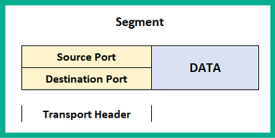
Figure 1.8 – Transport header information
Within the transport layer, there are two protocols that are responsible for the delivery of messages between a sender and a receiver over a network. These are the Transmission Control Protocol (TCP) and the User Datagram Protocol (UDP).
Transmission Control Protocol
TCP is often referred to as a connection-oriented protocol that guarantees the delivery of a message between a sender and a receiver. Before messages are exchanged between two devices, a TCP three-way handshake is established.
The following diagram shows the TCP three-way handshake process:

Figure 1.9 – TCP three-way handshake
The following is a live capture I took while using Wireshark. Look closely and you'll notice the sender, 172.16.17.14 (Client A), has sent a TCP Synchronization (SYN) packet to a destination address of 172.16.17.18 (Client B). By default, Client B responds with a TCP acknowledgement but additionally with a TCP SYN because it also wants to communicate with Client A. Hence, a TCP SYN/ACK packet gets returned. Finally, Client A receives the TCP SYN/ACK packet and responds with a TCP ACK to establish the TCP three-way handshake, as shown here:

Figure 1.10 – TCP three-way handshake shown in Wireshark
Once this process is complete, whenever each message is delivered to the recipient, a TCP ACK packet is sent back to the sender, indicating a successful delivery. However, if a sender does not receive a TCP ACK response from a recipient after a certain time, the sender will resend the message until a TCP ACK is received. This is how TCP ensures the delivery of messages on a network. However, due to the high overhead of TCP ACK packets on the network, not all application layer protocols uses TCP as their preferred choice of transport protocol. Some use UDP instead.
User Datagram Protocol
The UDP is a connectionless protocol, known for its best-effort delivery methods. Best-effort simply means the UDP protocol will send the message but will not provide reassurance during delivery. This means that if the message is lost during transmission, UDP will not attempt to resend it. Unlike TCP, it does not provide any message delivery guarantees. If an application layer protocol such as DNS uses UDP for transporting its messages, the transport layer will send it off to its intended destination without any prioritization or any reliability during the message's transmission on the network.
Unlike TCP, UDP does not provide any delivery confirmation, though some application layer protocols prefer UDP for its low overhead and speed on the network.
Layer 3 – Network layer
The network Layer, (Layer 3) is responsible for the logical address on the network and the encapsulation of the IP header, which adds both the source (sender) and destination (receiver) IP version 4 (IPv4) and/or Internet Protocol version 6 (IPv6) addresses to the packet.
This layer provides the following functions:
- Logical addressing of end devices
- Encapsulation and de-encapsulation of datagrams
- Routing (moving packets between networks)
The Internet Protocol (IP) operates at this layer. IP is a connectionless protocol, which means the protocol itself does not establish a session with a recipient before attempting to send or receive messages. In a similar way to the UDP of the upper layer (transport layer), it is also sent using best-effort mechanisms, thus providing no delivery guarantee for IP packets. Lastly, IP can function independently from the medium on the network (copper, fiber optic, or even wireless). Since IP does not have any reliability, the responsibility of ensuring packet delivery depends on the transport layer.
Furthermore, the network layer provides the functionality of directing traffic flows using routing protocols, which operate using the IP. At this layer, routers operate as they have the ability to read and understand IP addressing and the contents of a packet.
When the PDU is passed down to the network layer, it is encapsulated with an IPv4 or an IPv6 header to provide logical addressing, as shown here:

Figure 1.11 – Packet header
Keep in mind that the source and destination IP addresses do not change during their transmission between devices on a network. However, there is one exception: the source IP address changes when it passes a NAT-enabled router, which is configured to change a private IPv4 address into the public IPv4 address of the router's internet-facing interface. We will cover Network Address Translation (NAT) in Chapter 9, Configuring Network Address Translation (NAT).
At this state, the PDU is called a Packet. In later chapters, we'll discuss IPv4 and IPv6 in greater detail.
Layer 2 – Data link layer
The data link layer (Layer 2) of the OSI model is responsible for allowing the messages of the upper layers to access the physical network. It also controls how data is placed and received on the physical network (media), and it handles error detection and flow control. Within the data link layer, there are two sublayers. These are the Logical Link Control (LLC) and the Media Access Control (MAC).
Logical Link Control
LLC encapsulates the packet that's received from the network layer into a frame by adding a Layer 2 header containing the source (sender) and destination (receiver) MAC addresses. At the end of the frame, a trailer is added. The trailer of a frame contains the File Check Sequence (FCS). The data link layer creates a hash value to represent the contents of the frame; this is known as the Cyclic Redundancy Check (CRC) hash value. The CRC value is located in the FCS field of the trailer. The recipient device(s) use this value to determine whether the frame was corrupted or modified during its transmission between the sender and the receiver.
Media Access Control
For a device to connect and communicate on a computer network, a Network Interface Card (NIC) is required. The NIC allows the device to establish a connection to the physical network, regardless of whether the medium is copper or fiber optic cabling, or a wireless connection such as Wi-Fi. The NIC enables a device to exchange messages with another device while using the media (or medium) as the highway.
The MAC address is 48 bits (6 bytes) in length and is presented in the format of hexadecimal values; that is, 0 1 2 3 4 5 6 7 8 9 A B C D E F. An example of a MAC address is 12 : 34 : 56 : 78 : 9A : BC. The first 24 bits of the MAC address are known as the Organization Unique Identifier (OUI). The OUI identifies the manufacturer of the Network Interface Card (NIC) and the second 24 bits are assigned by the manufacturer. The MAC address is also known as a burned-in address (BIA) since it is hardcoded onto the hardware and, theoretically, can't be changed.
The following diagram represents a datagram known as the Frame. It contains both a Data Link Header and a Trailer:

Figure 1.12 – Frame header
Notice that an additional field inserted called the Preamble. The Preamble is a 7-byte field used on an Ethernet frame to indicate the start of the frame, its sequencing, and its synchronization. Before the data link layer places a message on the physical layer, it needs to break it up into smaller piece called bits. Each bit will contain the addressing headers, trailers, and the preamble, which contains a sequence for each bit.
The following diagram represents a depiction of two computers. PC A is sending some messages to PC B and since the blocks represent the message, it has been segmented into small bits. These are then sent across the network to the recipient:

Figure 1.13 – Bits moving across the physical layer
When the bits are received on the destination device, the sequence numbers of each bit will help the recipient reassemble the bits into a message.
To check the MAC address of your network adapters on a Microsoft Windows operating system, use the following instructions:
- On your Windows computer, use the keyboard combination Windows Key + R to open Run.
- Enter
cmdand click OK. - The Windows Command Prompt window will appear; enter
ipconfig /allto display the current settings of all the network adapters on your device.The following screenshot shows the output after running the
ipconfig /allcommand:

Figure 1.14 – MAC address on a Windows device
On Microsoft Windows, the Physical Address is the MAC address of the NIC.
Important note
On some operating systems, the MAC address is shown in XX:XX:XX:XX:XX:XX, XXXX.XXXX.XXXX, or XX-XX-XX-XX-XX-XX format.
Additionally, if you would like to determine the manufacturer of the device, use the following steps:
- Open your web browser and go to https://www.wireshark.org/tools/oui-lookup.html. You can enter the search term
mac vendor lookupto discover more OUI lookup websites on the internet. - Enter the MAC address of the NIC in the search field and start the search.
The following is the OUI search results:

Figure 1.15 – MAC vendor lookup
Now that you know about the data link layer, how to determine the MAC address, and how to perform a vendor lookup, let's take a look at the physical layer.
Layer 1 – Physical layer
The physical layer (Layer 1) is used to transport the messages that are created by the host device using network media. When messages are placed on the media, they are converted into signals such as electrical, light, and radio frequency, depending on the medium (copper, fiber, or wireless). At this layer, the PDU is known as bits.
Network components
In very network there is some form of media that's used to transport messages (signals) between devices. Ethernet is the underlying technology standard that describes how messages (signals) are transmitted over a cable at a defined speed. Ethernet is part of a family of communication standards developed by the Institute of Electrical and Electronic Engineers (IEEE).
Important note
Specifically, Ethernet is defined by IEEE 802.3.
Furthermore, Ethernet has standards for both copper and fiber optic cabling and supports speeds ranging from 10 Megabits per second (Mbps) to 10 Gigabits per second (Gbps). Keep in mind that these speeds may vary based on various variables, such as the length of the cable, the type of cable, and whether the signals are transmitted through copper or fiber.
There are two main types of cabling that are used on an Ethernet network: copper and fiber. In the following sections, we will outline the characteristics of each type and their use cases.
Copper cabling is very cheap and easy to implement in almost all environments. There are two popular types of copper cables: Unshielded Twisted Pair (UTP) and Shielded Twisted Pair (STP).
Important note
STP cables provide protection from electromagnetic interference (EMI) compared to the UTP cable. However, due to this added feature, the cost of STP cables is a bit higher because a metal shielding is used during the manufacturing process and this needs to be grounded.
Each of these cables contains a total of eight copper wires, each of which has their own color code, as follows:
- Green
- White and green
- Orange
- White and orange
- Blue
- White and blue
- Brown
- White and brown
With copper, there are a number of cable categories. The following are the characteristics of various cables:
- Cat 3: Contains two pairs of twisted wires and supports
10Mbps at a maximum distance of100meters - Cat 5: Contains four pairs of twisted wires and supports up to
100Mbps at a maximum distance of 100 meters. - Cat 5e: Contains four pairs of twisted wires and supports up to
1,000Mbps at a maximum distance of100meters. - Cat 6: Supports up to
10Gbps from up to37to55meters. - Cat 6a: Supports up to
10Gbps from up to100meters. - Cat 7: Supports up to
10Gbps from up to100meters.
Copper cables are all susceptible to attenuation. Attenuation is the loss of signal over a great distance. In the field of networking, when a device is sending a signal over the wire, the longer the distance the signal has to travel, the more likely the signal will deteriorate (get weaker) as it's moving along the wire.
Nowadays, ISPs are rolling out fiber-optic cables between their head offices and their customers' locations to provide increased bandwidth and other services. You may be wondering, what is fiber optic? Fiber uses light pulses to exchange messages in the form of bits. These light pluses are generated using light-emitting diodes (LEDs) rather than electrical signals used in the regular network cables we are accustomed to. Since fiber cables uses light pulses, this creates a major benefit for network and telecommunication professionals.
The core material a fiber cable is made with is either glass or plastic. The plastic core is cheaper to manufacture and therefore the fiber cable itself is cheaper to the customer. Additionally, it is less fragile compared to a cable with a glass core. The glass core allows for higher throughput due to its less dense material. Keep in mind that neither a glass or plastic core can be bent; both cores can be broken easily with very light force.
Fiber has some benefits; for example, much larger throughputs of network traffic can be supported, signals can travel along a fiber cable for many kilometers without experiencing signal loss, it's immune to EMI and RFI, and it allows service providers to transport more services and bandwidth to customers. However, there are a couple of disadvantages. The cost of fiber is a lot higher than the cost of copper cables because of the material composition. Also, the fragile nature of the fiber optic core (glass or plastic) makes the cable susceptible to damage.
Fiber optic cables can operate in two modes: single mode fiber and multi-mode fiber. The following are the characteristics of these two modes:
Single-mode fiber has the following characteristics:
- Small core
- Suited for long distances
- Uses laser as the light source
- Produces a single straight path for light
- Commonly used to interconnect cities
Multi-mode fiber has the following characteristics:
- Has a larger core
- Suited for long distance but shorter than single-mode fiber
- Uses LEDs as the light source
- Commonly used on LANs
- Allows multiple paths for light
With that, we have covered all the layers of the OSI reference model in detail. Now, let's take a look at the TCP/IP protocol with reference to each network layer.
Understanding the TCP/IP protocol suite
As mentioned in the earlier sections of this chapter, the TCP/IP was developed by the US Department of Defense and has been implemented in all networking devices since its approval. The protocol suite is currently maintained by the Internet Engineering Task Force (IETF).
Unlike the OSI reference model, the new updated TCP/IP protocol suite has five layers. The following diagram displays the five layers, along with their alignment to the OSI model:

Figure 1.16 – OSI model and TCP/IP protocol suite comparison
To compare, the upper layers of the OSI model (application, presentation, and session) are equivalent to the application layer (Layer 4) of the TCP/IP protocol suite. The transport layer of the OSI model remains the same for TCP/IP; however, the data link and physical layers are also equivalent to Layers 1 and 2 of the TCP/IP suite.
Keep in mind that TCP/IP has been implemented in all network-connected devices, ranging from end devices and smartphones to servers and network devices.
Understanding the functions of network devices
On almost every network, there are a range of different devices that can be found, each with a unique function and purpose. In this section, we will discuss the functions of various network components. At the end, you will understand the roles each network device plays to ensure we have end-to-end connectivity over a network.
In the following subsections, we will discuss the functions and features of a Hub, Switch, Router, Firewall, Intrusion Prevention System (IPS), Access Point (AP), Cisco-based network controllers such as Cisco DNA and Wireless LAN Controller (WLC), and endpoints and servers.
Hubs
In today's world, you won't really find too many Hubs on enterprise networks. Hubs are a very old type of network intermediary device, used to interconnect computers, servers, printers, and other end devices to create a network. However, Hubs are now obsolete and are no longer recommended to be used in any network.
Let's take a look at how Hubs operate on a small network. Firstly, Hubs are devices used strictly for repeating any incoming signals they may receive on any of their physical interfaces. To get a better understanding of how Hubs forward traffic on a network, take a look at the following diagram:
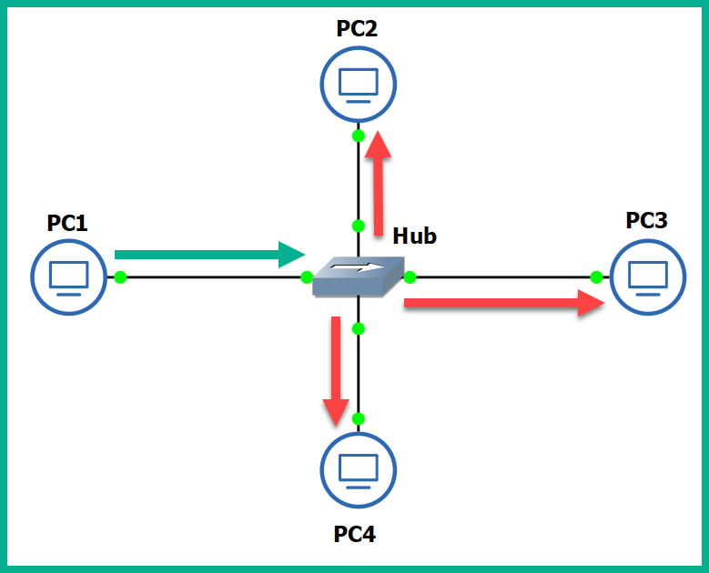
Figure 1.17 – Operations of a Hub
As shown in the preceding diagram, there are four computers connected to a unique physical interface (port) on the hub. In our scenario, PC1 wants to send a message to PC4. PC1 sends the message to the hub since it's the intermediary network device. The message is sent as an electrical signal along the network and to the hub. When the hub receives the signal, it rebroadcasts it out of all other ports, except the incoming port.
This means the message is also sent to unintended devices on the network, which is both a networking and security concern. First, let's understand the performance issues we can encounter if there are too many hubs as part of the network infrastructure. Any signal a hub receives is simply rebroadcasted out its other physical interfaces. Let's imagine there are multiple hubs being used on a single LAN for a building, where each hub is used to extend the physical network in order to interconnect all devices, such as network printers, desktop computers, and servers. Each time a device sends a message (signal) in a Hub's interface, it rebroadcasts it out of all the ports. This same signal will propagate to all the other interconnected hubs and do the same in the same manner, thus causing unnecessary broadcast (noise) traffic, which, in turn, will create network congestions. Think of it as a roadway being filled with too many vehicles, resulting in heavy traffic.
The following diagram shows the replication of the broadcast traffic through a small network:
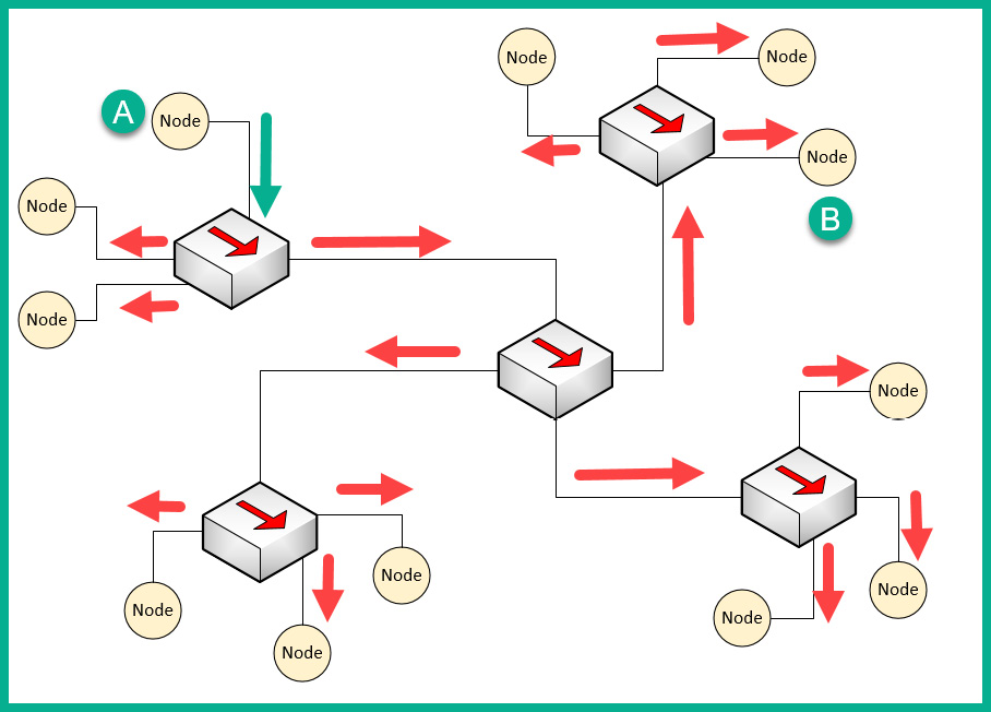
Figure 1.18 – Broadcast messages created by a Hub
Here, we can see that Node A sends a message to Node B but that the signal is being rebroadcast throughout the entire network.
What if you have two or more devices (nodes) transmitting messages at the same time over a Hub-based network? The result is the same as two vehicles colliding; in a network, this is known as packets colliding, which results in packets being corrupted. This means to ensure there is almost no collision, only one device should send their message at a time on the network. This creates a challenge because all the end devices on the network will be fighting to use the medium, thus creating a contention-based network.
To overcome such challenges, Carrier-Sense Multiple Access with Collision Detection (CSMA/CD) is used to help end devices such as computers to determine whether the media is clear (available) to transmit data (send a signal). Let's use a real-world analogy to explain how CSMA/CD works on a network. Imagine that, one day, you are shopping in the city and you want to visit various shops and stores. There are roadways separating them. Imagine the roadway is the media (wire) and you have to cross the road to reach the other store. Before crossing the road, you look both ways (left and right) a few times to ensure there are no vehicles (signals) passing and that it's safe to cross the street. Therefore, you are checking the media to ensure no vehicles (signals) are passing. When the media is clear, you proceed to walk across to the other side (transmit).
CSMA/CD ensures a device checks the media for a signal. If a signal is found on the media, the device waits and tries again at a later time. If the media is free, the device proceeds to transmit its message across the network.
However, network switches overcome this issue and devices do not have to check the media before transmitting their messages. In the next section, we will learn about the characteristics of switches.
Layer 2 switches
Switches are considered to be smart devices compared to hubs. Switches are devices that network professionals use to interconnect end devices (PCs, printers, servers, and so on) and extend the network infrastructure, typically extending a LAN within a building. As you may recall, in a hub, any incoming signal is rebroadcasted out all other ports. However, with a network switch, this is no longer the operational state. With a switch, when a device wants to send a message to another device, the switch directly forwards the message to the intended recipient.
The following diagram shows a small LAN where PC1 is transmitting a message to PC4 and the switch forwards the message only to PC4:
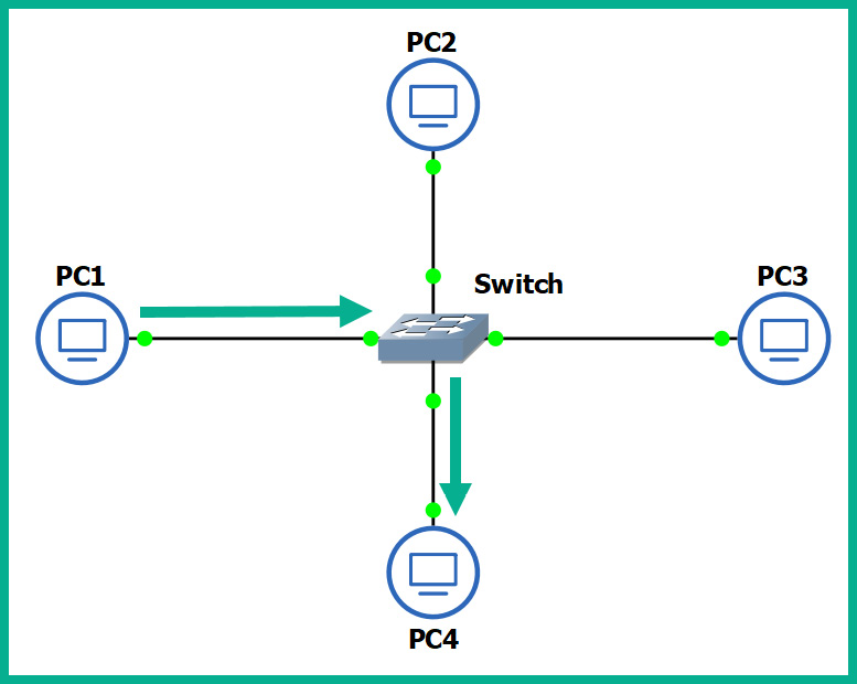
Figure 1.19 – Functions of a switch
You may be wondering, how is this possible? How does a switch defer from a hub? How does the switch determine which interface (port) the recipient is connected to? To put it simply, switches operate at the data link layer (Layer 2) of the OSI reference model. As you may recall, at the data link layer, the MAC addresses are inserted into the Layer 2 encapsulation header of the frame.
Switches are able to read the Layer 2 header information found in frames and create a table to temporarily store the MAC addresses it learned about on its interfaces. This table is known as the Content Addressable Memory (CAM) table in Cisco switches. Whenever a frame enters a switch's interface, the source MAC address of the frame is stored in the CAM table and is associated with the incoming interface.
To further understand how a switch populates the CAM table, let's imagine we have three PCs, all connected to a network switch to create a small LAN, as shown in the following diagram:
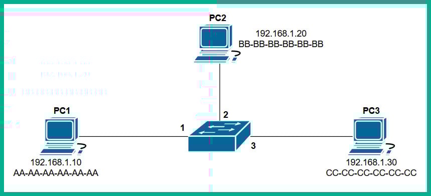
Figure 1.20 – Devices interconnected using a switch
Whenever a switch boots up, the CAM table is empty because its content is stored in Random Access Memory (RAM). Therefore, the content is lost whenever the device is powered off or rebooted. To begin, the CAM table is currently empty until end devices begin to exchange messages on the network.
Let's assume PC1 wants to send a message to PC3. Typically, we think both devices would use the IP addresses of each other to communicate on a local network, but this is not the case when it comes to working with network switches. Switches are only able to read the Layer 2 header of a frame, which contains source and destination MAC addresses, not IP addresses. There is no way for a network switch to read an IP header unless it's a Layer 3 switch; we will discuss Layer 3 switches in the next section.
PC1 knows the IP address of PC3 but not its MAC address. Therefore, PC1 sends an Address Resolution Protocol (ARP) request message on the network, requesting the IP address 192.168.1.30.
Important note
ARP is used to resolve IP addresses to MAC addresses on a network. Remember, for communication that happens on a local network, messages are exchanged via switches. This means each device uses MAC addresses to communicate with other devices on the same network.
The following diagram shows an ARP Request being sent through a network:
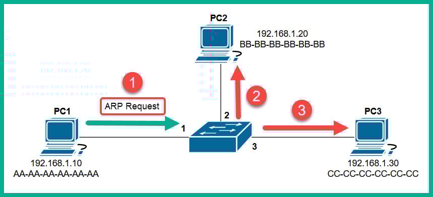
Figure 1.21 – ARP Request message
Each device on the LAN will receive the ARP Request message via a broadcast (all devices on the LAN receive the same message). At this point, the switch receives the ARP Request message on Interface 1 and populates the source MAC address on the CAM table, as shown here:
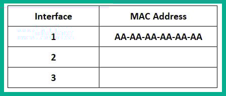
Figure 1.22 – CAM table
Only the device who has the IP address of 192.168.1.30 will respond with an ARP Reply, as shown here:
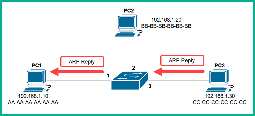
Figure 1.23 – ARP Reply
The ARP Reply message is a unicast transmission (device to device) and is sent directly to PC1. Keep in mind that the switch reads the frame header and populates the source MAC address into its CAM table, as shown here:
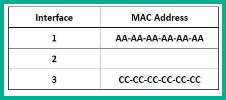
Figure 1.24 – CAM table
Additionally, the end devices also have their own ARP cache that temporarily records IP-to-MAC binding information. If there are no messages being exchanged between a MAC address for a predefined time interval, the operating system removes them from its ARP cache. On Cisco devices, the CAM table maintains a default inactivity timer of 300 seconds (5 minutes); this value can be modified.
Important note
To view the contents of the CAM table on a Cisco IOS switch, use the show mac address-table command.
To view the ARP cache on a Microsoft Windows operating system, follow these steps:
- Open the Command Prompt.
- Use the
arp –acommand and press Enter.The following snippet shows the ARP cache's contents on a Windows host computer on my network:
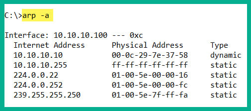
Figure 1.25 – ARP cache on a Windows machine
To view the ARP cache on a Linux operation system, use the following steps:
- Open the Terminal.
- Use the
arpcommand and press Enter.
The following snippet shows the ARP cache's contents on a Linux (Debian) host computer on my network:
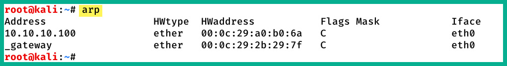
Figure 1.26 – ARP cache on a Linux machine
In both snippets, we can see that the ARP cache contains both IP-to-MAC address bindings of the other devices that exchanged messages.
Now that we have an understanding of how Layer 2 switches function, let's take a look at Layer 3 switches.
Layer 3 switches
Layer 3 switches have all the same functionalities as the Layer 2 switches. However, these devices come with an additional feature. They can read the information within an IP packet header, as well as the source and destination IP addresses. This enables the Layer 3 switch to interconnect two or more networks together and allows basic routing of IP packets between networks.
Keep in mind that Layer 3 switches do not have all the features of a Cisco router. In the next section, you will learn about the features and characteristics of a Cisco router.
Routers
A router is a device that is used to interconnect two or more different IP networks. These devices observe the destination IP address within the header of an IP packet, then check its local routing table for an available path to the destination's network when making its decision to forward the packet to the recipient.
Since routers can read and understand IP. They are considered to be Layer 3 devices due to their capabilities of reading IP information from packets. Without routers, end devices would not be able to communicate with devices residing on another IP network. The following diagram shows two IP networks, 192.168.1.0/24 and 172.16.1.0/16. Devices on the 192.168.1.0/24 network will only be able to intercommunicate between themselves; the same goes for the devices on the 172.16.1.0/24 network:
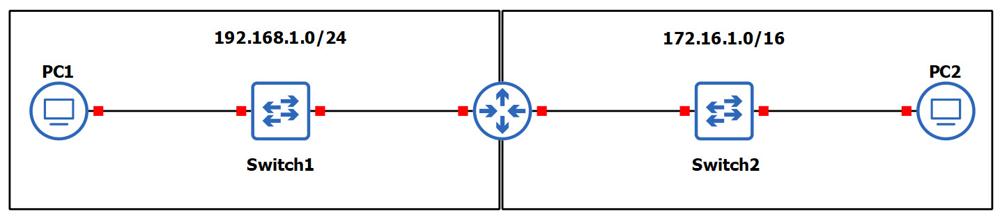
Figure 1.27 – Router interconnecting different networks
To allow both networks to exchange messages, a Layer 3 device such as a router is required. The router is used to interconnect these two different networks together. Additionally, the router acts at the default gateway for each of the networks. This means that if PC1 wants to send a message to PC2, the message must be sent to the doorway that leads to another network. This is the router in this scenario.
As a real-world example, your network at home is a private network and uses technologies a bit differently than those that are used on the ISP network and the internet. The following diagram shows a home network that is connected to the internet:
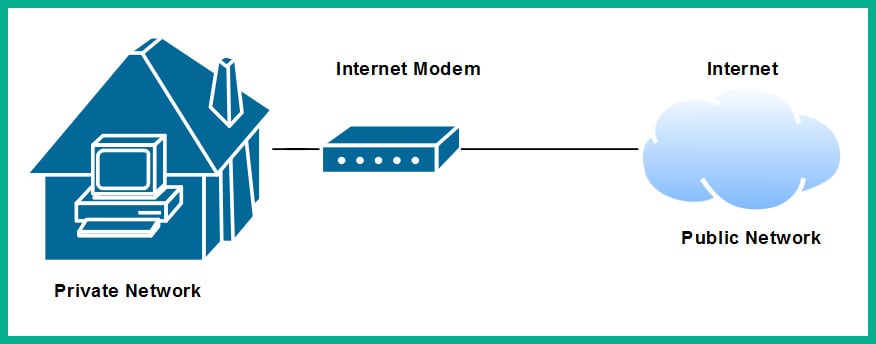
Figure 1.28 – Internet connection to a house
The private network uses a very different address space than what is used on the internet (public network). To allow communication between these networks, the ISP provides you with a modem, which has the capabilities of a router. This allows the ISP network to interconnect to your home (private) network. Lastly, the modem in this scenario acts as the default gateway for all your devices, providing a path to the internet.
Now that you have learned about the fundamentals of routers, let's cover the importance of implementing a firewall on an enterprise network.
Next-generation firewalls and IPS
A firewall is a network security appliance that is designed to filter malicious traffic, both inbound (entering a network) and outbound (leaving a network). Firewalls have an important role to play in networks of different sizes. These appliances typically sit at the network perimeter of an enterprise network, carefully inspecting all incoming and outgoing traffic, looking for any security threats and blocking them.
To get a better understanding of the benefits of using a firewall, let's use a simple analogy. A vehicle such as a car has a physical component called a firewall, which is the place between the cabin and the engine. The purpose of this component is important in the event of the engine of the car catching fire; the firewall will prevent most (if not all) the fire or heat from entering the cabin where the passengers are seated. Another analogy is a castle being surrounded by a moat and a single drawbridge that provides people with a single entry and exit point. In the event an opposing side wants to invade the castle, the drawbridge can be raised, and the moat will prevent the enemy from entering.
It is highly recommended to implement a firewall on your network. The internet contains millions of useful resources, from training videos to cooking recipes. However, there are many threats, such as malware and hackers, that roam the internet and attempt to infect and compromise systems. The firewall will act as the first line of defense against these threats.
The following diagram shows the typical deployment of a firewall on a network:
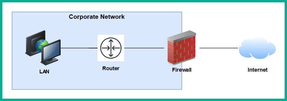
Figure 1.29 – Perimeter firewall deployment
Next-generation firewalls (NGFW) are designed to be superior in many ways, such as protecting the network and users from advanced threats, providing Deep Packet Inspection (DPI), preventing ransomware from entering the network, and having Virtual Private Network (VPN) features.
A firewall, by default, will allow traffic originating from the internal private network to go to all other networks, such as the internet. However, any traffic that is initiated from the internet to the internal corporate network is blocked by default. The firewall uses the concept of a security zone to help determine the level of trust it has for a logical network. When deploying a firewall, the security engineer must configure the interfaces of the firewall as a security zone with a trust level.
The following diagram shows the default security level for a Cisco Adaptive Security Appliance (ASA) firewall:
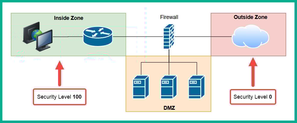
Figure 1.30 – Security zones of a firewall
The Inside Zone is usually your private, internal network, which is supposed to be a fully trusted and safe environment for all devices in the corporate network. This zone will normally hold a security level of 100 to indicate it's a fully trusted security zone. The firewall will allow all traffic originating from the Inside Zone with a security level of 100 to all other zones that have lower security levels. The internet as we know it is the most unsafe network in existence, being filled with extremely malicious malware and hackers, so the internet is usually assigned a security level of 0 as a Zero Trust zone. Any traffic that has been initialized from the internet to the Inside Zone will be blocked by default on the firewall. However, keep in mind that if a user on the Inside Zone has initialized a connection to the Outside Zone, the firewall will allow it by default, and if there is any returning traffic, the firewall will allow it as well. For example, as you open a web browser to visit www.google.com, the firewall will allow the HTTP GET message to the web server, and then the web server will send a response back the user's computer. In this case, the firewall will only allow the returning traffic.
Important note
Please note that the security-level schemes mentioned in this book are based on the Cisco technologies.
The Demilitarized Zone (DMZ) is a semi-trusted zone that's attached to the firewall on the corporate network. This zone is created to place servers that are accessible from the internet and the Inside Zone. The following are some guidelines for creating a DMZ on your network:
- The traffic initiating from the DMZ should not be allowed to access the Inside Zone.
- Rules should be created on the firewall to allow specific traffic to flow to the servers within the DMZ only. If there is a web server, then incoming HTTP and HTTPS traffic should be sent only to the web server.
- Ensure traffic initiating from the Inside Zone can access the DMZ.
Lastly, the security level of the DMZ should be between the value of the Inside and Outside Zones. However, within an organization, there many multiple trusted zones that have a security level closer to 100. There may be additional trusted zones, so the DMZ should have a security level of 50.
Intrusion Prevention Systems
An Intrusion Prevention System (IPS) is a component that is used to detect and block malicious traffic. In a traditional deployment, the IPS appliance usually sits in line of all incoming traffic and behind the firewall on the network. This type of deployment ensures the IPS can inspect all traffic as it passes through the appliance.
The following diagram shows the traditional IPS deployment model on a network:
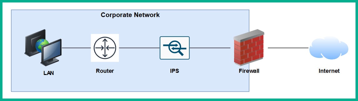
Figure 1.31 – Traditional IPS deployment
Traditional IPS appliances are deployed behind the firewall within the corporate network. Their purpose is to inspect any traffic and catch both suspicious and malicious traffic the firewall may have missed. Years ago, the IPS appliance was a separate physical device. However, with the advancement of technologies and innovation, Cisco has integrated the IPS into their next-generation firewall appliances as a module. The benefits of this are a less physical appliance and a firewall interface that provides a single management dashboard for both the Cisco IPS and firewall all-in-one appliance. This allows a firewall administrator to enable the IPS feature with the use of a license key provided by Cisco systems.
Next-generation IPS (NGIPS) inspects and filters traffic a bit differently to a firewall. The IPS downloads a database of malware signatures from TALOS, Cisco's Security Intelligence and Research Group. It uses this information to closely inspect all traffic flowing through it to identify any malicious traffic. Additionally, the IPS can be manually configured with predefined rules created by a security engineer. It can also automatically learn the behavior of the network to catch abnormal traffic types. The awesome benefit of having an IPS on a network is that if it detects any malicious traffic, it can stop it in real-time, preventing the attack.
Tip
If you're interested in building your own IPS device, check out Snort at www.snort.org. Snort is an open source intrusion prevention system application.
On the other hand, IDSes are considered to be reactive devices compared to IPSes. An IDS is configured to receive a copy of the network traffic, detect security threats, and send alerts. IDSes are not implemented in-line with network traffic, so they do not have the capability to stop an attack as it happens on a network. Furthermore, the IDS only sends an alert after an attack has happened, which makes it reactive in nature.
Now that we have learned about the functions of firewalls and IPSes, let's take a look at a device that allows us to extend a wired network into a wireless one.
Access Points
An Access Point (AP) is a device that allows you to extend a wired network into a wireless frequency, allowing wireless-compatible devices to connect and access the resources on the wired network.
This provides many benefits, such as the following:
- Increases the mobility of users and roaming within a compound
- Reduces the need for physical cabling
- Increases ease access to a network
Wireless APs use a wireless radio frequency, which is broadcast from the AP using the 2.4 GHz and/or 5 GHz channels. This allows mobile devices with a compatible wireless NIC to listen on these frequencies and connect to an AP. Most commonly, the 2.4 GHz APs are found almost on every wireless network due to the fact it was the first type of AP produced and a lot of organizations and home users invested in the technology.
Important note
The 2.4 GHz channel provides a lower frequency and gives a greater distance.
As there are so many building and homes equipped with a 2.4 GHz AP, the radio airways of 2.4 GHz are now a very saturated space, where each device is trying to transmit their data to clients without causing interference. This has become almost impossible now. The 2.4 GHz band uses a total of 11 channels; however, it is recommended to use channels 1, 6, and 11 to ensure there is no overlapping.
The following diagram shows the recommended clean channels of the 2.4 GHz channels:
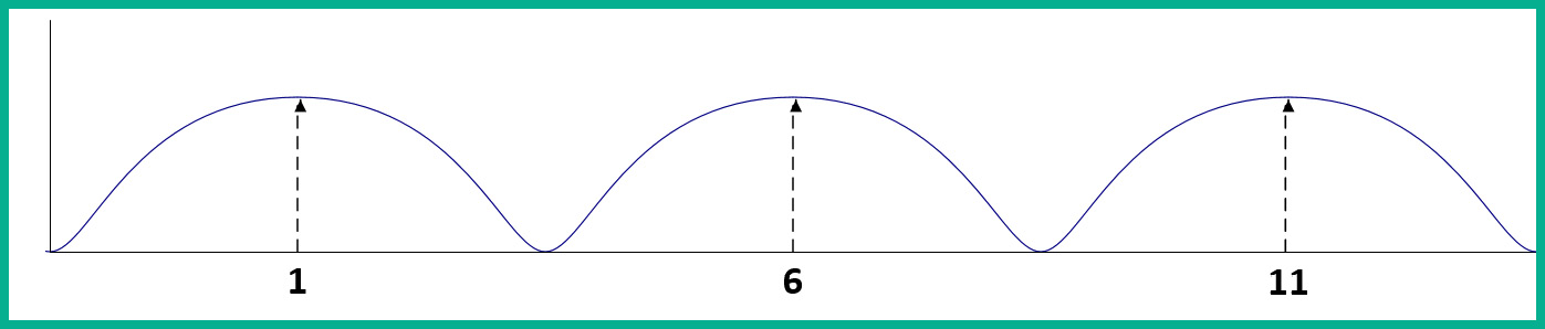
Figure 1.32 – Wireless channels range
However, even this recommendation is no longer beneficial. An AP can be using channel 2, 4, or even 8, which will create an overlap (interference) between the recommend channels (1, 6, and 11).
The 5 GHz frequency provides a lot more channels, thus creating less interference among nearby Access Points that are operating on the 5 GHz frequency. The downside of using 5 GHz is the short distance the signal can travel. However, this may be a benefit. Let's imagine that a company with multiple floors in their building are deploying the 5 GHz frequency Access Points; because the 5 GHz frequency travels much shorter distances, this means the possibility for one AP's signal to interfere (overlap) with another AP who is using the same frequency has been reduced.
Important note
In later chapters of this book, we will discuss wireless architectures in more depth.
Having covered the purpose of using Access Points, let's take our discussion a bit further and describe how to improve the management of our corporate wireless network.
Cisco Wireless LAN Controller (WLC)
Wireless LAN (WLAN) is simply defined as a wireless network containing either a single Access Point at home for personal use or an organization containing multiple Access Points to provide wireless connectivity between employees' mobile devices (smartphones, tablets, and laptops) and the wired network infrastructure. With the increase of wireless networking, a lot of companies are implementing a Bring-Your-Own-Device (BYOD) policy to ensure an acceptable level of security is established and maintained. However, for network engineers, this means the wireless network needs to be able to support the large number of portable devices that are connecting and exchanging messages on the WLAN.
This will result in network professionals having to implement a robust wireless network with multiple APs throughout the organization, on each floor and room where a wireless signal is needed or required. Let's imagine that our fictional company, ACME Corp, own a 10-storey building and that the network administrators have to implement Access Points. One key aspect is to maintain the consistency of each AP's firmware, configurations, and security settings. Imagine that, after the deployment of the wireless network, the network administrator has to make a change on the WLAN that will affect all Access Points. It's definitely not efficient to log into each Access Point and manually make the changes in the device's configuration as this is time-consuming and prone to human error.
A WLC allows a single management interface for the entire wireless network. This device enables you to control any number of APs on a network. Therefore, you can simply log into a WLC and configure the entire WLAN, providing a centralized management platform for network professionals. In later chapters, we will cover various deployment models for Access Points and wireless LAN controllers in more detail.
Endpoints and servers
So far, we have been talking about intermediary devices that connect us to a network and the internet. However, we must not forget about the simple yet cool devices that allow us to communicate on a network and provide resources to others: endpoints and servers.
Servers are devices that run specialized applications that enable them to provide resources to users on a network. To get a better idea of the functionality of a server, let's imagine you work for a small business with approximately 30 employees, all residing in a single building. Each employee has their own company-issued laptop or desktop computer fitted with all the relevant software applications for each person to complete their duties efficiently. Each day, employees may be creating new documents and files that have to be shared with others in the organization; however, emailing each file to a user or group may not always be the best way to efficiently collaborate on a project.
In this case, a centralized file server can be set up within the company's network to allow various persons or all employees to centrally store their work-related files on the file server, rather than storing them locally on their computers (endpoints). In this scenario, the server is hosting files for the organization or the client (endpoint) devices to access.
Keep in mind that client devices (endpoints) are usually devices that are connected to a network to access a resource. These might be laptops, smartphones, tablet computers, desktop computers, and so on.
Cisco DNA
The Cisco Digital Network Architecture (DNA) is an IP-based software solution designed by Cisco Systems to provide engineers with applications they can use to manage, automate, and gather intelligence analytics, as well as monitor security, on a Cisco network across multiple devices and platforms.
Network topology architectures
One of the tasks you may have to perform as a network engineer is to design an optimal network for a customer. How do we get started with planning and designing a network? To get started with such a task, you need to determine some important key details about the customer's needs. The following are some key guidelines to help you plan your network:
- Meet with the customer to determine their needs and expectations.
- Understand the budget the customer has planned for the solution.
- Ensure your team has the right skillset and certified professionals to work on the project.
- Determine the type and quantity of the networking devices required for the implementation.
Important note
Please note that these are just a few typical questions; your planning phase should not be limited to the points mentioned here.
The first point is very important. As a professional in the field, you do not want to assume anything about the customer's needs. Ensure you have a proper discussion and take note of exactly what the customer needs and their expectations. If you think the service or solution should be added on to what the customer needs, suggest it to the customer, providing its pros and cons, and gather their feedback.
Ensure you understand the budget for the project before choosing the type or quantity of network equipment to purchase. To determine the right device(s) to purchase, use the following steps as a guide:
- Go to Cisco's website at www.cisco.com.
- Navigate to Products | Networking. Here, you will see subcategories such as Switches, Wireless, Routers, and so on.
- Select Switches. Under Products, you will see that Cisco has made it simple for us to determine the type of network switch based on its purpose on a network. You'll see that there are network switches for LAN Access, Distribution and Core switches, Data Center, and even Small-business switches.
- Click on Catalyst 1000 Series. When the new page loads up, click on Models. Here, you will see an overall description of each model belonging to the Catalyst 1000 line of products. However, your research does not stop here.
- Scroll down until you see the Resource section. You will see the Data Sheet for the models; click on it. The Data Sheet provides the exact specifications for a variety of devices within the product family. It provides the type and number of physical interfaces, unlink capacity, bandwidth capacity, and the physical dimensions and weight of the device.
Using the same concept, other devices such as wireless, routers, and firewalls will be very useful as you determine the right model of device(s) needed for the deployment of a project.
You may be wondering, what about the actual network design? Do we design all networks from the ground up? What makes our network design optimal? To answer all these questions, the experts at Cisco Systems have created a Design Zone containing tons of Design Guides. These are known as Cisco Validated Design (CVD) guides.
Important note
Cisco Validated Design can be found at https://www.cisco.com/c/en/us/solutions/design-zone.html.
Keep in mind that there is a CVD for almost every type of network and deployment for various type of industries. These design guides will provide you with guidance, recommended devices, design models, and full descriptions of their solutions. Such design guides eliminate the need to reinvent the wheel when there are experts who have already created both approved and accredited designs.
Cisco has created both a 2 Tier and 3 Tier network architecture, which is recommended for enterprise networks. In the following sections, we will discuss each of these architectures in greater detail.
2 Tier
When designing a LAN for a building or an organization that has multiple buildings near each other, we are indeed designing a campus LAN. Within a campus LAN, there are multiple network switches that are all interconnected. Sometimes, in the industry, you may see network switches interconnected in a fashion of chaining one switch to another. This is referred to as daisy chain or daisy chaining.
The following diagram shows multiple switches in a daisy chain model:

Figure 1.33 – Daisy chaining
For IT professionals, this may be a workable approach to extend their local area networks within a building. However, a major disadvantage to using such a design is that there is no redundancy in the event a cable or device fails. A fault cable or switch within the daisy chain can cause a disruption in network operations, which will affect all the devices that are connected to the faulty segment. Hence, such practices are not recommended when designing a campus LAN.
When designing a network, ensure it is hierarchical when creating various tiers to help you understand the roles of each device in the network. Ensure that the design is modular and improves the network's scalability, allowing you to expand the network and its services easily. Consider implementing resiliency and flexibility to ensure the user has a great experience while they execute their daily tasks in the organization. In other words, you don't want your users to experience a network failure that will disrupt daily transactions. Lastly, flexibility will ensure traffic is distributed between paths and devices efficiently.
Important note
In Section 5, Security Fundamentals, we will cover various security topics and techniques we can use to improve the security posture of a Cisco network.
This is where the Cisco 2 Tier architecture comes in to save the day when designing a LAN for a building – a campus LAN. This design creates two layers of switches: the distribution layer and the access layer.
The access layer provides a means of connecting end devices (computers, servers, printers, and so on) to the network. At the access layer, there is no form of redundancy between the end device and the access layer switch; this is due to most end devices usually having only a single NIC for LAN connectivity. However, each access layer switch is connected to two or more distribution layer switches, thus providing redundancy to the remainder of the network.
Tip
To see the Cisco Access layer switches, please visit the following URL: https://www.cisco.com/c/en/us/products/switches/campus-lan-switches-access/index.html.
The following diagram shows the Cisco 2 Tier architecture within a building (campus LAN):

Figure 1.34 – Cisco 2 Tier architecture
In a Cisco 2 Tier architecture, the distribution layer is known as the Collapsed Core. The distribution layer is responsible for the following roles and functions on a campus LAN:
- Providing Quality of Service (QoS) to prioritize network traffic
- Access Control Lists (ACLs) to filter network traffic
- Basic routing functions
The distribution layer also provides redundancy for interconnecting multiple access layer switches to expand the campus LAN.
Tip
To find out more about the Cisco distribution layer switch, please visit the following URL: https://www.cisco.com/c/en/us/products/switches/campus-lan-switches-core-distribution/index.html.
Keep in mind that the Cisco 2 Tier architecture is typically used within a building. This brings about the question, how do we interconnect multiple buildings that each have a Cisco 2 Tier architecture? One method is to simply interconnect the distribution switches of one building with another.
The following diagram shows multiple branches interconnected using the 2 Tier model:

Figure 1.35 – Multiple campus LANs
As you may have noticed, each distribution layer switch is connected to each other distribution layer switch in each of the campus LANs. As the network grows and more branch offices (campus LANs) are created, there will be too many inter-branch connections and the design will not be efficient.
To solve this issue, Cisco have designed a 3 Tier hierarchical model.
3 Tier
In the Cisco 3 Tier architecture, there are three layers. There is now a core layer. The core layer is defined as the high-speed backbone of the network. These core layer switches are used to forward traffic as quickly as possible between networks, which are geographically separated. To put this simply, the core layer switches are used to interconnect each campus LAN to the others in a more efficient way.
The following diagram shows a simplified version the Cisco 3 Tier model:

Figure 1.36 – Cisco 3 Tier architecture
The core layer plays a vital role in an enterprise network. To get a better idea of how the connections are made in a real-world scenario, let's take a look at the following diagram:

Figure 1.37 – Cisco 3 Tier architecture interconnecting multiple branches
As you can see, there are three campus LANs (branches). Each campus LAN has its own access layer switches that allows end devices to access the network. There is the distribution layer, which provides redundancy to the access layer, via multiple paths to each end device.
Important note
In the 2 Tier architecture, the collapsed core plays the role of both the distribution and core layers as one.
The core layer ensures each campus LAN (branch) is interconnected. If a branch has to send network traffic to another branch office, the traffic goes up to the distribution layer and then to the core layer for forwarding. Additionally, the core layer connects to the routers of the enterprise network. These routers provide internet and WAN connectivity.
The Cisco 3 Tier hierarchy has the following benefits:
- Improves network performance
- Improves the scalability of the network
- Creates better redundancy between paths
- Improves network management
The following is a summary of the functions and characteristics of each layer of the Cisco 3 Tier model:
- The core layer is the high-speed backbone of the network. These switches are used to forward traffic as quickly as possible between networks, which are geographically separated.
- The distribution layer is responsible for providing a boundary by implementing access control lists and other types of application filters and policies. The distribution layer is made up of Layer 3 switches.
- The access layer is used to interconnect end devices such as computers, printers, and servers.
Having completed this section, you are now able to identify the functions and purposes of each layer of both the Cisco 2 Tier (collapsed core) and 3 Tier architectures.
Summary
In this chapter, we learned about the evolution of networking and how the internet came into existence. Then, we learned about two important protocol models: the OSI reference model and the TCP/IP protocol suite. However, only TCP/IP is implemented on devices, which allows messages to be exchanged across a network. Furthermore, we looked at the roles and functions of various networking components and how they forward messages between devices. Lastly, we covered the essentials of the Cisco 2 Tier and 3 Tier architectures in detail to help you understand how to design a campus LAN for an organization.
I hope this chapter has been informative for you and that it will be helpful in your journey toward learning how to implement and administrate Cisco solutions and preparing for the CCNA 200-301 certification. In the next chapter, Getting Started with Cisco IOS Devices, we will learn how to access and configure Cisco IOS devices while building a small network.
Questions
Here's a short list of review questions to help reinforce your learning and help you identify gaps in your knowledge:
- Which layer of the OSI reference model is responsible for encapsulating the physical address of a device?
A. Internet
B. Data link
C. Network
D. Link
- An employee uses Microsoft Outlook on their client PC to send and receive emails to/from others. Which is the highest layer of the OSI model?
A. Presentation
B. Internet
C. Session
D. Application
- The physical address of a device is made up of how many bits?
A.
32B.
42C.
48D.
52 - Which layer of the TCP/IP protocol suite is responsible for computing the checksum (hash) and determining whether a frame is damaged?
A. Network access
B. Data link
C. Physical
D. LLC
- In which layer of the TCP/IP protocol suite does routing occur?
A. Network
B. Internet
C. Router
D. Data link
- What does a Cisco switch use to make the decision to forward a message across a network?
A. Destination IP address
B. Destination MAC address
C. Source MAC address
D. Source IP address
- Which network protocol is used to resolve the MAC address to the IP address of a host on the same local area network?
A. ARP
B. HTTP
C. TCP
D. UDP
- Which device is used to extend a network to another room or floor of a building?
A. Router
B. Firewall
C. Switch
D. Hub
- Where does a Cisco switch store MAC addresses?
A. RAM
B. HDD
C. ROM
D. CAM
- Which layer of the Cisco Campus LAN architecture is responsible for interconnecting different branch offices?
A. Router
B. Core
C. Distribution
D. Access
E. All of the above
Further reading
The following links are recommended for additional reading:
- TCP/IP overview: https://www.cisco.com/E-Learning/bulk/public/tac/cim/cib/using_cisco_ios_software/linked/tcpip.htm
- Cisco 3 Tier architecture: https://www.cisco.com/c/en/us/td/docs/solutions/Enterprise/Campus/campover.html
- Understanding network port numbers: https://hub.packtpub.com/understanding-network-port-numbers-tcp-udp-and-icmp-on-an-operating-system/