


In this chapter, we will cover the following topics:
What is Site Recovery Manager (SRM)?
Laying the groundwork for an SRM environment
Host presentation (Zoning) at the protected and recovery sites
Installing SRM on both the protected and recovery sites
Pairing SRM sites
Installing the Storage Replication Adapters
Adding array managers and enabling array pairs
Configuring placeholder datastores
Creating resource, folder, and network mappings
Virtual machine swap file location
With today's IT infrastructures, be it virtual or physical, disaster recovery is of prime importance. Any business should be able to continue operating with reduced downtime for its sustainability among the competition. It also has a legal obligation toward customers to whom it sold its services. Two of the major factors used to market or sell a service are its High Availability and Recoverability.
Recoverability is the guarantee that the service offered and its data are protected against failures, and High Availability is the guarantee that the service offered would remain operational and the failures are handled in a way that the user of the service would not even know that there was a failure.
There are many ways in which businesses plan and implement disaster recovery. Although important, much of these decisions depend on the budgetary constraints. What turns out to be the most important is the existence of a disaster recovery plan. Gone are those days when you had to wait for a long period of time before all your critical applications were made available at a recovery site. With a lot of automation and scripting, businesses now expect better Recovery Point Objective (RPO) and Recovery Time Objective (RTO).
RPO defines the amount of data an organization can afford to lose when measured against time.
RTO defines the amount of downtime the organization can afford for its services before it becomes operational again.
Both RPO and RTO are defined by time. For example, an organization can have an RPO set to 4 hours and RTO set to 1 hour. This means, it can afford to lose up to 4 hours of data, but it can only afford a service downtime up to 1 hour.
RTO only defines the amount of time a service can remain unavailable but doesn't account for the data loss. This is where RPO pitches in. It defines how much data loss can be afforded.
For example, if you were a company hosting an online document format conversion service, then setting a lower RTO value is very important because the customers will prefer access to the service, rather than to the historical data. The RPO value will determine how much historical data you will have to keep.
Both RPO and RTO help an organization to determine the type of backup and disaster recovery solution to meet the business requirements.
vCenter Site Recovery Manager (SRM) is an orchestration software that is used to automate disaster recovery testing and failover. It can be configured to leverage either vSphere replication or a supported array-based replication. With SRM, you can create protection groups and run recovery plans against them. These recovery plans can then be used to test the Disaster Recovery (DR) setup, perform a planned failover, or be initiated during a DR. SRM is a not a product that performs an automatic failover, which means there is no intelligence built into SRM that would detect a disaster/outage and cause failover of the virtual machines (VMs). The DR process should be manually initiated. Hence, it is not a high-availability solution either, but purely a tool that orchestrates a recovery plan.
vCenter SRM is not a tool that works on its own. It needs to communicate with other components in your vSphere environment. I will walk you through all the components involved in an environment protected by SRM.
The following are the components that will be involved in an SRM-protected environment:

SRM requires both the protected and the recovery sites to be managed by separate instances of vCenter Server. It also requires an SRM Instance at both the sites. SRM now uses PSC as an intermediary to fetch vCenter information.
The following are the possible multiple topologies:

As mentioned previously, SRM cannot work on its own. This is because it is only an orchestration tool and does not include a replication engine. However, it can leverage either a supported array-based replication or VMware's proprietary replication engine, vSphere Replication. We have separate chapters covering vSphere Replication.
Each SRM instance needs to be configured with an array manager for it to communicate with the storage array. The array manager will detect the storage array using the information you supply to connect to the array. Before adding add an array manager, you will need to install an array specific Storage Replication Adapter (SRA). This is because the array manager uses the installed SRA to collect the replication information from the array:

The SRA is a storage vendor provided component that makes SRM aware of the array's replication configuration at the array. SRM leverages the SRA's ability to gather information regarding the replicated volumes and direction of the replication from the array.
SRM also uses the SRA for the following functions:
Test Failover
Recovery
Reprotect

We will learn more about these functions in the next chapter. For now, it is important to understand that SRM requires an SRA to be installed for all of its functions leveraging array-based replication.
When all these components are put together, a site protected by SRM would look as depicted in the following figure:

SRM conceptually assumes that both the protected and the recovery sites are separate, regardless of their geographical location. But such a separation is not mandatory. You can use SRM to protect a chassis of servers and have another chassis in the same data center as the recovery site. Now that we have a brief understanding of the SRM architecture, it is time to learn how to setup these components.
You will need to perform a set of configuration activities to lay the groundwork for an SRM environment so that it can be used to test or execute the recovery plans.
Here is an outline of the tasks that need to be done to form an SRM environment:
Preparing the storage for array-based replication
Host presentation (zoning) at the protected and recovery sites
Installing SRM on both the protected and recovery sites
Pairing the SRM instances
Installing the SRA
Adding the array managers
Enabling the array pairs
Creating resource, folder, and network mappings
Creating placeholder datastores
The first thing that you will need to do is to make sure that your array is supported by VMware and licensed for array replication by the array vendor. Array Replication is a licensed feature from the storage vendor.
Now, to enable replication, you have a couple of approaches that you can employ:
|
Approach-1 |
|
|
Approach-2 |
|
Approach-1: This is used in scenarios where the array does not have the spare capacity to provision a separate LUN for host-protected VMs. This approach adds an administrative overhead if the VMs are spread across multiple datastores. It also contributes to the wastage of replication bandwidth and storage space, since the LUNs that are replicated will also contain unprotected VM data.
Approach-2: This is used in scenarios where you have ample spare capacity. This approach is the best as it reduces the complexity and avoids the wastage of replication bandwidth and space, unlike Approach-1. However, this approach will have an impact on the size of the LUNs required at both the protected and replication sites.
If you are involved in a new implementation, then you will have to plan how the ESXi hosts are zoned to the array at both the protected and recovery sites. This means that LUNs should be correctly zoned at the Fabric:
At the protected site array, zone the ESXi hosts to communicate with the array, and make sure that the LUNs housing the VMs to be protected are assigned to the ESXi hosts
At the recovery site array, zone the ESXi hosts to the array, but do not map the replica LUNs to the hosts yet
VCenter SRM has to be installed at the both the protected and recovery sites for the disaster recovery setup to work. The installation process is identical regardless of the site it is being installed at; the only difference is that at each site, you will be registering SRM installation to the vCenter Server managing that site.
SRM can be installed either on the same machine that has vCenter Server installed or on a different machine. The decision to choose one of the installation models depends on how you want to size or separate the service-providing machines in your infrastructure. The most common deployment model is to have both vCenter and SRM on the same machine. The rationale behind this is that SRM will not work in standalone mode, that is, if your vCenter Server goes down, there is no way to access SRM. Like vCenter Server, SRM can be installed either on a physical or on a virtual machine.
Another factor that you would want to take into account is the installation of the SRA. SRAs have to be installed on the same machine where you have SRM installed. Some SRAs would need a reboot after they are installed. So, it is important to read through the storage vendor's documentation prior to proceeding to make a deployment choice for SRM. If the vCenter downtime is not feasible, then you will have to consider installing SRM on a separate machine.
Nevertheless, it is important to make yourselves aware of the software and hardware requirements of a software installation before it is actually installed. This is to make sure that you don't run into compatibility or supportability issues during the course of using the product. To understand the requirements for SRM, refer to page 13 of the Site Recovery Manager System Requirements chapter, in the Site Recovery Manager Installation and Configuration guide for SRM 6.1.
This guide can be accessed at the following URL:
http://pubs.vmware.com/srm-61/topic/com.vmware.ICbase/PDF/srm-install-config-6-1.pdf
The following flowchart depicts the processes involved in installing vCenter SRM:

Let's assume that the SRM database and the 64-bit DSN have already been created. We will delve directly into the installation procedure using the SRM installer.
Before you begin, you will need to download the SRM installation bundle from VMware's website. It can be downloaded by navigating to www.vmware.com and then to Downloads | vCenter Site Recovery Manager. You will need to log in to your my.vmware.com account before you cloud download the executable.
The following procedure will guide you through the SRM installation wizard:
Double-click the downloaded executable to load the installer.
On the welcome screen of the installation wizard, click on Next to continue.
On the VMware Patents screen, click on Next to continue.
Accept the license agreement and click on Next to continue.
On the Installation Prerequisites screen, click on Next to continue.
Choose a destination folder for the installer to put the files. The default location is
c:\Program Files\VMware\VMware vCenter Site Recovery Manager\. You can change this by clicking on the Change button. For now, I have chosen to leave the default in place. Click on Next to continue.On the vSphere Platform Services Controller screen, supply the FQDN or the IP address of the PSC and its Single Sign-On (SSO) credentials:

The details supplied here correspond to the PSC of the vCenter site that you intended to protect. Click on Next to continue.
You will be prompted to accept the PSC certificate. Click on Accept and then on OK to close the Certificate Information window.
On the VMware vCenter Server screen, choose the vCenter to register the SRM instance with and click on Next to continue:

You might get a list of more than one vCenter if there is more than one vCenter using the same PSC, or if the PSCs are part of the same SSO domain—Linked Mode for example.
In the Site Recovery Manager Extension screen, supply a Local Site Name, Administrator E-mail, and local host IP address. Listener Port by default is set to 9086. The local site name could be any name that can identify the vCenter sites in the SRM GUI. The local host IP address is the IP of the machine on which SRM is being installed. It is possible that the machine on which SRM is being installed has more than one network interfaces configured with different IP addresses. The local host option will let you choose the interface you want SRM to be available on:

On the Site Recovery Manager Plug-in ID screen, choose the Default Site Recovery Manager Plug-in Identifier option. The Custom Site Recovery Manager Plug-in Identifier option is used when you need to share a single site as a recovery site for more than one protected site. You will learn more about this in the Setting up a Shared Recovery Site topic of this chapter:

In the Certificate Type screen, you can either let the installer generate a certificate or you could supply a certificate file generated by a certificate authority.
The options available are:
Automatically generate a certificate
Use a PKCS#12 certificate file
Make your choice and click on Next to continue.
The first option will let the installer generate a new certificate. Use the second option if you already have a certificate file from your certificate authority. VMware recommends using CA signed certificates for all of its products.
On the next screen, supply the details (Organization and Organization Unit) for the certificate generation and click on Next to continue. You will be prompted for this information only if you have chosen to automatically generate a certificate.
On the Database Server Selection screen, you have a choice between an embedded database server and an external database:

The embedded database is a vPostgreSQL database and an external can be SQL or Oracle.
If you choose the embedded database server, then on the next screen you must specify a Data Source Name, Database User Name, and Database Password for the embedded database:

If you choose to use an external database, for instance SQL, then you will need a 64-bit DSN pre-created and the valid credentials for the database connection. It is not a recommended practice to expose the database server's sa credentials. Hence consider using a service account.
The Site Recovery Manager Service Account by default will use the local system account. However, the best practice is to use a separate service account for this.
On the Ready to install the Program screen, click on Install to begin the installation. The account should be a member of the local Administrators group.
Once the installation is complete, click on Finish to exit the installer.
Once SRM is installed on both sites, then the next step is to pair these sites together. The pairing process establishes a connection between the vCenter Servers at the protected and recovery sites, which in turn makes the SRM instances at both sites become aware of its counterpart at the other site (protected/recovery). Without the sites being paired, we cannot proceed with further configuration of the DR setup.
Here is how the sites can be paired:
Connect to either of the protected/recovery sites through vCenter Server using vSphere Web Client.
Navigate to the inventory Home and click on Site Recovery:

At the Site Recovery home page, select Sites from the left pane and navigate to its Objects tab.
-
The Objects tab will list the current SRM site. Click on the pair a site icon
 to bring up the Pair Site Recovery Manager Servers wizard:

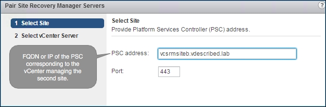
On the Pair Site Recovery Manager Servers wizard's Select Site page, supply the FQDN or IP address of the PSC that corresponds to the secondary site and click on Next:
On the Select vCenter Server screen, select the intended vCenter and supply its SSO credentials. Click on Next to continue:

You will now see a certificate security alert for both the sites. Click on Yes in both dialog boxes to continue.
Once done, you will see both the sites listed:

-
Now, select the site that you just added and click on the
 icon to bring up the Login Site window, prompting the credentials for the vCenter managing the second site:

On the Login Site window, supply the vCenter credentials and click on Login. This completes the site pairing process.
Note
The paring is done only from one of the sites. This is because the pairing process establishes reciprocity by configuring the connection in the reverse direction as well. But when you open the site recovery solution at the remote vCenter Server, you may be prompted to enter the administrator credentials of the other site.
Once you have SRM instances installed and paired, the next step is to install the SRAs. SRAs are coded and provided by the storage vendors. VMware certifies the SRAs and posts them as the compatible ones for the SRM.
The certified versions of the SRA can be downloaded directly from VMware's website. Keep in mind that most vendors publish the updated versions of the SRA at their website before it is certified by VMware. Since SRA is a vendor-supported component, you could choose to install the latest version available from the vendor, if that is known to fix a problem that you are dealing with.
Here is how you can download the SRA:
Go to VMware's website www.vmware.com.
Under the Product Downloads category, navigate to Downloads | vCenter Site Recovery Manager.
Once you are on the download page for vCenter SRM, click on the Go to Downloads hyperlink listed against Storage Replication Adapters.
At the Download Storage Replication Adapters for VMware vCenter Site Recovery Manager page, you will see a list of all the certified SRAs. Click on the Download Now button corresponding to the required SRA.
Once you have installed the SRA at both sites, you will now need to add an array manager at both sites. An array manager is required to discover the replicated LUNs and perform other storage operations initiated by SRM.
Here is how you can add an array manager:
Connect to either of the protected/recovery sites through vCenter Server using vSphere Web Client, navigate to Home | Site Recovery, click on Array Based Replication, and select its Objects tab:

-
Under the Objects tab, click on the
 icon to bring up the Add Array Manager wizard:

The Add Array Manager wizard presents two options:
Add a pair of array managers: This is used when you want to go through the process of adding both the protected and recovery site array managers and enabling the array pair. Use this method during this initial configuration.
Add a single array manager: This is used when you want to add the array managers as separate steps. This can be handy when you want to remove and re-add the array manager corresponding to a particular site.

Select the Add a pair of array managers option, and click on Next to continue.
Select the site pair to configure the array managers, and click on Next to continue:

The Select SRA type screen will list the discovered SRA installed on the SRM servers at both the sites. You will not be able to proceed further if it cannot find the SRA at the paired site:

This will be followed by two configure array manager screens, one each for the protected and recovery sites.
On the first Configure array manager screen, enter a Display Name and the login information required by the protected site's SRA to connect to its storage array. Click on Next to continue:

On the second Configure paired array manager screen, enter a Display Name and the login information required by the recovery site's SRA to connect to its storage array. Click on Next to continue:

On the Enable array pairs screen, you will be presented with a list of discovered array pairs. Select the array pair corresponding to the protected and recovery sites and click on Next to continue:

On the Ready to complete screen, review the summary of the selected settings and click on Finish to create the array manager pair:

The information prompted on the Configure array manager screen (at step 8 and step 9) differs from array to array and from vendor to vendor. It is purely dependent on the SRA being used.
Note
I have used an HP StoreVirtual (left-hand) SRA and have entered the Virtual IP (VIP) of the cluster the Node Storage Module (NSM) is part of. If none of the NSMs in the cluster are involved in the replication for SRM, then I could supply the IP addresses of the involved NSMs separated by a comma.
If the array managers are successfully added, then they will be listed with a Status OK under the Object tab:

Now, you can select either of the array managers and navigate to Manage | Array Pair to view a list of replicated devices and its direction of replication, which will be Outgoing Replication for the Protected Site Array Manager and Incoming Replication for the Recovery Site Array Manager:

Also, to discover and list new replication-enabled LUN devices that are presented to hosts, click on the
 icon to run a Discover Devices operation for the selected array pair.
The Array Pairs tab shows the replication relationship between two arrays. Before you enable the array pair, you need SRA installed and the array manager added at both the sites. For the array manager to detect an array pair, there should be a replication schedule already created between the arrays. Refer to the vendor documentation to understand what a replication schedule would mean for the vendor's array and the procedure to create it. When an array pair is enabled, it tries to discover the LUN devices for which a replication schedule is enabled at the array. However, not all devices with a replication schedule are displayed as a device for the array pair. Only the devices that are presented to a host at the protected site are displayed.
If the replicated LUN devices are not presented to the hosts at the replication source (protected site), then it will complain about this:

For every virtual machine that becomes part of a protection group, SRM creates a shadow virtual machine. A placeholder datastore is used to store files for the shadow virtual machines. The datastore used for this purpose should be accessible to all the hosts in the data center/cluster serving the role of a recovery host. We will learn more about protection groups and shadow virtual machines in the next chapter. For now, understand that configuring placeholder datastores is an essential step in configuring an SRM environment.
Assuming that each of these paired sites are geographically separated, each site will have its own placeholder datastore. The following figure shows the relationship between the site and placeholder datastore:

Here is how you can configure placeholder datastores:
Navigate to Home | Site Recovery:

Click on Sites in the left pane to view the Sites page:

-
Select a site, navigate to Manage | Placeholder Datastores, and click on the
 icon to bring up the Configure Placeholder Datastore window:

On the Configure Placeholder Datastore window, select a datastore to be designated as a placeholder datastore and click on OK:

If successfully designated, it should be listed under the Placeholder Datastores tab:

You should repeat the procedure at the secondary (recovery) site if you plan to failback.
Creating resource, folder, and network mappings facilitates further orchestration of the recovery plan that will be executed for either a planned migration or a failover. Without these mappings, you wouldn't be able to configure protection on the virtual machines and the protection status will indicate that these mappings are missing. We will learn more about protection groups in the next chapter.
Apart from being a requirement for creating protection groups, there are other use cases as well. Here are a few common ones:
|
Use cases |
Mapping to use |
|---|---|
|
If the designated recovery site runs other workloads, then you might want to create a separate folder for the VMs from the protected site |
Folder mappings |
|
If there is a separate cluster/resource pool at the recovery site to host the VMs recovered from the protected site |
Resource mappings |
|
If there are vSwitch/DSwitch port groups at the recovery site for the recovered VMs |
Network mappings |
We need to provide a correlation between the compute resource containers on both the sites. The compute resource containers are cluster, resource pool, and ESXi host. This is achieved with the help of resource mappings.
Resource mappings respects the presence of these containers. This means that, if there is a cluster or a resource pool at the site, then the ESXi hosts are not made available as a selectable compute container.
Here is how you configure resource mapping:
Navigate to Home | Site Recovery and click on Sites to list the paired sites.
-
Select the protected site, navigate to its Manage | Resource Mappings tab, and click on the
 icon to bring up the Create Resource Mapping wizard:

The Create Resource Mapping screen displays the vCenter inventory of the Protected Site on the left pane and the recovery site on the right pane:
Expand the Protected Site's vCenter inventory tree to select the resource container (cluster/resource pool/ESXi host) that you want to map.
Expand the recovery site's vCenter inventory tree to select the destination resource container. Once you have made the selections, click on Add Mappings.

The mapping can be one-to-one or many-to-one. Click on Next to continue.
The Prepare reverse mappings screen will let you configure reverse-directional mappings from the secondary/recovery site to the primary/protected site. This is required if you plan to configure failback. However, reverse mapping is only made available for one-to-one mappings. Choosing Select all applicable will only select the one-to-one mappings. With the selections made, click on Finish to create the resource mapping:

Once configured, the mappings are listed under the Resource Mappings tab:

Folders are inventory containers that can only be created using vCenter Server. They are used to group inventory objects of the same type/purpose for easier management.
There are different types of folders. This is determined by the inventory hierarchy level they are created at. The folder names are as follows:
Data center folder
Hosts and clusters folder
Virtual machine and template folder
Networks folder
Storage folder
The vSphere Web Client provides UI menu options to create a folder of the following types, without needing to navigate to an appropriate inventory hierarchy level to create them:
Hosts and clusters folder
Networks folder
Storage folder
Virtual machine and templates folder
In the case of SRM folder mappings, we will be dealing only with virtual machine folders and their parent data center. You will not be able to configure mapping for any of the other folder types.
Here is how you configure Folder Mappings:
Navigate to Site Recovery Manager Home and click on Sites to list the paired sites.
-
Select the protected site, navigate to its Manage | Folder Mappings tab, and click on the
 icon to bring up the Create Folder Mapping wizard:

The Select creation mode screen presents you with two folder mapping methods—automatic and manual:
The Automatically prepare mappings for networks with matching names option is used to auto create one-to-one mapping between identically named Folders at the Protected and Recovery sites. This is generally the preferred option when you have a lot of folders to map and if they were identically named.
The Prepare mappings manually option is used to create both many-to-one and one-to-one mappings. This option should be used when you do not have identically named virtual machine folders at the secondary site.
Choose the intended option and click on Next to continue:

With both the options, once you have made the necessary selections on the Prepare mappings screen, click on the Add mappings button to confirm the selection. Click on Next to continue:

The Prepare reverse mappings screen will let you configure mapping reverse-directional folder mappings from the Secondary/Recovery site to the Primary/Protected site. This is required if you plan to configure failback. However, reverse mapping is only made available for one-to-one mappings. Choosing Select all applicable will only select the one-to-one mappings. With the selections made, click on Finish to create the folder mapping:

Once done, the mappings created will be listed under the Folder Mappings tab:

Network configuration at the protected and recovery sites need not be identical. Network mappings provide a method to form a correlation between the port groups (standard or distributed) of the protected and recovery sites.
Let's say we have a port group with the name VM Network at the protected site and it is mapped to a port group with the name Recovery Network at the recovery site. In this case, a virtual machine that is connected to VM Network, when failed over, will be reconfigured to use the Recovery Network.
Here is how you configure Network Mappings:
Navigate to Site Recovery Manager Home and click on Sites to list the paired sites.
-
Select the Protected Site, navigate to its Manage | Network Mappings tab, and click on the
 icon to bring up the Create Network Mapping wizard:

As with the folder mapping options, the Select creation mode screen presents you with two network mapping methods as well—automatic and manual mapping. Choose the intended option and click on Next to continue:
The Automatically prepare mappings for networks with matching names option is used to auto create one-to-one mapping between identically named virtual machine port groups at the protected and recovery sites. This is generally the preferred option when you have a lot of port groups to map and if there were identically named.
The Prepare mappings manually option is used to create both many-to-one and one-to-one mappings. This option should be used when you do not have identically named virtual machine port groups at the secondary site.

With both these options, once you have made the necessary selections on the Prepare mappings screen, click on the Add mappings button to confirm the selection. Click on Next to continue:

On the Select test networks screen, you can set a test network for all the recovery site port groups that were selected in the previous mapping screen. By default, the test network is an isolated network (a VM port group with no uplinks). These are used only while testing a recovery LAN. We will learn about recovery plans and their testing in a later chapter. You don't necessarily have to make any changes on this screen. Click on Next to continue:

The Prepare reverse mappings screen will let you configure mapping reverse-directional port group mappings from the Secondary/Recovery site to the Primary/Protected site. This is required if you plan to configure failback. However, reverse mapping is only made available for one-to-one mappings. Choosing Select all applicable will only select the one-to-one mappings. With the selections made, click on Finish to create the network mapping:

Once done, all the mappings created will be listed under the Network Mappings tab:

With SRM implementations, there is a common argument about the placement of the virtual machine swap files. Some would suggest maintaining a separate datastore for the virtual machine swap files, whereas some are against it. Before we try to understand the rationale behind these design choices, it is important to know what a virtual machine swap file is.
Every virtual machine will have a swap file (.vswp). This swap file is created every time a virtual machine is powered on. The size of the swap file is equal to the size of the memory assigned to the virtual machine, unless there is a reservation. If there is a memory reservation, then the size of the swap file will be equal to the size of the unreserved memory. Although rare, some environments use limits on memory as well.
So, the ideal formula to calculate the size of the swap file is as follows:

The default memory reservation is 0 MB and the default limit is equal to the configured size of the memory. By default, the swap file is stored along with the virtual machine in its working directory.
Rationale: The swap file is created every time a virtual machine is powered-on. Since the VM will be powered on at the recovery site, and the swap file will be created at that time, there is no need to replicate the swap files.
The following table illustrates the pros and cons of this:
|
Pros |
Cons |
|---|---|
|
Swap file replication, if avoided, can reduce the bandwidth utilization for storage replication. |
Single point of failure. |
|
Reduces the need for the storage space at the recovery site, which otherwise would be needed for the swap files. |
The swap location should be chosen at a per host level. This would require a lot of manual work in a large environment. |
|
Need to accommodate a separate large LUN. This could affect the available spare capacity of the array. |
Rationale: Apart from the reduced replication bandwidth usage, there is no real advantage of maintaining a separate datastore for the swap files, and most SRM implementations would have already made sure that there would be more than enough bandwidth to make storage replication feasible. Also, not all virtual machines frequently use swap the files unless the vSphere environment is oversubscribed and the virtual machines are frequently contending for memory resources. In most cases, the swap files will be replicated during the initial sync. Subsequent synchronizations will include swap files created consequent to power-off and power-on operations. Keep in mind that a Guest OS reboot will not trigger the recreation of the swap files.
|
Pros |
Cons |
|---|---|
|
No administrative overhead, which would otherwise be needed to configure a swap datastore per host |
Bandwidth wastage, due to the replication of the swap files |
|
No single point of failure |
Wasted storage capacity at the recovery site, which could be otherwise avoided if the swap files are not duplicated on the replica LUNs |
In this chapter, we learned what VMware vCenter Site Recovery Manager is and how it can be installed and configured to lay the groundwork for any SRM environment. In the next chapter, we will learn how to enable protection of the virtual machine workload by creating protection groups and recovery plans.