


Arduino is all about plugging things. We are going to do that in a couple of minutes after we have learned a bit more about microcontrollers in general and especially the big and amazing Arduino family. This chapter is going to teach you how to be totally ready to code, wire, and test things with your new hardware friend. Yes, this will happen soon, very soon; now let's dive in!
A microcontroller is an integrated circuit (IC) containing all main parts of a typical computer, which are as follows:
Processor
Memories
Peripherals
Inputs and outputs
The processor is the brain, the part where all decisions are taken and which can calculate.
Memories are often both spaces where both the core inner-self program and the user elements are running (generally called Read Only Memory (ROM) and Random Access Memory (RAM)).
I define peripherals by the self-peripherals contained in a global board; these are very different types of integrated circuits with a main purpose: to support the processor and to extend its capabilities.
Inputs and outputs are the ways of communication between the world (around the microcontroller) and the microcontroller itself.
The very first single-chip processor was built and proposed by Intel Corporation in 1971 under the name Intel 4004 . It was a 4-bit central processing unit (CPU).
Since the 70s, things have evolved a lot and we have a lot of processors around us. Look around, you'll see your phone, your computer, and your screen. Processors or microprocessors drive almost everything.
Compared to microprocessors, microcontrollers provide a way to reduce power consumption, size, and cost. Indeed, microprocessors, even if they are faster than processors embedded in microcontrollers, require a lot of peripherals to be able to work. The high-level of integration provided by a microcontroller makes it the friend of embedded systems that are car engine controller, remote controller of your TV, desktop equipment including your nice printer, home appliances, games of children, mobile phones, and I could continue…
There are many families of microcontrollers that I cannot write about in this book, not to quote PICs (http://en.wikipedia.org/wiki/PIC_microcontroller) and Parallax SX microcontroller lines. I also want to quote a particular music hardware development open source project: MIDIbox (PIC-, then STM32-based, check http://www.ucapps.de). This is a very strong and robust framework, very tweakable. The Protodeck controller (http://julienbayle.net/protodeck) is based on MIDIbox.
Now that you have understood you have a whole computer in your hands, let's specifically describe Arduino boards!
Arduino is an open source (http://en.wikipedia.org/wiki/Open_source) singleboard-based microcontroller. It is a very popular platform forked from the Wiring platform (http://www.wiring.org.co/) and firstly designed to popularize the use of electronics in interaction design university students' projects.

My Arduino MEGA in my hand
It is based on the Atmel AVR processor (http://www.atmel.com/products/microcontrollers/avr/default.aspx) and provides many inputs and outputs in only one self-sufficient piece of hardware. The official website for the project is http://www.arduino.cc.
The project was started in Italy in 2005 by founders Massimo Banzi and David Cuartielles. Today it is one of the most beautiful examples of the open source concept, brought to the hardware world and being often used only in the software world.
We talk about Arduino family because today we can count around 15 boards 'Arduino-based', which is a funny meta-term to define different type of board designs all made using an Atmel AVR processor. The main differences between those boards are the:
Type of processor
Number of inputs and outputs
Form factor
Some Arduino boards are a bit more powerful, considering calculation speed, some other have more memory, some have a lot of inputs/outputs (check the huge Arduino Mega), some are intended to be integrated in more complex projects and have a very small form factor with very few inputs and outputs… as I used to tell my students each one can find his friend in the Arduino family. There are also boards that include peripherals like Ethernet Connectors or even Bluetooth modules, including antennas.
The magic behind this family is the fact we can use the same Integrated Development Environment (IDE) on our computers with any of those boards (http://en.wikipedia.org/wiki/Integrated_development_environment). Some bits need to be correctly setup but this is the very same software and language we'll use:

Some notable Arduino family members: Uno R3, LilyPad, Arduino Ethernet, Arduino Mega, Arduino Nano, Arduino Pro, and a prototyping shield
A very nice but non-exhaustive reference page about this can be found at http://arduino.cc/en/Main/Hardware.
I especially want you to check the following models:
Throughout this book I'll use an Arduino Mega and Arduino Uno too; but don't be afraid, when you've mastered Arduino programming, you'll be able to use any of them!
We can program and build software quite easily today using a lot of open source frameworks for which you can find a lot of helpful communities on the Web. I'm thinking about Processing (Java-based, check http://processing.org), and openFrameworks (C++-based, check http://www.openframeworks.cc), but there are many others that sometimes use very different paradigms like graphical programming languages such as Pure Data (http://puredata.info), Max 6 (http://cycling74.com/products/max/), or vvvv (http://vvvv.org) for Windows.
Because we, the makers, are totally involved in do-it-yourself practices, we all want and need to build and design our own tools and it often means hardware and electronics tools. We want to extend our computers with sensors, blinking lights, and even create standalone gears.
Even for testing very basic things like blinking a light emitting diode (LED), it involves many elements from supplying power to chipset low-level programming, from resistors value calculations to voltage-driven quartz clock setup. All those steps just gives headache to students and even motivated ones can be put off making just a first test.
Arduino appeared and changed everything in the landscape by proposing an inexpensive and all-included solution (we have to pay $30 for the Arduino Uno R3), a cross-platform toolchain running on Windows, OS X, and Linux, a very easy high-level C language and library that can also tweak the low-level bits, and a totally extensible open source framework.
Indeed, with an all-included small and cute board, an USB cable, and your computer, you can learn electronics, program embedded hardware using C language, and blink your LED.
Hardware prototyping became (almost) as easy as software prototyping because of the high level of integration between the software and the hardware provided by the whole framework.
One of the most important things to understand here is the prototyping cycle.

One easy hardware prototyping steps list
From our idea to our final render, we usually have to follow these steps.
If we want to make that LED blink, we have to define several blinking characteristics for instance. It will help to precisely define the project, which is a key to success.
Then we'll have to sketch a schematic with our Arduino board and our LED; it will dig the question, "How are they connected together?"
The firmware programming using C language can directly be started after we have sketched the circuit because, as we'll see later, it is directly related to the hardware. This is one of the strong powers of Arduino development. You remember? The board design has been designed only to make us think about our project and not to confuse us with very low-level abstract learning bits.
The upload step is a very important one. It can provide us a lot of information especially in case of further troubleshooting. We'll learn that this step doesn't require more than a couple of clicks once the board is correctly wired to our computer.
Then, the subcycle test and fix will occur. We'll learn by making, by testing, and it means by failing too. It is an important part of the process and it will teach you a lot. I have to confess something important here: at the time when I first began my bonome project (http://julienbayle.net/bonome), an RGB monome clone device, I spent two hours fixing a reverse wired LED matrix. Now, I know them very well because I failed one day.
The last step is the coolest one. I mentioned it because we have to keep in our mind the final target, the one that will make us happy in the end; it is a secret to succeed!
In order to understand how to make our nice Arduino board work exactly as we want it to, we have to understand the global software architecture and the toolchain that we'll be using quite soon.
Take your Arduino board in hand. You'll see a rectangle-shaped IC with the word ATMEL written on the top; this is the processor.
This processor is the place that will contain the entire program that we'll write and that will make things happen.
When we buy (check Appendix G, List of Components' Distributors, and this link: http://arduino.cc/en/Main/Buy) an Arduino, the processor, also named chipset, is preburnt. It has been programmed by careful people in order to make our life easier. The program already contained in the chipset is called the bootloader (http://en.wikipedia.org/wiki/Booting). Basically, it takes care of the very first moment of awakening of the processor life when you supply it some power. But its major role is the load of our firmware (http://en.wikipedia.org/wiki/Firmware), I mean, our precious compiled program.
Let's have a look at a small diagram for better understanding:

I like to define it by saying that the bootloader is the hardware's software and the firmware is the user's software. Indeed, it also has some significance because memory spaces in the chipset are not equal for write operations (within a specific hardware which we'll discuss in the future sections of this book). Using a programmer, we cannot overwrite the bootloader (which is safer at this point of our reading) but only the firmware. This will be more than enough even for advanced purposed, as you'll see all along the book.
Not all Arduino boards' bootloaders are equivalent. Indeed, they have been made to be very specific to the hardware part, which provides us more abstraction of the hardware; we can focus on higher levels of design because the bootloader provides us services such as firmware upload via USB and serial monitoring.
Let's now download some required software:
FTDI USB drivers: http://www.ftdichip.com/Drivers/VCP.htm
Arduino IDE: http://arduino.cc/en/Main/Software
Processing: http://processing.org/download/
Processing is used in this book but isn't necessary to program and use Arduino boards.
Tip
What is the Arduino's toolchain?
Usually, we call Arduino's toolchain a set of software tools required to handle all steps from the C code we are typing in the Arduino IDE on our computer to the firmware uploaded on the board. Indeed, the C code you type has to be prepared before the compilation step with avr-gcc and avr-g++ compilers. Once the resulting object's files are linked by some other programs of the toolchain, into usually only one file, you are done. This can later be uploaded to the board. There are other ways to use Arduino boards and we'll introduce that in the last chapter of this book.
Let's find the compressed file downloaded from http://arduino.cc/en/Main/Software in the previous part and let's decompress it on our computer.
Whatever the platform, the IDE works equally and even if I'll describe some specific bits of three different platforms, I'll only describe the use of the IDE and show screenshots from OS X.
There isn't a typical installation of the IDE because it runs into the Java Virtual Machine . This means you only have to download it, to decompress it somewhere on your system, and then launch it and JAVA will execute the program. It is possible to use only the CLI (command-line interface, the famous g33ks window in which you can type the command directly to the system) to build your binaries instead of the graphical interface, but at this point, I don't recommend this.
Usually, Windows and OS X come with Java installed. If that isn't the case, please install it from the java.com website page at http://www.java.com/en/download/.
On Linux, the process really depends on the distribution you are using, so I suggest to check the page http://www.arduino.cc/playground/Learning/Linux and if you want to check and install all the environment and dependencies from sources, you can also check the page http://www.arduino.cc/playground/Linux/All.
In Windows, let's click on the .exe file included in the uncompressed folder. On OS X, let's click on the global self-contained package with the pretty Arduino logo. On Linux, you'll have to start the Arduino script from the GUI or by typing in the CLI.
You have to know that using the IDE you can do everything we will make in this book.
The IDE provides a graphical interface in which you can write your code, debug it, compile it, and upload it, basically.
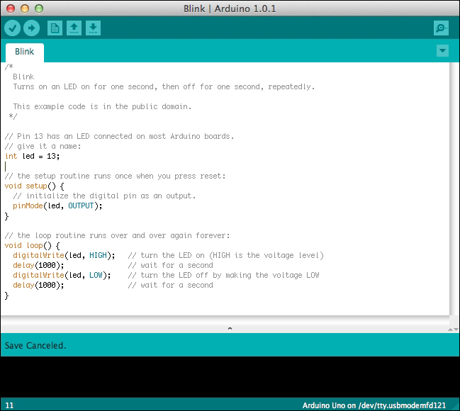
The famous Blink code example opened in the Arduino IDE
There are six icons from left to right that we have to know very well because we'll use them every time:
Verify (check symbol): This provides code checking for errors
Upload (right-side arrow): This compiles and uploads our code to the Arduino board
New (small blank page): This creates a new blank sketch
Open (up arrow): This opens a list of all sketches already existing in our sketchbook
Save (down arrow): This saves our sketch in our sketchbook
Serial Monitor (small magnifying glass): This provides the serial monitoring
Each menu item in the top bar provides more options we will discover progressively all throughout this book.
However, the Tools menu deserves closer attention:
Auto Format: This provides code formatting with correct and standard indentations
Archive Sketch: This compresses the whole current sketch with all files
Board: This provides a list of all boards supported
Serial Port: This provides a list of all serial devices on the system
Programmer: This provides a list of all programmer devices supported and used in case of total reprogramming of the AVR chipset
Burn Bootloader: This is the option used when you want to overwrite (or even write) a new bootloader on your board.

The Tools menu
The preferences dialog is also a part we have to learn about right now. As usual, the preferences dialog is a place where we don't really need to go often but only for changing global parameters of the IDE. You can choose the sketchbook location and the Editor language in this dialog. You can also change a couple of bits like automatic check-up of IDE updates at start up or Editor font size.
The sketchbook concept will make our life easier. Indeed, the sketchbook is a folder where, basically, all your sketches will go. On my personal point of view, it is very precious to use it like this because it really organizes things for you and you can retrieve your pieces of code easier. Follow me there; you'll thank me later.
When we start a sketch from scratch, we basically type the code, verify it, upload it, and save it. By saving it, the first time, the IDE creates a folder in which it will put all the files related to our current sketch. By clicking on the sketch file inside this folder, the Arduino IDE will open and the related code will be displayed in the edit/typing part of the window.
We are almost done!
Let's install the drivers of the Arduino USB interface on our system.
Arduino boards provide an USB interface. Before we plug the USB cable and link the board to our computer, we have to install specific drivers in the latter.
There is a huge difference between Windows and OS X here; basically, OS X doesn't require any specific drivers for Arduino Uno or even Mega 2560. If you are using older boards, you'd have to download the latest version of drivers on the FTDI website, double-click the package, then follow instructions, and finally, restart your computer.
Let's describe how it works on Windows-based systems, I mean, Windows 7, Vista, and XP.
It is important to follow the steps mentioned next to be able to use the Arduino Uno R3 and some other boards. Please check the Arduino website for up-to-date references.
Plug your board in and wait for Windows to begin the driver installation process. After a few moments, the process fails.
Click on the Start menu, and open Control Panel.
In Control Panel, navigate to System and Security. Next, click on System. Once the System window is up, open Device Manager.
Look under Ports (COM & LPT). Check the open port named Arduino UNO (COMxx).
Right-click on the Arduino UNO (COMxx) port and choose the Update Driver Software option.
Next, choose the Browse my computer for driver software option.
Finally, navigate and select the Uno's driver file, named
ArduinoUNO.inf, located in theDriversfolder of the Arduino software download (be careful: not theFTDI USB Driverssubdirectory).Windows will finish the driver installation from there and everything will be fine.
When you connect the board, Windows should initiate the driver installation process (if you haven't used the computer with an Arduino board before).
On Windows Vista, the driver should be automatically downloaded and installed. (Really, it works!)
On Windows XP, the Add New Hardware wizard will open:
When asked Can Windows connect to Windows Update to search for software? select No, not this time. Click on Next.
Select Install from a list or specified location (Advanced) and click on Next.
Make sure that Search for the best driver in these locations is checked, uncheck Search removable media, check Include this location in the search, and browse to the drivers/FTDI USB Drivers directory of the Arduino distribution. (The latest version of the drivers can be found on the FTDI website.) Click on Next.
The wizard will search for the driver and then tell you that a USB Serial Converter was found. Click on Finish.
The new hardware wizard will appear again. Go through the same steps and select the same options and location to search. This time, a USB Serial Port will be found.
You can check that the drivers have been installed by opening Windows Device Manager (in the Hardware tab of the System control panel). Look for a USB Serial Port in the Ports section; that's the Arduino board.
Now, our computer can recognize our Arduino board. Let's move to the physical world a bit to join together the tangible and intangible worlds.
Arduino is all about electronic, and electronic refers to electricity. This may be your first dive into this amazing universe, made of wires and voltages, including blinking LEDs and signals. I'm defining several very useful notions in this part; you can consider turning down the corner of this page and to come back as often as you need.
Here, I'm using the usual analogy of water. Basically, wires are pipes and water is electricity itself.
Voltage is a potential difference. Basically, this difference is created and maintained by a generator. This value is expressed in Volt units (the symbol is V).
The direct analogy with hydraulic systems compare the voltage to the difference of pressure of water in two points of a pipe. The higher the pressure, the faster the water moves, for a constant diameter of pipe of course.
We'll deal with low voltage all throughout this book, which means nothing more than 5 V. Very quickly, we'll use 12 V to supply motors and I'll precise that each time we do.
When you switch on the generator of closed circuits, it produces and keeps this potential difference. Voltage is a difference and has to be measured between two points on a circuit. We use voltmeters to measure the voltage.
Current can be compared to the hydraulic volume flow rate, which is the volumetric quantity of flowing water over a time interval.
The current value is expressed in Ampères (the symbol is A). The higher the current, the higher will be the quantity of electricity moving.
A flow rate doesn't require two points to be measured as a difference of pressure; we only need one point of the circuit to make our measurement with an equipment named Ampere meter.
In all of our applications, we'll deal with direct current (DC), which is different from alternative current (AC).
Power is a specific notion, which is expressed in Watt (the symbol is W).
Following is a mathematical relationship between voltage, current, and power:
P = V x I
where, P is the power in Watt, V the voltage in V, and I the current in Ampères.
Are you already feeling better? This analogy has to be understood as a proper analogy, but it really helps to understand what we'll make a bit later.
Following the same analogy, resistors are small components that slow down the flow of current. They are more resistive than any piece of wire you can use; they generally dissipate it as heat. They are two passive terminal components and aren't polarized, which means you can wire them in both directions.
Resistors are defined by their electrical resistance expressed in Ohms (the symbol is Ω).
There is a direct mathematical relation between voltage measured at the resistor sides, current, and resistance known as the Ohm's law:
R = V / I
where R the electrical resistance in Ohms, V the voltage in Volts, and I the current in Ampères.
For a constant value of voltage, if the resistance is high, the current is low and vice-versa. It is important to have that in mind.
On each resistor, there is a color code showing the resistance value.
There are many types of resistors. Some have a constant resistance, some others can provide different resistance values depending on physical parameters such as temperature, or light intensity for instance.
A potentiometer is a variable resistor. You move a slider or rotate a knob and the resistance changes. I guess you begin to understand my point…
A capacitor (or condenser) is another type of component used very often. The direct analogy is the rubber membrane put in the pipe: no water can pass through it, but water can move by stretching it.
They are also passive two-terminal components but can be polarized. Usually, small capacitors aren't.
We usually are saying that capacitors store potential energy by charging. Indeed, the rubber membrane itself stores energy while you stretch it; try to release the stretched membrane, it will find its first position.
Capacitance is the value defining each capacitor. It is expressed in Farads (the symbol is F).
We'll stop here about capacitance calculations because it involves advanced mathematics which isn't the purpose of this book. By the way, keep in mind the higher the capacitance, more will be the potential the capacitor can store.
A diode is again a two-terminal passive component but is polarized. It lets the current pass through it only in one direction and stop it in the other. We'll see that even in the case of direct current, it can help and make our circuits safer in some cases.
LEDs are a specific type of diode. While the current passes through them in the correct direction, they glow. This is a nice property we'll use to check if our circuit is correctly closed in a few minutes.
Transistor is the last item I'm describing here because it is a bit more complex, but we cannot talk about electronics without quoting it.
Transistors are semiconductor devices that can amplify and switch electronics signals and power, depending on how they are used. They are three-terminal components. This is the key active component of almost all modern electronics around us. Microprocessors are made of transistors and they can even contain more than 1 billion of them.
Transistors in the Arduino world are often used to drive high current, which couldn't pass through the Arduino board itself without burning it. In that case, we basically use them as analogue switches. When we need them to close a circuit of high currents to drive a motor for instance, we just drive one of their three terminals with a 5 V coming from the Arduino and the high current flows through it as if it had closed a circuit. In that case, it extends the possibilities of the Arduino board, making us able to drive higher currents with our little piece of hardware.
With the previous analogy, we can understand well that a circuit needs to be closed in order to let the current flow.
Circuits are made with wires, which are basically conductors. A conductor is a matter with a resistance near to zero; it lets the current flow easily. Metals are usually good conductors. We often use copper wires.
In order to keep our wiring operations easy, we often use pins and headers. This is a nice way to connect things without using a soldering iron each time!
By the way, there are many ways to wire different components together. For our prototyping purpose, we won't design printed circuit board or even use our soldering iron; we'll use breadboards!
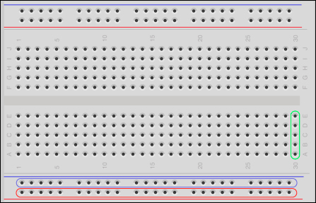
A breadboard with its buses blue and red and its numerous perforations
Breadboards are the way to rapid prototyping and this is the way to go here.
Basically, breadboards consists of a piece of plastic with many perforations in which there are small pieces of conductors allowing to connect wires and components' leads inside.
The distance between two perforations is 2.54 mm (equal to 0.1") that is a standard; for instance, dual in-line package integrated circuits' leads are all separated by this particular distance and thus, you can even put IC on breadboards.
As we saw on the previous screenshot, there are buses and terminals strips.
Buses are series of five perforations in the central part and put in column for which the underlying conductors are connected. I have surrounded one bus with a green stroke.
Terminals are special buses usually used for power supplying the circuit and appear in between blue and red lines. Usually, we use blue for ground lines and red for voltage source (5 V or 3.3 V in some cases). A whole line of terminals has its perforations all connected, providing voltage source and ground easily available on all the breadboard without having to use a lot of connection to the Arduino. I surrounded 2 of the 4 terminals with red and blue strokes.
Breadboards provide one of the easiest ways of prototyping without soldering. It also means you can use and reuse your breadboards throughout the years!
I discovered the open source Fritzing project (http://fritzing.org) when I needed a tool to make my first master classes slideshows schematic around the Protodeck controller (http://julienbayle.net/protodeck) I built in 2010.
Fritzing is defined as an open source initiative to support designers, artists, researchers and hobbyists to work creatively with interactive electronics. It sounds as if it had been made for us, doesn't it?
You can find the Fritzing's latest versions at http://fritzing.org/download/.
Basically, with Fritzing, you can design and sketch electronic circuits. Because there are many representations of electronic circuits, this precious tool provides two of the classic ones and a PCB design tool too.
Considering the first practical work we are going to do, you have to take your breadboard, your Arduino, and wire the lead and the resistor exactly as it is shown in the next screenshot:
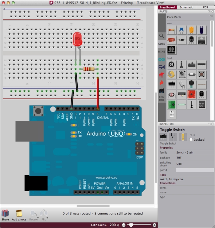
The breadboard view showing our first circuit
The breadboard view is the one that looks the most like what we have in front of us on the table. You represent all wires and you connect a virtual breadboard to your Arduino and directly plug components.
The magic lies in the fact that the schematic is automatically build while you are sketching in the breadboard view. And it works both ways! You can make a schematic, and Fritzing connect components in the breadboard view. Of course, you'd probably have to place the part in a more convenient or aesthetical way, but it works perfectly fine. Especially, the Autorouter helps you with making all wires more linear and simple.
In the next screenshot, you can see the same circuit as before, but shown in the schematic view:
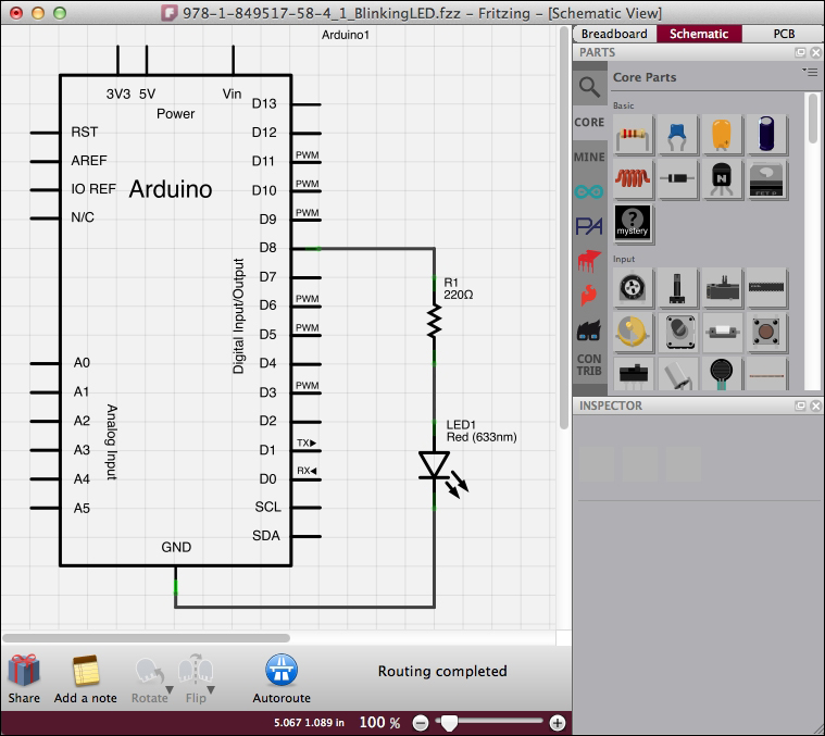
The schematic view representing the circuit diagram
There are a lot of components already designed especially for Fritzing and you can even create yours quite easily. The page to visit for this purpose is http://fritzing.org/parts/.
The native library contains all parts required in all schematics of this book from all Arduino boards, to any discrete components and IC too. Indeed, all schematics of this book have been made using Fritzing!
Now that you know how to wire things without any soldering iron, and how to quietly sketch and check things on your computer before you do it for real on your desktop, let's learn a bit about power supply.
We learned a bit more about electricity before, but how can I supply all my circuits in real life?
Arduino boards can be supplied in three different ways:
The USB cable contains four cables: two for data communication purpose and two for power supply. Those latter are basically used to supply Arduino when you are connecting it to the computer via USB.
USB is a special communication bus that provides 5 V but no more than 500 mA. (0.5 A) It means we have to use another supply source in special projects where we need a lot of LED, motors, and other devices that drive a lot of current.
Tip
What adapter can I use with my Arduino?
Arduino Uno and Mega can be directly supplied by DC Adapter but this one has to respect some characteristics:
The output voltage should be between 9 V and 12 V
It should be able to drive at least 250 mA of current
It must have a 2.1 mm power plug with center positive
Usually, if you ask yourself about the fact whether to use an adapter or not, it means you need more current than the USB's 500 mA (Practically, ask yourself this question whether you need around 400 mA).
Using USB or the 2.1 mm power plug with an adapter are the safest ways to use Arduino boards for many reasons. The main one is the fact that those two sources are (hopefully) clean, which means they deliver a regulated voltage.
However, you have to change something on the board if you want to use one or the other source: a jumper has to be moved to the right position:
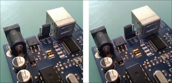
On the left, the jumper is set to USB power supply and on the right, it is set to external power supply
Usually, an idle Arduino board drains around 100 mA and, except in specified cases (see Chapter 9, Making Things Move and Creating Sounds), we'll use the USB way of supply. This is what you have to do now: plug in the USB cable both in the Arduino and your computer.
Launch the Arduino IDE too, and let's move further to the hardware Hello World of our system, I call that the Hello LED!
If your Arduino doesn't contain any firmware, the LED probably does nothing. If you check the built-in LED on the Arduino board itself, that one should blink.
Let's take the control over our external cute LED plugged in the breadboard right now.
If you remember correctly, this is the first question we have to ask. Of course, we bypassed this step a bit especially about the hardware part because I had to explain things while you were wiring, but let's continue the prototyping process explained in part by checking the code and uploading it.
We want to make our LED blink. But what blink speed ? How much time? Let's say we want to make it blink every 250 ms with a one second pause between the blinks. And we want to do that infinitely.
If you check the schematic, you can understand that the LED is put between the ground, and the line to the digital output pin number 8.
There is a resistor and you now know that it can consume a bit of energy by resisting to the current flowing to the LED. We can say the resistor protects our LED.
In order to make the LED light up, we have to create a flow of current. Sending +5 V to the digital output number 8 can do this. That way, there will be a potential difference at the two leads of the LED, driving it to be lighted. But the digital output shouldn't be at +5 V at each time. We have to control the moment when it will provide this voltage. Still okay?
Let's summarize what we have to do:
Put the 5 V to the digital output 8 during 250ms.
Stop to drive the digital output 8 during 1s.
Restart this every time the Arduino is powered
If you followed the previous page correctly, you already have your Arduino board wired to the computer via your USB cable on one side, and wired to the breadboard on the other side.
Now, launch your Arduino IDE.
If you already tested your IDE by loading some examples, or if you already wrote some piece of code, you have to click on the New icon in order to load a blank page, ready to host our Blink250ms code:
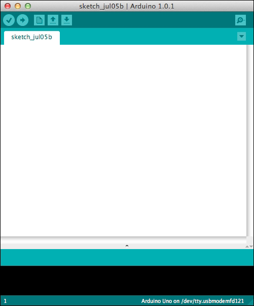
A nice and attractive blank page
The IDE has to know with which board it will have to communicate. We will do it in the following steps:
Go to the Tools menu and choose the correct board. The first one is Arduino Uno:

Choose the board you are using
Once we have done that, we have to choose the correct serial port. Go to the Tools menu again and choose the correct serial port:
On OS X, the correct one begins with /dev/tty.usbmodem for both Uno and Mega 2560 and with /dev/tty.usbserial for older boards.
On Windows, the correct port is usually COM3 (COM1 and COM2 are often reserved by the operating system). By the way, it can also be COM4, COM5, or whatever else. To be sure, please check the device manager.
On Linux, the port is usually /dev/ttyUSB0:

Choose the serial port corresponding to your board
Now, our IDE can talk to our board. Let's push the code now.
The following is the complete code. You can find it in the zip file in the Chapter01/Blink250ms/ folder:
Tip
Downloading the example code
You can download the example code files for all Packt books you have purchased from your account at http://www.packtpub.com. If you purchased this book elsewhere, you can visit http://www.packtpub.com/support and register to have the files e-mailed directly to you.
/*
  Blink250ms Program
  Turns a LED connected to digital pin 8 on for 250ms, then off for 1s, infinitely.
  Written by Julien Bayle, this example code is Creative Commons CC-BY-SA
 */

// Pin 8 is the one connected to our LED
int ledPin = 8;                // ledPin is an integer variable initialized at 8

// --------- the setup routine runs once when you power up the board or push the reset switch
void setup() {
  pinMode(ledPin, OUTPUT);     // initialize the digital pin as an output because we want it to source a current
}

// --------- the loop routine runs forever
void loop() {
  digitalWrite(ledPin, HIGH);   // turn the LED on (HIGH is a constant meaning a 5V voltage)
  delay(250);                   // wait for 250ms in the current state
  digitalWrite(ledPin, LOW);    // turn the LED off (LOW is a constant meaning a 5V voltage)
  delay(1000);                  // wait for 1s in the current state
}
Let's comment it a bit. Indeed, we'll learn how to code our own C code in the next chapter, then I'll only describe this one and give you some small tips.
First, everything between /* and */, and everything after // are just comments. The first form is used for comments more than one line at a time, and the other one is for one line commenting only. You can write any comments like that and they won't be considered by the compiler at all. I strongly advice you to comment your code; this is another key to succeed.
Then, the first part of the code contains one variable declaration and initialization:
int ledPin = 8;
Then, we can see two particular structures between curly braces:
void setup() {
  pinMode(ledPin, OUTPUT);
}
void loop() {
  digitalWrite(ledPin, HIGH);
  delay(250);
  digitalWrite(ledPin, LOW);
  delay(1000);
}
The first one (setup()) is a function that is executed only one time when the Arduino board is started (or reseted); this is the place where we are telling the board that the pin where the LED is connected is an output, that is, this pin will have to drive current while activated.
The second one (loop()) is a function executed infinitely when the Arduino board is supplied. This is the main part of our code in which we can find the steps we wanted to light up the LED for 250 ms and switch off the LED for 1 s, repeatedly.
If you correctly followed and manipulated the hardware and the IDE as explained before, we are now ready to upload the code on the board.
Just click on the Upload button in the IDE. You'll see the TX and RX LEDs blinking a bit and … your LED on your breadboard should blink as expected. This is our very first HELLO LED! example and I hope you liked it.
If you want to tweak the code a bit, you can replace the following line:
delay(1000);
With the following line, for instance:
delay(100);
Now upload this new code again and see what happens.
In this chapter itself, we learnt a bit about Arduino and microcontrollers, and about electricity too. That will help us in the next chapters in which we will talk a lot about circuits.
We also installed the IDE that we will use every time while programming Arduino boards and we even tested the first piece of code. We are now able to continue our travel by learning more about the C language itself.


