


 Download code from GitHub
Editing a Viking Scene with a Basic 3D Workflow
In this chapter, you'll get your first taste of the 3D workflow. Now that we've covered some basic 3D terminology, we can learn the navigation controls, menus, and a few modeling tools. Whether you're new to 3D or you've used other 3D software before, this chapter will help you get an idea of how things are done in Blender 2.8.
Many of the 3D modeling concepts we're about to learn are interdependent on one another. It would be difficult and very slow to learn in order of the smallest features to the largest features. If we take things too slowly, you'll be so bored that you'll fall asleep before getting to do anything exciting, so we're going to keep things moving. If this chapter seems like it's going fast, don't worry; we will break down these concepts in more detail in subsequent chapters.
Once we've finished the boring textbook stuff, we'll dive right in and work on our first project in Blender 2.8! This project is a little Viking themed scene with a training dummy, arrows, and most importantly, a Viking helmet! We'll get some practice transforming objects by sticking the arrows into the dummy's chest, and we'll really have some fun by adding horns and other features to the Viking helmet.
In this chapter, we will cover the following topics:
- Setting up the source files
- Using the Outliner to organize a scene
- Navigating the 3D Viewport
- Using the Toolbar
- Basic transformations in Object Mode
- Editing the Viking helmet
- Rendering the final image
Setting up the source files
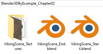
For this project, you'll need the files from Blender3DByExample_Chapter02.zip, which can be downloaded here: https://github.com/PacktPublishing/Blender-3D-By-Example-Second-Edition. Download and unzip the folder. You should now have a directory called Blender3DByExample_Chapter02 that contains the starting project file and a folder that contains all of the texture files that are required:
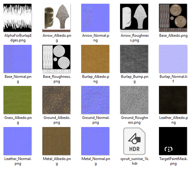
Blender saves projects in a proprietary format called .blend – these files store everything you need for a 3D scene: models, animations, lights, you name it! .blend files can also include image textures, though most 3D artists choose to keep the texture files separate so that the .blend file will take up less room on the computer. For this chapter, the textures can be found inside the VikingScene_Textures folder, as you can see here:
Now that we have our files, we can get started. Open the VikingScene_Start.blend file to begin this project. You can open a .blend file by dragging and dropping it into Blender, or by going to the File menu and choosing Open.... We will start by learning how to use the Outliner panel.
Using the Outliner to organize a scene
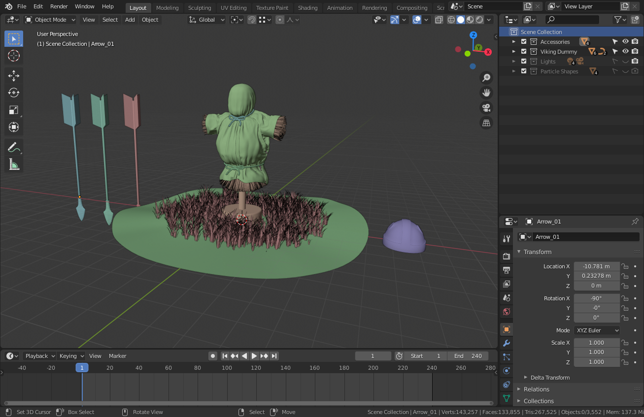
Welcome to your first Blender scene! We had a brief introduction to the user interface in Chapter 1, Introduction to 3D and the Blender User Interface, but now we can see it with our own eyes. The largest area of the UI is dedicated to the 3D Viewport (or just "Viewport" for short). You can see all of the 3D objects inside this area. This scene has been set to use the new Random Colors feature, which gives all of the objects false colors so that they are easier to identify in the Viewport, as shown in the following screenshot:
The random colors are helpful, but there is an even better way to discover the contents of a scene: the Outliner. The Outliner can be found in the top-right corner of the UI. Let's learn how to use it to our advantage.
We can look at the Outliner to get a sense of what's in this project file. The Outliner in Blender 2.8 has been upgraded with a new feature called Collections. Collections are similar to layers or groups in other applications. These collections are a very powerful feature as they can have any type of object grouped within them, including other collections.
Let's take a look at how this scene uses the Outliner to organize the objects. In the following screenshot, you can see that there are five collections in this .blend file; a top-level collection and four collections inside it:
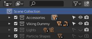
The top-level collection is called Scene Collection. This is a default collection that contains everything else within the scene. The indentation in the Outliner shows that the bottom four collections are all grouped inside the Scene Collection.
Next to each collection are orange icons with little numbers that indicate how many of each type of object is inside them:
- Accessories has four mesh objects.
- Viking Dummy has six mesh objects and two curve objects.
- Lights has four light objects and one camera object.
- Particle Shapes has four mesh objects.
To the left of each collection is a little arrow that indicates that the collections are collapsed in the Outliner. Let's expand two of these collections to see the list of objects that belong to each collection:
- Click on the little arrow to the left of the Accessories collection.
- Click on the little arrow to the left of the Viking Dummy collection.
Good! Now, we can see the expanded hierarchy for each collection, as shown here:
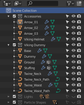
This Viking scene is relatively small with 21 objects in total, but it's still important to stay organized. Imagine working in a project that has hundreds of objects. The Outliner fills up really fast, so placing objects into collections is a terrific way to stay organized.
The bottom two collections are grayed-out because their visibility has been turned off. On the right-hand side of the Outliner, you can see three icons for each row, as shown in the following screenshot:
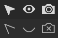
These three icons represent Restriction Toggles. From left to right, we have Selectable, Hide in Viewport, and Disable in Renders:
- When the Selectable toggle is set to its grayed-out state, the object can't be selected by clicking on it in the Viewport.
- When the Hide in Viewport toggle is set to its grayed-out state, the object can't be seen in the Viewport.
- When the Disable in Renders toggle is set to its grayed-out state, the object will not show up in the final image.
The Lights collection has both its Selectable and Hide in Viewport toggles grayed-out so that the lights will not be in the way while we work in this scene. However, the Disable in Renders toggle has not been grayed-out, which means that the lighting will turn on for the final image.
The Particle Shapes collection is for storing objects that make up the particles, such as the grass on the ground and the straw that fills the dummy. Particles are an advanced feature, so don't worry about this for now – just know that this collection is still being used in the scene, even though all three of its toggles are grayed-out.
You may have noticed that the other objects in the Outliner also have little arrows and can be expanded. This is useful for advanced users because you can see all of the data associated with each object, similar to how we can see all of the objects associated with each collection. But let's not get ahead of ourselves – you're probably itching to get into the 3D scene!
Navigating the 3D Viewport
3D navigation is essential when working on any project in Blender, so let's practice what we learned in the Basic 3D Navigation Controls section of Chapter 1, Introduction to 3D and the Blender User Interface, before learning one more very important navigation feature.
As we have already learned, Blender's 3D navigation controls are all about using the middle mouse button (MMB). Let's start by rotating the view:
- Move your mouse into the 3D Viewport.
- Press and hold the middle mouse button.
- Drag your mouse around to rotate the viewing angle.
Notice that the focal point of the view is focused on the Viking dummy in the center. When we rotate, our view always orbits around the current focal point. We'll see why this is important after we practice our other controls.
Once you're comfortable with orbiting the Viking dummy, let's try panning:
- Make sure the mouse is still in the 3D Viewport.
- Hold down the Shift key, then press and hold the middle mouse button.
- Drag your mouse around to pan the view.
Panning shifts the focal point of the Viewport. If we rotate the view now, we will orbit around the new focal point. Both orbiting and zooming are relative to the focal point. Let's give zooming a shot now:
- Once again, make sure the mouse is in the 3D Viewport.
- Hold down the Ctrl key, then press and hold the middle mouse button.
- Drag your mouse up and down to zoom in and out.
As we rotate, pan, and zoom around the scene, the focal point of the Viewport will inevitably get stuck in an awkward position. Eventually, navigating the Viewport will become very difficult and frustrating. This is a common issue in all 3D software.
To fix this issue, we can choose an object that we want to focus on, then frame it by using the View Selected feature (also known as the Frame Selected feature). First, we'll pick an object that we want to work with:
- Select the Dummy object by clicking on it in the 3D Viewport or in the Outliner.
The object will have an orange outline in the Viewport to indicate that it is selected. Now, we need to frame it. There are many ways to do this, but Blender 2.8 has a new pie menu that we can use for easy Viewport navigation.
- Move the mouse over the 3D Viewport so that the keyboard shortcuts behave correctly.
- Press the Tilde key (~ ) to bring up the View pie menu.
The View pie menu is one of many pie menus in Blender 2.8. When activated, pie menus bring up a quick list of menu options in a circular pattern around the mouse, as shown in the following screenshot:
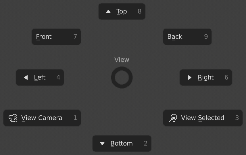
Each option on the pie menu takes up a slice of space around the mouse (like a slice of pie) and can be selected by simply moving your mouse in the direction of the menu option you want and then clicking.
We will become familiar with the other options of this pie menu later in this book, but for now, we just need the View Selected option:
- Make sure the View pie menu is still open.
- Move the mouse diagonally down and to the right to highlight the View Selected option.
- Click while the View Selected option is highlighted.
The nice thing about pie menus is that you don't have to click directly on the menu option; all you have to do is aim the mouse in the general direction of the "slice" of the pie menu that you want and then click.
Excellent – the Viewport's focal point has been reset so that the Dummy object is centered in the view. You should get familiar with using this navigation feature since it will come up over and over again in our workflow.
Play around with the navigation controls until you're comfortable with them – you'll be using them from here on out. Practice rotating, panning, and zooming. Try selecting different objects in the scene and use the View Selected option to frame them within the 3D Viewport. One more time, here are the navigation controls we covered:
- Rotate: MMB and drag
- Zoom: Ctrl + MMB and drag OR scroll wheel.
- Pan: Shift + MMB and drag.
- View Selected: Tilde ~ hotkey | View Selected OR period . on the number pad.
When you feel comfortable with these controls, you can move on to the next section of this chapter, where we'll have a look at Blender's new Toolbar.
Using the Toolbar
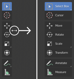
In Blender 2.8, there is a new user-friendly Toolbar attached to the left-hand side of the 3D Viewport. The Toolbar provides an assortment of large icons, with each icon representing a tool. By default, the Toolbar is collapsed into a single column, but we can expand it to show the names of all of the tools. Let's expand the Toolbar now:
- Hover your mouse over the right-hand side edge of the Toolbar until your mouse turns into a double arrow.
- Left-click and drag to the right to expand the Toolbar, as shown in the following screenshot:
Now that the Toolbar has been expanded, let's learn about some of the tools.
The first tool in the Toolbar is the Select Box tool, which is highlighted in blue to indicate that it is active. When a tool is active, it can be used by clicking in the 3D Viewport with the Left Mouse Button (LMB). The Select Box tool lets us draw a box selection by clicking and dragging over multiple objects.
Directly beneath the Select Box tool is the Cursor tool. This will let us place the 3D cursor in the scene. You'll learn more about what the 3D cursor is and how to use it in the next project, so don't worry about it for now.
The next four tools are used for transformations: Move, Rotate, Scale, and Transform. The names of these tools should sound familiar from what we learned in the first chapter. Clicking on a tool in the Toolbar will activate it, and a gizmo will appear in the 3D Viewport. We use gizmos to interact with the tools from the Toolbar. The gizmos for the four transform tools are shown in the following image:
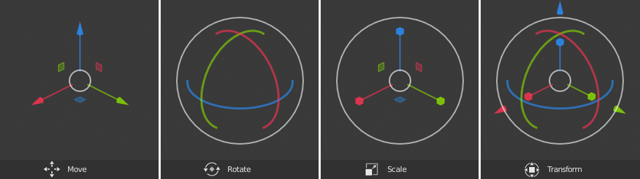
Let's learn more about these four gizmos:
- Move: The Move tool gizmo has three colored arrows, one for each axis (red for X, green for Y, and blue for Z). Clicking and dragging on these arrows will move the selected object.
- Rotate: The Rotate gizmo also has three colored handles, but this time they are shaped like semicircles instead of arrows. The colors still correspond to the same X, Y, and Z axes. Clicking and dragging on these semicircles will rotate the selected object.
- Scale: This gizmo looks almost identical to the Move gizmo but, instead of little arrows, the tips are shaped like little cubes. Clicking and dragging on these little cubes will scale the selected object.
-
Transform: The Transform gizmo is just a combination of the previous three gizmos. Some users like to have all of these gizmos active at once, but it can be a little overwhelming.
The last few tools in the Toolbar are for advanced workflows, so we'll skip them for now. Next, we'll practice with the basic transformation tools by moving, rotating, and scaling the three arrow objects in the scene.
Basic transformations in Object Mode
Before we can edit the Viking helmet in this project, we need to practice using the transformation tools. We already learned how to activate tools, and we know what the gizmos look like, so now it's time to stick some arrows in the dummy!
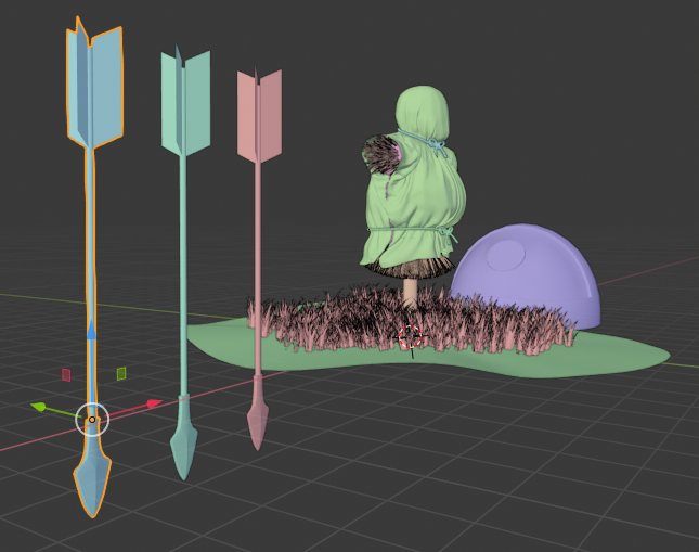
- Click on the Move tool in the Toolbar to activate it.
- Select the Arrow_01 object by clicking on it in the Outliner or in the 3D Viewport.
- Press the tilde ~ key to bring up the View pie menu.
- Choose the View Selected option to frame the arrow.
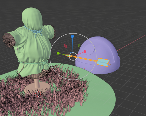
- Rotate the view with the middle mouse button so that we can see the dummy in the middle of the scene, as shown in the following screenshot:
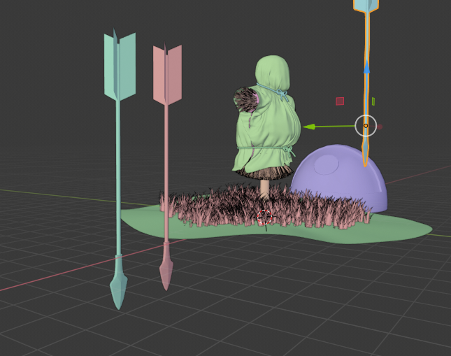
- Left-click on the red axis arrow of the Move gizmo and drag it sideways toward the Dummy object.
- Next, click and drag the green axis arrow of the gizmo to pull it toward the front of the Dummy object.
- Finally, click and drag upward on the blue axis arrow to bring it up to the chest area of the Dummy object.
When you're done moving the arrow along all three axes, the arrow should be positioned similarly to what's shown in the following screenshot:
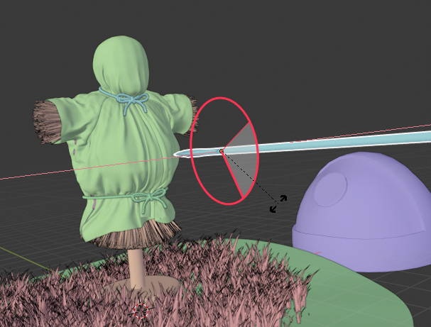
Now that the arrow has been moved into position, it's time to rotate it. First, we'll frame the arrow in the view, and then we'll use the rotate tool:
- Press the tilde ~ key to bring up the View pie menu.
- Choose the View Selected option to frame the arrow.
- Select the Rotate tool from the Toolbar.
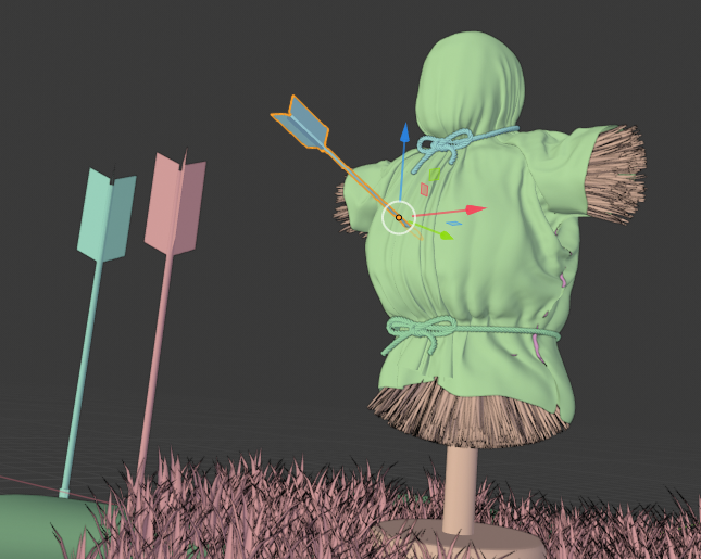
- Click and drag on the red axis of the rotation gizmo to aim the arrow at the dummy's chest, as shown in the following screenshot:
This is looking good, but the arrow is way too big – it's an arrow, not a spear! Let's size it down with the Scale tool. When we scale objects, we usually want to scale along all three axes at once to keep the object's size proportional. Luckily, the scale tool makes this really easy as we can use the white circles of the gizmo. Let's give it a shot:
- Click on the Scale tool in the Toolbar to activate it.
- Hover your mouse over the Scale gizmo so that the gizmo's white circles light up.
- Click and drag inward to make the arrow smaller.
That will do the trick! The arrow should now be a similar size to what you can see in the following screenshot:
Excellent! Now, we need to go back to the Move tool one last time and stick that arrow into the dummy's chest. Just like with the Scale tool, you can click on the Move gizmo's white circle to move the object along all three axes at once. Let's try this now:
- Click on the Move tool in the Toolbar to activate it.
- Rotate the view as needed so that we can move the Arrow_01 object toward the Dummy object.
- Hover your mouse over the Move gizmo's white circle.
- Click and drag the white circle toward the dummy until the tip of the Arrow_01 object pierces the Dummy object, as shown in the following screenshot:
Good work, but there are two more arrows. Use what we just learned to finish placing all three arrows into the dummy's chest:
- Select the Arrow_02 object.
- Press the tilde ~ key to bring up the View pie menu and choose the View Selected option.
- Use the Move tool to move it in front of the dummy.
- Use the Rotate tool to aim the arrow tip at the dummy.
- Use the Scale tool to shrink the arrow down to a more appropriate size.
- Use the Move tool again to stick the arrow in the dummy's chest.
- Repeat these steps again for the Arrow_03 object.
When you're finished placing the arrows, we can move on to editing the Viking helmet!
Editing the Viking helmet
Now that we've had some practice transforming objects, we're ready for the main event: editing the Viking helmet. This is the largest part of this chapter, so we'll break it down into a few small subsections, as follows:
- Preparing to work on the helmet
- Making changes to components in Edit Mode
- Adding the nose guard
- Adding the horns
- Adding the studs
- Returning to Object Mode to finish
We will begin by preparing to work on the helmet so that the rest of the objects in the scene don't get in the way.
Preparing to work on the helmet
Let's take a moment to prepare for working on the helmet. In a typical 3D workflow, we edit one object at a time. We can use a special view mode called Local View to temporarily hide all of the other objects in the scene. Let's do this now:
- Select the Viking Helmet object.
- Look at the header of the 3D Viewport and find the View menu at the top-left.
- Click on the View menu to open it and choose Local View | Toggle Local View, as shown here:

- Open the Object menu in the top-left of the 3D Viewport header.
- Choose Clear | Location, as shown in the following screenshot:

- Press the tilde ~ key to bring up the View pie menu and choose the View Selected option to frame the helmet in the Viewport.
The clear location operation has moved the helmet to the center of the grid, which will make it easier to work on. Lastly, let's turn off the Random Colors so that we can see the helmet's material colors. We'll do this from the Viewport Shading pop-up menu:
- Look at the header of the 3D Viewport and find the four circle-shaped icons in the top-right corner.
- Click the little downward-facing arrow to the right of the four circles to open the Viewport Shading pop-up menu.
- Change the Color option from Random to Material by clicking on the Material button, as shown in the following screenshot:

There are many ways to customize the Viewport's shading in Blender 2.8. At the end of this chapter, we'll take look at how powerful this feature can be for creating a final high-quality image. But for now, we're ready to make some changes to the Viking helmet!
Making changes to components in Edit Mode
The Viking helmet provided in this scene is already halfway done, but as we can see in the following screenshot, it's missing some details: a nose guard, pyramid studs, and horns. To add these features, we need to switch to a different Interaction Mode:

Blender has several interaction modes that provide us with different ways of editing our models. We can see which mode we are in by looking at the header of the 3D Viewport; at the moment, it says Object Mode because we have been in Object Mode up to this point. While we are in Object Mode, we can move objects around, rotate them, and scale them, but we can't make any changes to the components of the objects.
To edit the components of the Viking Helmet object, we need to switch to Edit Mode. Edit Mode is where we can edit the components that make up a mesh object. As you may recall from Chapter 1, the components of a mesh are vertices, edges, and faces. Let's switch to Edit Mode:
- If it isn't already selected, select the Viking Helmet object.
- Go to the header of the 3D Viewport and click on Object Mode.
- Choose Edit Mode from the drop-down list:

Once we enter Edit Mode, we'll see that several things have changed regarding the User Interface: the 3D Viewport header has several new options, the interaction mode now says Edit Mode, the Toolbar on the left contains several new tools, and the Viking Helmet object has dots and lines drawn all over it, as shown in the following screenshot:

These dots and lines are the vertices and edges that the mesh is made out of. While we are in this mode, we aren't limited to selecting the object as a whole; we can select the individual components instead. Take a look at the header of the 3D Viewport again. Next to where it says Edit Mode, you'll see three component selection types: Vertex Select, Edge Select, and Face Select. These are represented by the icons shown here:

While we're in Edit Mode, we can switch between these selection modes by clicking on these three icons, or by pressing the 1, 2, and 3 hotkeys on the home row of the keyboard.
These selection modes provide us with flexibility in terms of the types of selections we can make, but they don't limit us to the types of operations we can perform on a mesh.
Most of the time, it doesn't matter which selection mode we use because when we have a face selected, all of its edges and vertices are also selected. It's even possible to activate all three selection modes at once by holding the Shift key before clicking on each icon. This can of course be overwhelming, so usually one at a time is enough.
We can also switch between the selection modes at any time. For example, we can make a selection in Face Select mode, then swap over to Vertex Select mode, and the selection will automatically be converted from a selection of faces into a selection of vertices (if possible).
There are a few edge cases (that's a pun) where we need to select edges but not faces, at which point Edge Select mode becomes very useful. But the rest of the time, we can use whichever selection mode works best for the task at hand.
We will switch between these three selection modes as needed while we're editing our models. Speaking of which, it's time to add a nose guard to the helmet!
Adding the nose guard
This is exciting! You're about to make your first edits to a 3D model in Blender! Adding the nose guard will give our little Viking dummy some much-needed protection, just like a proper helmet would!
To get started, we need to make a selection. Technically, we could use any of the three selection modes for this part, but face selection is the most efficient choice in this case:
- Switch to face selection mode by pressing 3 on the home row of the keyboard, or by clicking the Face Select icon in the header of the 3D Viewport.
- Use the middle mouse button to rotate the view so that we can see the underside of the helmet, as shown in the following screenshot:

- Hold down the Shift key so that we can select multiple faces at once.
- Click on the two faces that the nose guard will be attached to, as shown in the following screenshot:

Great – we've got our selection. To add the nose guard, we can use the most common tool in 3D modeling: Extrude. Extruding lets us pull new polygons out of the selected polygons. We do this very often in almost every 3D project. It's appropriate that the first modeling tool we get to use is Extrude because we will use it over and over again in the modeling workflow. There are several extrude tools in Blender, but the one we need is called Extrude Region. It looks like this in the Toolbar:

Alright, let's start extruding:
- Click on the Extrude Region tool on the Toolbar. The Extrude tool gizmo will appear, sticking out of the selected faces, as shown here:

- Click and drag downward on the gizmo's yellow plus (+) symbol to start creating the nose guard. Try to match the length shown in the following screenshot:

- Click and drag the plus symbol again to make a second extrusion. Try to match the length shown in the following screenshot:

- Select the face on the right-hand side of the newly extruded section.
- Extrude the next piece of the nose guard, as shown in the following screenshot:

Looking good! Don't worry about the other side for now – we'll learn an easy way to make it symmetrical when we're finished with our other edits. We have all of the polygons that we need for the nose guard, but they aren't quite the right shape yet, so let's make some adjustments:
- Activate the Move tool on the Toolbar.
- Switch to Edge Select mode by pressing 2 on the keyboard, or by clicking the Edge Select icon in the header of the 3D Viewport.
- Select the bottom-right corner edge of the nose guard.
- Click and drag upward on the Move gizmo's blue arrow to raise the edge up along the Z-axis, as shown in the following screenshot:

- Select the center edge at the bottom of the nose guard.
- Click and drag the blue arrow downward to form the tip of the nose guard, as shown here:

Awesome – now, we just need to make it symmetrical. There are several ways to make sure that our models stay symmetrical while we are making them. In this case, we did not turn on any of these features ahead of time... does that mean it's too late? Of course not! Never say never:
- Go to the Select menu in the header of the 3D Viewport.
- Choose All to select all of the Viking Helmet's components.
- Go to the Mesh menu in the header of the 3D Viewport.
- Choose Symmetrize:

The Symmetrize operation should have left your model looking like this:

It sort of worked... but it symmetrized the wrong side. To fix this, take a look at the bottom-left corner of the 3D Viewport. Here, you will see the Adjust Last Operation panel. You may have noticed this panel already. It appears every time we perform an operation such as extrude or move. In this case, it shows the Symmetrize operation that we just performed. Click on the little triangle next to the word Symmetrize to show the parameters for the operation:

From this panel, we can adjust some options to get a different result:
- Change the Direction from -X to +X to +X to -X.
The operator will now symmetrize the correct side of the helmet and complete the nose guard:

Deselect everything so that we don't accidentally make unwanted changes to the selected parts. You can deselect by either clicking in the empty space near the helmet, or by pressing the Alt + A hotkey. Excellent! Now, our Viking helmet has a nose guard. Don't forget to rotate your view around to make sure it looks good from every angle. If you're happy with the edit you've made, save the file by going to File | Save. Alternatively, you can press the Ctrl + S hotkey.
We've covered a lot of ground by making these few edits to the helmet. Let's keep the momentum going and add some horns.
Adding the horns
Historically, Vikings didn't actually have horned helmets, but this is our world, so we can add whatever we want!
Remember how we mentioned that you would be using the Extrude tool over and over again? Well, guess what? We're going to extrude again here:
- Switch to face selection mode by pressing 3 on the home row of the keyboard.
- Rotate your view with the middle mouse button so that you can see the area of the helmet that the horn will be extruded from:

Just like when we extruded the nose guard, the first step is to make a selection. We have a lot of really fancy selection methods that we can use, but some of them aren't visible in the UI right now. You may have noticed that some of the tool icons on the Toolbar have a tiny arrow in the bottom-right corner.
This means that there are similar tools stacked underneath that tool. Let's try out the Select Circle tool, which is stacked underneath the Select Box tool:
- Click and hold down the left mouse button on the Select Box tool to expand the list of stacked tools, as shown here:

- While the mouse button is still held down, hover over the Select Circle tool.
- Let go of the mouse button to activate the Select Circle tool.
- Hover the little selection circle over one of the Viking Helmet's round white side pieces.
- Click and drag the circle to select all of the white polygons, as shown here:

There! Wasn't that easy? The next step is... you guessed it, extrude!
- Activate the Extrude Region tool again.
- Click and drag the yellow plus (+) symbol on the gizmo to extrude the first piece of the horn, as shown here:

We're off to a good start, but these horns should be curved. Unfortunately, the only way to make a 3D model curved is to add lots and lots of extra polygons, so we're going to have to extrude over and over again. The problem is that with each extrusion, we will have to make small adjustments to the position, rotation, and scale. That's going to involve a lot of back and forth between the extrude tool, the move tool, the rotate tool, and the scale tool, but there is a better way of doing this! We'll use one of the alternative extrude tools stacked underneath the Extrude Region tool:
- Make sure you still have the same polygons selected from the previous step.
- Press the Tilde ~ key to bring up the View pie menu.
- Choose the Front option from the pie menu in order to rotate the view to the front of the helmet, as shown here:

- Click and hold down the left mouse button on the Extrude Region tool to expand the list of stacked tools, as shown here:

- While the mouse button is still held down, hover over the Extrude to Cursor tool.
- Let go of the mouse button to activate the Extrude to Cursor tool.
- Hover your mouse over the position you would like to extrude the horn toward.
- Left-click to extrude the horn to the position of the mouse, as shown here:

Excellent – the Extrude to Cursor tool took care of the position and rotation at the same time as extruding! Now, all that's left is the scale. It would be nice to avoid switching back and forth between the Extrude to Cursor and Scale tools, so it's time to learn about a new hotkey. The hotkey for the scale operation is S. This hotkey automatically begins scaling as soon as you press it, no gizmo required:
- Hover the mouse near (but not directly on top of) the selected polygons.
- Press the S hotkey to begin scaling.
- Drag the mouse slightly closer toward the horn so that the extruded piece tapers slightly, as shown in the following screenshot.
- Left-click to confirm the scale operation:

Perfect! The great thing about using the s hotkey for scale is that our Extrude to Cursor tool remains active, so we can finish the horn without switching tools over and over:
- While the Extrude to Cursor tool is still active, left-click to extrude the next small section.
- Press the S hotkey to begin scaling down the newly extruded section.
- Drag the mouse inward to shrink the selected polygons.
- Left-click to confirm the scaling operation.
- Repeat these steps as many times as needed to finish making the horn.
Have fun with your design! Our example turned out like this:

When you're finished with your horn, we can symmetrize the helmet again:
- Go to the Mesh menu in the header of the 3D Viewport.
- Choose Symmetrize from the Mesh menu.
- Use the Adjust Last Operation panel to change the Direction of the Symmetrize operation if needed.
Beautiful! That's a fine pair of horns. Our example turned out like this:

Now that we have a nose guard and horns, all that's left is to make some pyramid studs for decoration.
Adding the studs
If there's one thing we know about helmets, it's that they look cooler with pyramid studs, especially if they go all the way around the metal rim. We're going to use a couple of advanced techniques to make selections and create the studs.
In 3D modeling, we have a very useful topology concept called Edge Loops, which we will learn about in more detail in the next chapter. Basically, an edge loop is exactly what it sounds like: a loop of edges that run through a model. If the model has good topology (like our Viking Helmet), there will be clean edge loops all over the model. We can use these loops to our advantage in our modeling process. Let's use them to start modeling the studs:
- Switch to Edge Select mode by pressing 2 on the keyboard.
- Hover your mouse over the middle horizontal loop of the Viking Helmet's base.
- Hold down the Alt key and click on any one of the horizontal edges in the loop.
The whole loop will be selected with just one click, as shown here:

Next, we want to select a part of the vertical loop that crosses over the middle of the helmet. We have to use a different method this time because the vertical edge loop runs all the way through the nose guard and underside of the helmet, which isn't ideal. Instead, we're going to use a wonderful selection feature called Shortest Path:
- Hold down the Shift key and click to add the first edge in the vertical edge loop to the current selection, as shown here:

- Use the middle mouse button to rotate the view to the back of the helmet.
- Hold down the Ctrl key and click on the final edge in the vertical edge loop (it's in the same position as the first, but on the opposite side).
Perfect – the shortest path between the two edges has been added to the selection. Now, our selection includes a horizontal edge loop around the rim and part of a vertical edge loop across the top of the helmet, as shown here:

Selecting these edges by hand would have been a pain, but with the right approach, we were able to select them all in just three clicks.
We're going to use the vertices in this selection as center points for our studs, so let's switch to Vertex Select mode:
- Press 1 on the home row of the keyboard to switch to Vertex Select mode.
That's good, but that's going to be way too many studs, so let's remove some of the vertices from the selection. Specifically, we want to remove every other vertex. That sounds like a pain, but fear not – we don't have to do that by hand either!
- Go to the Select menu in the header of the 3D Viewport.
- Choose Checker Deselect, as shown here:

Good – the selection should now look like this:

If your selection is offset from the example shown here, then we need to make an adjustment to the Checker Deselect operation by using the Adjust Last operation, just like we did when we had to edit the parameters of the Symmetrize operation earlier in this project:
- Have a look at the Adjust Last Operation panel in the bottom-left of the 3D Viewport.
- If needed, increase the Offset to shift the selected vertices until they match the ones shown in this example.
There we go – that will make for a more manageable number of studs. Now that we've selected all of the individual spots where our studs should go, we're ready to actually make the studs:
- Open the Vertex menu in the header of the 3D Viewport.
- Choose Bevel Vertices from the menu:

This operation works similarly to how the s hotkey works: you have to drag the mouse to increase the amount of vertex bevel:
- Drag the mouse outward until the vertices split into little diamond shapes.
- Left-click to confirm the operation when the little diamonds match the example shown in the following screenshot:

Now, we just need to turn the diamonds into pyramids.
- Open the Face menu in the header of the 3D Viewport.
- Choose Poke Faces from the menu:

Poking faces sounds dangerous, but in 3D modeling, it's fun! We just need to make one more adjustment in the Adjust Last Operation panel:
- Have a look at the Adjust Last Operation panel at the bottom-left of the 3D Viewport.
- Increase the Poke Offset to make the little diamonds stick out like pyramids. 0.08m feels about right, but feel free to try other values until you get a result like the one shown in the following screenshot:

And there we have it – the Poke added an extra vertex to each face and the Poke Offset raised them up to form the studs. We're done!
That was a lot of work. Now, we just have to wear it proudly! And by that, we mean we have to place the helmet on the dummy's head.
Returning to Object Mode to finish
Now that we're done making our additions to the helmet, we can finish the scene. We've been spending a lot of time in Edit Mode, but we want to return to Object Mode so we can place the helmet on the dummy's head:
- Return to Object Mode by using the drop-down menu in the header of the 3D Viewport, or by pressing the Tab hotkey.
- Go to the View menu in the header of the 3D Viewport.
- Choose Local View | Toggle Local View to leave Local mode and bring all of the other objects back.
Now that we're back from the isolated Local view, the helmet is buried in the ground, as shown in the following screenshot:

Use the transformation skills you learned about at the beginning of this chapter to place the helmet on top of the dummy's head:
- Activate the Move tool and move the helmet upward to the dummy's head.
- Activate the Rotate tool and rotate the helmet so that it aligns with the head.
- Activate the Scale tool and resize the helmet if needed.
When you're done, the helmet should fit nicely on the dummy's head (don't forget to check it from multiple camera angles). Here's how our example turned out:

The helmet fits nicely on the dummy's head
You've done an excellent job making your first 3D scene. Don't forget to save your work. Now, it's time for a reward – you'll get to see the scene in a proper render!
Rendering the final image
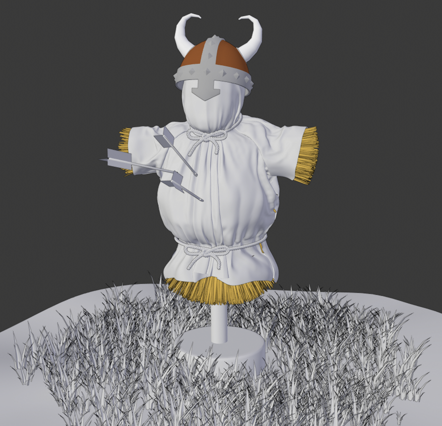
While we work in 3D, we tend to use low-quality preview settings for the Viewport because it's easier to see the polygons and it keeps our computers running fast while we work. So far, we have been working with low-quality preview settings, so our Viewport looks like this:
Now that we've finished making edits to the Viking scene, we can change a few settings to get a high-quality final image. A high-quality render needs a nice set of lights. Remember the Lights collection in the Outliner? Well, it's time to make it visible:
- Find the Lights collection in the Outliner.
- Click on the grayed-out eyeball icon to the right of the Lights collection.
Good – we have some lights, but a bunch of ugly lines appeared in the Viewport. These lines are part of a feature called Overlays. Overlays include everything from grid lines to selection highlights. They are helpful for modeling, but they get in the way for rendering. Next, let's turn off all of the Overlays so we can get a clear look at our final image:
- Look at the header of the 3D Viewport and find the four circle-shaped icons in the top-right corner.
- Find the button to the left of the four circles labeled Show Overlays.
- Click the button to disable all of the Overlays in the Viewport.
There's one last thing we need to do, and this is the big one: we need to change the shading from Solid to Rendered to see what our finished scene looks like:
- Look at the header of the 3D Viewport and find the four circle-shaped icons in the top-right corner.
- Click on the fourth circle icon to activate Rendered shading.
And that's all there is to it. Our scene shouldn't look boring, flat, and gray anymore. Instead, we should have an image like this:
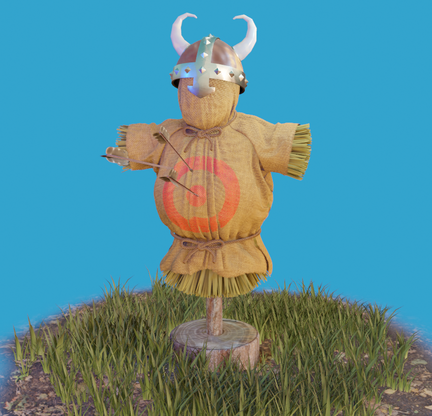
Much better, wouldn't you say? If you would like to, you can save this image by going all the way to the top bar and choosing Render | Render Image. Then, save the image to your computer. Congratulations on finishing your first Blender 2.8 project!
Summary
Wonderful! We've covered a lot of ground and you've edited your first model. We learned how to use the Outliner to organize the objects in the scene. We've built some familiarity with the 3D navigation controls. We also had a quick look at Blender's new Toolbar. Finally, we practiced basic transformations using 3D objects and components.
After doing all this, we edited a provided model with some of the most common modeling tools, such as extrude, and we learned how to select edge loops.
In the next chapter, we will learn how to start a project from scratch by making a time machine! We'll take what we learned while working on the Viking Helmet and expand on that knowledge using many more tools and workflows.