


So, you've successfully modeled an awesome character in Blender. After hours of careful and detailed work you have built a very appealing protagonist with a good topology for your next animation, but there's an issue: how do we make it look more life like, and also, how do we make it move?
Since a character model can be made of thousands of vertices, moving them individually across the 3D space is virtually impossible. We need an easier way of moving our models, and this way is called rigging.
Rigging is the process of creating a series of controls (the "Rig") to deform another object, which is often a character mesh. It involves creating special objects that move selected groups of vertices at once. This is the principle behind Skeletal Animation, where objects called "bones" are used to control parts of our models.
In Blender, there is a special object called Armature , which can be described roughly as a set of related bones that are used to control a mesh. To use an analogy, bones are for armatures as vertices are for meshes. Armatures can be added within the 3D View by pressing Shift + A and choosing Armature | Single Bone on the menu. Similar to meshes, armatures also have an Edit Mode accessible through the Tab key, where you can add, change, and remove bones as you wish. Bones can also be linked, creating a chain of hierarchically related bones.
Rigging is often referred to as one of the most difficult subjects in 3D animation. When creating a character rig, there are many aspects that you have to keep in mind, and two of them should be observed as major guidelines:
Finding an ideal balance between complexity of features and ease of use is the Holy Grail of character rigging. On one hand, if a rig is too simple it can be harder for the animator to give the character an "illusion of life". On the other hand, an extremely complex rig can be a nightmare: the animator should not require a tutorial to be able to start posing a character. It has to be straightforward enough to be used instinctively. Of course, a skilled animator should be able to achieve an amazing piece of animation even with a very simple rig, but the job of a character rigger is to make the animator's life easier.
Because every animation project has its own sorts of challenges and demands, there is no absolute right or wrong way to build a character rig. What we will see here are best practices that should apply to most situations. These recipes should be dealt with just as in a traditional cookbook: feel free to add spice to suit your personal taste.
When creating rigs for 3D characters in Blender, there is one mistake that is probably the most common of all, and it is also responsible for lots of headaches in the future: the orientations of the bone chains.
Every time we have to create a bone chain to allow our character to do a specific movement, some people (maybe in a hurry) often overlook this foundation of a good character rig. Since our characters and its bones live in a three-dimensional space, everyone familiar with 3D concepts should know that they are subject of the three world axes: X, Y and Z.
Along these concepts, we should be comfortable with the idea of "local" and "global" coordinates. Global coordinates are the ones relative to the scene: every scene has its Up or Down (Z axis), Left or Right (X axis), and Front or Back (Y axis) coordinates. Every object in a scene also has its own, or local, coordinates to allow easier transformations. To make an analogy with our world, "going East" would be the global coordinates while "turning right" refers to your local coordinates.
For instance, we should be allowed to bend a character forward regardless of its rotation and position relative to the scene. This "bending forward" would be too difficult to achieve using only the global coordinates; that's why we can use the local ones.
Using the concept of local coordinates, we have also to define some conventions such as which axis we are talking about when bending "forward". We have to pay attention to the sane organization of the bones, where a chosen local axis (for instance, local X) would be the same for all "forward" transformations, be it a finger or a knee. The character Otto, which is used throughout this book, uses the X local axis for the most common transformations, such as for bending the elbows and knees, closing the fingers, or bending the torso forward. This makes it easier to pose our character without having to worry about which axis you should use: if in doubt, use X!
Here we'll see how to create and correct bone chains in order for them to be more coherent and easier to manipulate.
Let's suppose you want a chain with three bones for a finger:
Open the file
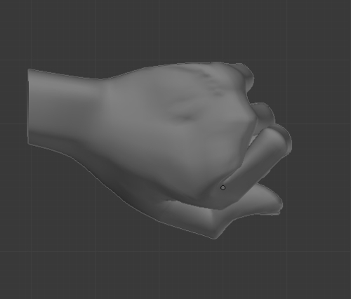
001-Orientation.blendfrom this book's support files. You'll see a hand model with four of its finger bones already set. I've let the ring finger for you to rig, like in the next screenshot:
Position your 3D cursor where the first finger bone should be created: select your mesh, enter the Edit Mode (Tab), select a vertex or group of vertices at the base of the finger and press Shift + S. Choose Cursor to Selected.
Go back to Object Mode (Tab), select the armature, enter its Edit Mode (Tab) and press Shift + A to add a new bone under the cursor location.
Note
In order to view better what we're doing, I've enabled the X-Ray and Axes display modes, in the Properties panel, under the Object Data tab.
Now you just move the tip of this bone until the finger's first joint and extrude the bone two times, right? WRONG!
Extruding bones is just what one would normally do in order to create a bone chain, but that brings to our new bones some unwanted rotations.
Select the tip of your bone and move (press the G key) it until the tip of the finger, as seen in the next screenshot:

Select your entire bone, open the Specials menu (press the W key), and choose Subdivide. Select one of the bones and repeat this process.
Move (press the G key) the joints to the appropriate places of the finger, and the orientations will be consistent. Note that the X axis of each bone is always pointing toward us, while the other bones on the hand have their Z axes pointing up. We need them all consistent.
Select the bones you have just created, press Ctrl + R, and type 90. This will correct their rotations, making their Z axes point toward us (check the Axis conventions section at the end of this recipe to know more about this).
Select the hand mesh, hold Shift, select a bone, and press Ctrl+ P. Choose With Automatic Weights to get a basic deformation on the hand.
Now you can rotate the bones under their local X axis (R + X + X) to see what happens.
Note
When you tell Blender to rotate (R), move (G), or scale (S) an object, you can use some key modifiers to tell it in which axis that transformation must happen. If you press X, Y, or Z one time, you're telling it that one of these global coordinates must be used. If you press the modifier key twice (X + X, Y + Y, or Z + Z) you're demanding that the transformation happen regarding that local coordinate.
When using a correct bone orientation upon its creation, you avoid the need to correct the armature later. The orientation of the bones is often overlooked, and problems at this stage will be painfully noticed on later stages, when the animator tries to move the bones in a coherent way.
To demonstrate that, I've created the index finger bones with the usual "extrude" technique. Let's say the animator wants to close the fingers: this should be accomplished by selecting each bone and pressing R to rotate and X twice to select the local X axis. The next image shows the results of the previous action with the bones hidden, to demonstrate how the extruding technique on the index finger leads to unwanted results. We wanted to close the finger, not twist it like that. An animator would have a hard time trying to figure out which axis should be used for every finger. Talk about being counterproductive!
What if you have already created bone chains with this orientation disorder? Do you have to recreate everything from scratch? No, there's hope for us all. This process is just to avoid the need for correcting the bones later, by creating them with the right orientations from the beginning. This means we can adjust the orientation by hand at any moment.
You can always correct or define the orientation of a bone through its Roll value. In the Armature's Edit Mode, select the bone(s) that you want to correct, press Ctrl + R, and move your mouse. As with any transformation in Blender, you can use it along with Ctrl (to do it in steps of five degrees) or Shift (to get softer transformations).
You can manually view and set the Roll angle of a bone through the Properties Panel (press the N key), just below the Radius slider, as shown in the following screenshot:
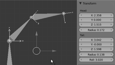
Another shortcut for automatically correcting the Roll value is Ctrl + N, which tells Blender to guess what the best roll angles are based on their Z axes, which will all point to the same direction ("Up" or the cursor location).
Another important thing to keep in mind when creating bones is axis conventions. It means you should always set the "front" of a bone to a given axis. This "front" is the default axis for a transformation, usually a rotation.
For instance, a humanoid character has some default movements, such as bending an elbow, knee, or finger. The bones for all these parts point in different directions, but you can set their roll values in a way that the animator's life becomes a little easier. A common approach is setting the X axis of a bone as the default transformation angle, so when the animator wants to bend and elbow, a knee, or a finger, it's just a matter of using the X local axis for that. There's no need to wonder "what local axis should I use for this transformation?". In the case of our armature, we can select all the bones, press Ctrl + R, and type 90, so the bones' X axes point at us in the Front view.
This way you get consistence throughout your rig, which is a must in professional workflows. I've seen rigs where different fingers in a hand required a different default axes for bending. A nightmare!
A very cool way to add new bones and chains is by using the Rigify add-on which comes bundled with Blender 2.5. You can enable it in the User Preferences Window (press Ctrl + Alt + U), in the Add-ons tab.
With this add-on enabled you can add predefined bone chains for body parts or even a full human body. The great advantage is that you don't need to worry about names or orientations, since they come configured. You only have to worry about correctly adjusting the preset chains to the proportion of your character mesh.
Chapter 5: Controlling fingers
A useful approach when building rigs is to create more than one bone chain to accomplish different tasks. The idea behind this is to not overwhelm you with so many functions attached to one single bone, making the rig easier to understand and modify.
It is useful to separate the bone chains by their main functions to make things easier to manage: one chain that will only deform your character's mesh, one for creating Inverse Kinematics (IK) controllers, another for Forward Kinematics (FK) controllers, interface, helpers, and so on.
By creating them separately, you can make changes without breaking things in your rig. If you stack all the functions and constraints on one single chain, a little change can make a real mess. By separating them you can also make your rig more appealing and usable by defining custom shapes, colors, and hiding bones that shouldn't be touched by the animator.
You need a mesh to be deformed by the bones you'll create. Open the file 001-Chains.blend
from this book's support files. It contains a tail-like mesh so you can follow this recipe to create separate chains, producing a scorpion-like movement.
Position the 3D cursor on the base of the tail, with a left mouse click in the 3D View, as seen in the next screenshot:

Press Shift + A and select Armature | Single Bone to create one bone which extends from the base to the tip of the tail. Enter in Edit Mode (press Tab), select its tip, and move (press G) it to the tip of the tail.
Select the bone, press W, and select Subdivide. Repeat this two more times in order to get eight bones. Select each joint and move (press G) it so it fits the tail nicely.
Select all the bones (the A key), press Ctrl + R, and type 90 so their orientation is set with their X axes pointing towards us. The X local axis will be the default to the front or back rotation.
Refer to the recipe called Defining good orientations for your bones if in doubt. You should end up with something similar to the next screenshot, showing the front and side views:

Still in Edit Mode, set the bones' names using the Properties panel (press the N key). For their names, use a prefix such as
D_, which stands for "Deformation". That's the role of these bones: they're responsible for deforming our mesh. Good names can beD_tail.1toD_tail.8.Note
In Blender versions prior to 2.5, finding the name of a bone in the list displayed by the program could be a tough job, as seen in the next screenshot. Using prefixes are crucial to help you find the desired bone in a list and know its function without having to select it. With the arrival of Blender 2.5, finding a bone (or any object) by its name is much easier: just start typing in the appropriate field to narrow the selection options.

Now we're going to create the controller bone. This bone belongs to another "chain" of bones responsible for controlling the deformation ones. The controllers don't perform any mesh deformation by themselves. Although in this example this chain has just one bone for the sake of simplicity, more complex rigs can easily have dozens of them.
Still in the armature's Edit Mode, place your cursor just above the tip of the tail and press Shift + A to add another bone. Press Ctrl + R and type 90 so that its orientation is the same as the deformation chain ones. Define this bone's name as
Tail. The controller bones are usually named without prefixes in order to be friendlier to the animator, who will look out forTailinstead ofC_Tail.Disable the Deform option on the Bones tab in the Properties window, as seen in the next screenshot, so this bone will not perform any deformations on the mesh:

Now we're going to add constraints to control our deformation chain. Go to the armature's Pose Mode (press Ctrl + Tab). Then, select the bone Tail (which is the controller one), press Shift and then select the bone on the tip of the deformation chain,
D_tail.8. Press Ctrl + Shift + C to bring up the Constraints menu and choose Copy Rotation.This will make the bone on the deformation chain copy the rotations of the controller one, but you will notice that it will copy the absolute rotation (which is not what we want). To make this bone copy the transformation based on its own rotation, select it and go to the Bone Constraints panel, under the Properties window. Check the Offset option and select Local Space on the two drop-down lists, as seen in the next screenshot:

Apply the same constraint to all other bones of the deformation chain: select them and, lastly, the bone which has the constraint we want to copy. Go to the Pose menu on the window header and select Constraints | Copy Constraints to Selected. That will apply the same constraint to all bones of the deformation chain.
Still in Pose Mode, select the
Tailbone and rotate it. You'll see that all the bones on the deformation chain follow its rotation like a real tail, as seen in the next screenshot:
Since the animators wouldn't need to see or move the bones on the Deformation chain, you should select and move (the M key) them to another (and invisible) bone layer. I usually move my deformation bones to the last layer, so you can do the same for yours. You should now also turn off the X-Ray option for this armature, since it's no longer needed.
Lastly, select the Tail mesh, hold Shift, click on one bone of the chain, press Ctrl + P, and choose With Automatic Weight to make our armature object actually deform the mesh, as seen in the next screenshot:

By creating separate bone chains to accomplish different tasks, you end up with a very usable and organized rig, which is easy to animate and to configure, since each bone does only what is meant to do. This approach allows us to have a larger number of deformation bones to achieve softer results while still being simple to animate, having fewer bones to be controlled by the animator. This example showed how a scorpion-like tail can be controlled with only one bone, although eight bones build its structure.
The concept of separate bone chains will be discussed further throughout this book, notably when creating different chains to control arms, legs, torso, face, and eyes.
As your rig grows in complexity, you should use the bone layers that Blender offers you to manage the chains.
In some cases it is interesting to make a bone present on more than one layer. For instance, you may want to keep your main controller bones (limbs, head, torso) only on layer 1 and leave the detail controllers (facial expressions, fingers, eyes) on layer 2. But there are other bones which act only to enable and disable features of your rig, such as the ability to stretch limbs or switch between Inverse and Forward Kinematics (more about this in the recipe Making an IK-FK switcher).
These "general rig properties" should be present on both layers 1 and 2. To accomplish that, select the desired bone, press M to bring up the layer selection menu, hold Shift, and click on all the layers that you want those bones to belong to.
And always remember to use prefixes for your chains in order to find what you want quicker. You can use D_ for deformation bones, IK_ for Inverse Kinematics bones, FK_ for Forward Kinematics chains, T_ for target bones, M_ for mechanism, and so on. There's more on these uses in later recipes.
Not only do we need to create rigs that work, but they also need to be usable for the animator. Blender offers us a property for the bones called X-Ray, that allows us to view the bones from any angle, regardless of the mesh it deforms. It can be useful sometimes, notably when editing the bone chains, but using X-Ray in more complex rigs can confuse the animator. Take a look at the clutter in the next screenshot, where all bones of our character Otto are visible and with X-Ray enabled:

As we mentioned at the beginning of the chapter, a rig must be visually simple and intuitive, so anyone without prior guidance can start moving the character without trouble. It is possible to change the default shape and color of your bones in Blender, making your rig much more usable and intuitive.
Creating custom shapes and colors for your bones in Blender is easy, and we'll see some good practices for your rigs. You can use any chain of bones in Blender.
Open the file
001-Legs.blend. It has two chains of three bones indicative of two legs of a human, as you can see in the next screenshot. We're going to make shapes for all the bones, and we'll make the bones of each leg a different color:
In Object Mode, create a single plane through Shift + A | Mesh | Circle. On the Operator tab, in the Tool Shelf (press the T key to open it), change the values of Vertices to
8and Radius to100.In the Properties panel (press N), set the name of this object as
SHAPE_Leg. Get in Edit Mode (press Tab), select the two vertices positioned over the X axis, and make an edge (F) between them. This would make a line to divide the octagon in half, similar to the one in the next screenshot:
Go back to Object Mode (Tab) , select the armature, and enter into Pose Mode (Ctrl + Tab).
Select Thigh.L and go to the Bone tab in the Properties window. Under the section Display, click on the field called Custom Shape and select SHAPE_Leg. Check the box called Wireframe , which will make your custom shape always be drawn in a more pleasing way, regardless of your current viewport shading. The next screenshot shows these fields:

You'll see that your bone will change from the default octahedron to the shape you just created. But you'll also notice that the rotation and position of the shape don't help much, since we need it at the middle of the bone and perpendicular to its direction. The next screenshot shows the problem:

Select your shape object again, enter in Edit Mode (Tab), select all the vertices (A), and rotate (R) them 90 degrees in the local X axis. You'll see that the bone shapes update automatically. To fix the position, making the shape stand about half of the bone, move (G) the selected vertices in their local Y axes until you are happy with the result. Still in Edit Mode, resize (S) the shape to achieve a reasonable size in your rig. The next screenshot shows the result:

Now you can use the same shape for the
Ankle.Lbone, using the Display section in the Bone tab under the Properties window.Repeat the same process and create another shape for the
Foot.Lbone: be creative and make a bi-dimensional shape of a foot. Name itSHAPE_Foot.LRepeat everything for the other leg and you should end up with something similar to what's in the next screenshot (I've created a simple character mesh to make it easier to see):
Now, the colors! We can use them to distinguish the bones in various ways: a color for the left limbs and other for the right ones, a color for IK and other for FK and so on. The important here is to make it easier for the animator to visually understand the difference between bones. Let's make the left ones red and the right ones green.
Select the left leg bones and press Ctrl + G. Choose Add Selected to Bone Group. This will create a new group of bones called just Group.
Go to the Properties window and select the Object Data tab. Under Bone Groups, you'll see a group called Group. Select it and change its name to
Leg_Lefton the Name field.Under the Color Set list, select 01 – Theme Color Set and click on the Assign button to make these bones red. Repeat the task for the bones on the right-hand side leg, choosing an appropriate name and selecting the entry 04 – Theme Color Set to make them blue.
Note
The next screenshot shows our rig with shapes and different colors applied along with the settings on the Properties window (the color images can be downloaded from the publisher's website or viewed in the digital version of this book). The file
001-Legs-complete.blendhas our finished recipe for your reference.
By setting custom shapes and colors for your bones, you can offer a much more intuitive interface for your controls, making the task of animation easier. You should create shapes that are larger than the mesh deformed by the armature, so that you can see the bones without using the clutter caused by the X-Ray property.
You should look for shapes that are simple and that show information about the control. In our example, we created an octagon with an edge through its middle. This edge shows visually the local X axis of the bone, making it easier for the animator to understand the default transformation of it. Feet, hands, and eyes controllers are often made using figurative shapes similar to the one in this example.
Along with getting an organized 3D View, you should also be able to easily manage your entire scene. Blender has a special type of window, the Outliner, which allows us to see every object in our scenes organized hierarchically. But the Outliner alone doesn't do all the tricks: you have to create and name your objects properly in order to stay organized.
The Outliner is a great tool in Blender to see the hierarchy of objects in your file. But when you create a rig with lots of custom shapes, the Outliner list can easily become full of objects you won't use. To remove the clutter of it, it's recommended to create an object (normally an "Empty" named "Shapes") to be parent of all Shape objects. This way, you can easily browse on the Outliner without dozens of shape objects. It's also useful to make this Empty object child of the Armature object, so all shapes are hierarchically related to the rig.
To prevent these objects from showing up in your render, a good practice is to select them all (A), move (M) them to the last layer and hide (H) them from your scene. The next screenshot shows the Outliner of this recipe's scene. Notice that the shapes are hidden (the disabled "eye" icon) and will not be rendered (the disabled "camera" icon):

Chapter 1: Get Rigging
The ability to create bones that deform a mesh is great, but that alone doesn't solve all our rigging problems. Some may argue that it's possible to create perfect deformations in every movement of your character just with lots of extra bones and even more detailed weight painting, but that's too time consuming. We want our rigs ready to be animated in a short amount of time. We care about our character looking good on screen, not the purity of the technique.
That's why we can solve some trickier rigging problems with corrective Shape Keys. Shape Keys are saved states of our character's mesh, with the position of each vertex stored in the computer's memory. We're going to create some custom deformations in our character to correct specific issues caused by our rig. The example will take care of one of the most common source of deformation problems: the bending of arms.
Open up the file 001-ShapeKeys.blend from this book's support files. You'll see an arm with two bones already set to deform the mesh. Try rotating the forearm on its X local axis for 130o. You'll notice that the vertices located near the elbow don't deform like a real arm would: there are noticeable intersections and the biceps should be contracted.
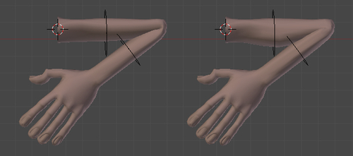
Even with the feature called Preserve Volume in the Armature modifier panel that uses the dual quaternion method to deform meshes in a more realistic way, some things such as muscles and specific skin deformations still need to be fixed manually. We're going to create a Shape Key here to act as the extreme deformation of this mesh when the character bends its arm to the maximum angle of 130o. Look at the next screenshot to see the before (left) and after the driven corrective Shape Key, where the biceps muscle gets contracted and the skin gets compressed between the arm and forearm.
Keep the forearm bone rotated on its X axis for 130o. Select the mesh and enter Edit Mode (Tab). You'll see that the arm goes back to its original position, as seen in the next screenshot:

We can tell Blender to keep the armature's deformation on the mesh while we edit its vertices, so that it's easier to create the corrective Shape Key.
Go to the Modifiers tab under the Properties window and locate the armature modifier. Next to the eye button, enable the one with the tooltip Use modifier while in edit mode. It will bring us another button next to it. Enable it too. Now we can edit the mesh after the deformation performed by the armature. The following screenshot shows the arm with our desired behavior and the Armature modifier panel with the highlighted options:

Go back to Object Mode (Tab), go to the Object Data panel under the Properties window, and find the section called Shape Keys. Click twice on the plus sign to create two Shape Keys: one called Basis, which is the base state of our mesh, and other called Key 1, which is the one we will work on.
Change the last Shape Key name to
Arm_Left. This is important when dealing with complete characters and lots of Shape Keys.We're going to use both the sculpting tool and the Edit Mode to build our corrective shape. In order to be able to work on a Shape Key in Sculpt Mode, we have to pin this shape.
With the Arm_Left key selected, click on the pin icon, just below the Shape Keys list. You should disable it when you're done sculpting. The next screenshot shows the Shape Keys section and the pin button highlighted:

Sculpting in Blender is pretty straightforward: select the mesh, pick Sculpt Mode in the 3D view mode list on the window header, and start sculpting the mesh. Under the Tool Shelf (T) you can select the appropriate mode of sculpting, such as Inflate, Grab, or Smooth, for instance. Use the Inflate tool for growing the biceps, such as in the following screenshot:

Since not everything will look right just with sculpting, disable the Pin button for the Shape Key you've enabled at step 5, enter into Edit Mode, and tweak the vertices until you're happy with the result of the arm bending shape. Go back to Object Mode when you're done.
Now comes the magic part: now that you have two shapes for your arm, we need to set a driver, so the rotation of the forearm bone on its X local axis triggers the morphing between those keys.
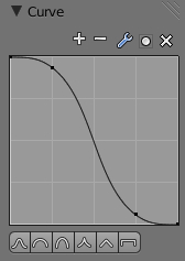
Below the Shape Key's name in the Object Data tab is a slider called Value. Right-click on it and select Add Driver. This will turn the slider into a pink color, which is how Blender shows you that this channel is driven by another object, expression, or property. The next screenshot demonstrates that:

Open a Graph Editor window to set up the forearm bone as the driver for this shape. Select Drivers from the Modes list in the header.
On the left panel, click in Value (Arm_Left) in order to see the pink line in the editor. On the Properties (N) panel, leave the driver type as Scripted Expression and change the Expr value to
var.In the box just below the Add Variable Button, leave Transform Channel on the first item; select Armature from the Ob/Bone selector and also the bone forearm in the box that will appear after choosing the armature; select X Rotation in the last list and check the Local Space box. This will tell Blender to take into account the local X rotation of the forearm bone to control the blending between the Basis and Arm_Left shape keys.
Rotate the forearm bone on its X axis to see the transformation. The biceps and skin get changed when you rotate the forearm, but the transformation happens earlier than we would expect.
To fix that, look for the Generator box inside the Modifiers section on the Properties panel. Change the Y value to
-1so that the blending between the Shape Keys starts only when the arm bending is closer to its final position. The next screenshot shows the driver and its values set:
The file 001-ShapeKeys-complete.blend
has this finished recipe for your reference.
Using a basic rig as starting point, you move the bones around and look for strange deformations, which would occur mostly in joints. When you find such deformations, its time to use them as a base to build new Shape Keys that correct the mesh in such situations. By using drivers, you can use the same bone values that caused the bad deformations to trigger the corrective Shape Key.
In this recipe you've learned how to create simple drivers in Blender. You'll notice throughout this book that most rigging features rely on them at some point. Fortunately they are not difficult to create.
The use of drivers in Blender 2.5 changed significantly from previous versions. Now, almost every property in Blender can be animated, driven, and used as a driver for other properties. It's just a matter of right-clicking over the property that you want to control and selecting Add Driver, then setting it up on the Graph Editor window. You can even make complex drivers using scripted expressions that can take into account more than one property and math expressions, for example.
Chapter 4: Adding expressions using Shape Keys
When creating rigs, we often face situations where we need to alter between two states or properties. The most iconic case is to alter from Inverse Kinematics (IK) to Forward Kinematics (FK) back and forth for a limb.
Forward Kinematics is the default state of regular chains of bones. When you move, rotate, or scale a bone in FK mode, all of its children bones inherit the same transformation. Therefore, we can say that the movement of a chain of bones in FK is driven by its base bone. It is often used for arm controllers when the character does not have its hands on a fixed position (such as doing push-ups).
Inverse Kinematics, on the other hand (no pun intended), works the opposite way: the movement of a chain of bones in IK is driven by its tip. It is often used for leg controllers, when the position of the foot bone drives the leg bones above it, and for arm controllers when the character does have its hands on a fixed position.
Since we may need to alter between IK and FK for an arm, for example, we can create specific controls to achieve that. These controls are normally made with bones that don't deform the mesh with some custom shapes applied to them.
Open the file 001-IK_FK_Switcher.blend
from the book's support files. The file has an arm mesh with three chains properly named and grouped: one for the mesh deformation (green), one to act as the IK chain (blue), and another for the FK chain (red), as we can see in the following screenshot:
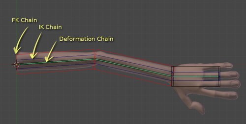
The three chains have the exact same position, scale, rotation, and orientation on the 3D scene. This is crucial to make our setup work as expected.
There is also a fourth chain with only one bone to act as the switcher interface. The bones are presented in B-Bone wireframe visualization with X-Ray enabled, which allows us to view them through the arm mesh and with different widths, since they are all on the same position.
Each bone on the deformation chain has two Copy Rotation constraints applied to it: one pointing to its relative bone on the IK chain and other to the one on the FK chain.
Note
Constraints are restrictions applied to objects or bones. There are currently more than 20 types of constraints built in Blender with a variety of purposes. The Copy Rotation constraint used here is pretty straightforward: the constrained bone (on the deformation chain) will copy the rotation of a target (a bone on the IK or FK chain). To add a Copy Rotation constraint to a bone in Pose Mode, first select the target bone (the one which will have the rotation copied), hold Shift, select the bone which will receive the constraint, press Ctrl + Shift + C, and choose Copy Rotation on the pop-up menu.
The constraints on each bone act in opposite ways, so we need a way to alter their influence in order to make only one operational at a time. We're going to use the switcher bone to drive the influence of each constraint: when the IK chain has full influence over the deformation chain, the FK will have none, and vice versa.
Select each of the green deformer bones and take a look at the Bone Constraints tab in the Properties window. You'll see that each bone has two Copy Rotation constraints already set: one for the IK chain with an influence of 1, and other to the FK chain, with zero influence. If you move the bone called IK_hand, you'll see that the green chain will follow it properly, while the FK chain in red stands still, as shown in the following screenshot:
Select the bone D_arm and go to its Bone Constraints tab under the Properties window. Under the first constraint, named IK_arm, right-click on the Influence slider and select Add Driver as seen in the next screenshot. You'll see that the Graph Editor window above the 3D View gets updated and the Influence slider turns into a pink color:

Under the Graph Editor, click on the driver on the left-hand side panel. Its properties will be shown on the Properties Panel (N). Navigate to the Drivers session, leave it as Scripted Expression, and change the Expr field to
var.Below the Add Variable button, leave the first list value as Transform Channel, select the Armature object on the Ob/Bone field and the bone called IK_FK_switcher.
Since we need this switcher bone to act as a horizontal slider, keep the X Location value and just enable Local Space. The next image shows our driver set:

Go back to the Bone Constraints tab under the Properties window. Now, instead of creating the driver from scratch, let's use one of the new useful features in Blender 2.5: right-click on the pink Influence slider on the IK_arm constraint and select Copy Driver. Next, right-click on the Influence slider from the FK_arm constraint and select Paste Driver. Now, both constraints will have the same driver.
Since we need this FK driver to act contrary to the IK, head over the Graph Editor and click on the FK driver (named Influence (D_arm: FK_arm)). On the Properties Panel (N) at the right, you'll see that all values were copied from the first driver. Since we need an inverted mapping, just change the Expr field value to 1-var. That's all we need to do create the inverted driver. The next screenshot shows the driver setup values:

Note
Regular drivers act on an ascendant curve with linear mapping, meaning that a value of zero on the driver object will make the driven channel have the same value. When creating switchers, we need an ascendant and one descendant mapping. This way we can increase the amount of influence of one driver while decreasing the concurrent one. As a tip, leave your desired driver in the default state with a descendant mapping.
Now you should use the drivers set for the D_arm bone constraints as reference to the remaining bones on the deformation chain. You can use the process described in step 5 to copy the driver from the IK_arm constraint and paste it to the IK_forearm and IK_hand constraints. Do the same to the FK constraints and you're done. No need to change anything in the drivers values.
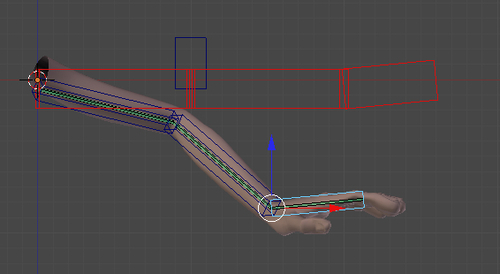
When you finish setting up the remaining drivers, move the FK and IK bones to different locations and switch the IK-FK slider: you'll see that the deformation bones (and the arm) alter between chains as you move the slider. The next screenshot shows the switcher in an intermediate position, where the deformation bones (and the arm) act under the influences of both IK (blue, medium width) and FK (red, fatter) chains.

The file 001-IKFK-Switcher-complete.blend has this complete example for your reference.
The logic behind a switcher is pretty simple, but the amount of chains and constraints may cause a little confusion. The deformation chain bones have two constraints each: one Copy Rotation with target to the FK chain and another one to the IK chain. The drivers are set in a inverse way: if IK has an ascending mapping on the Graph Editor, the FK must have a descending one. The controller bone does the rest: adding to one property reduces the opposite at the same amount.
The switcher that we've just created is basically an interface to control a feature in our rig, and the principle behind it can (and should) be used to control various other rigging features beyond IK-FK. As a rigger, you should be ready to use all features that Blender offers you to make your rig easier to use and understand.
With custom shapes and colors, we can create special interfaces as the slider used in this recipe. As we saw here, a single controller bone can drive more than one property in your rig.
In addition to these colors and shapes, user interface bones should also have constraints applied. In our example, the slider acts under a Limit Location constraint, which allows its transformation only on the local X axis, and just between the values 0 and 1.
More complex controls can act on some properties from its X location and other ones from its Z location, as drivers for facial controls.
Along with bones, your custom interfaces may have simple meshes to indicate the purpose of that control, such as the one on this recipe indicating the range and the IK and FK positions. It's a good idea to make such meshes un-selectable using the Outliner: just disable the pointer icon next to its name. This avoids unwanted selections, since the interface meshes act just as a visual guide. It's also interesting to make these interface meshes children of the Armature object to make them hierarchically related to it.
Blender 2.5 also enables us to add buttons and sliders to the application user interface through Python scripts. Although they are not difficult to create, they are beyond the scope of this book.
The Copy Rotation constraints are not the only ones to be used when creating IK-FK switchers. You can also add StretchTo constraints to the deformation chain bones in order to make them stretch and match the sizes of FK or IK chains without changing the models' volume.
The StretchTo constraints should be added on a similar way: two for each bone of the deformation chain. Each constraint should be mapped to the relevant bone of the IK or FK chain, and its influence slider must have a Driver pointing to the switcher bone. These stretching constraints should be used in conjunction with the Copy Rotation ones.
Chapter 5: Hands down! The Limbs Controllers
The process of weight painting is somewhat paradoxical: while it's one of the simplest in theory, it can be extremely difficult to get good results.
The complexity of getting good results will depend on how good your mesh topology is, and how you position and create your bones. Blender has an option to guess the bone weights when you bind a rig to a mesh, and it often bring us decent results. With this basic weights set, it's a matter of using the weight paint tools to define the deformation range of a bone into a mesh.
The logic behind weight painting is very simple: you pick a deformation bone and visually paint its influence on a mesh. Blender 2.5 offers some very neat features to allow us to turn this often tedious process into something quicker, such as allowing pressure sensitivity for tablets, mirroring weights, and custom brushes, just to name a few.
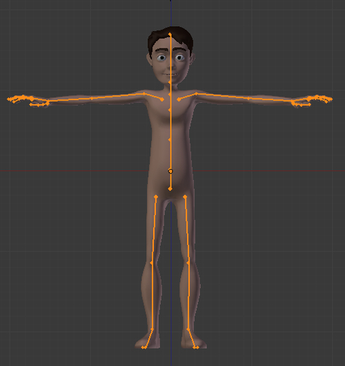
Open the file 001-WeightPaint.blend from this book's support files. You'll see the base mesh of my character Otto along with a basic rig in X-Ray mode. The armature is in Object Mode, so you can enter in Pose Mode (Ctrl + Tab) and try to move some bones. You'll notice that these bones aren't deforming the mesh yet, so the armature still needs to be connected to the mesh. The next screenshot shows the character and the armature:
Select the mesh, hold Shift, select the armature (or one of its bones, in the case the armature is in Pose Mode) and press Ctrl + P. Select Armature Deform With Automatic Weights. This will tell Blender to guess the influence of each bone on the mesh based on its size and position, painting the basic weights. This process is also often called Bone Heat , and (if you have created a good bone structure, matching the proportions of the mesh) brings us very reasonable results.
Enter in the armature's Pose Mode and try to move and rotate some bones. Notice that besides the automatic weights having being assigned quite reasonably, you may find some cases where the deformations need some adjustments.
Select the mesh again and enter in Weight Paint Mode (Ctrl + Tab). You'll see that the mesh color turns into a deep blue, and the last bone you selected in Pose Mode becomes selected again. The region affected by this bone gets colors in a gradient that goes from zero influence (blue) until 100% influence (red). The next screenshot shows different weight colors on the mesh after selecting the arm bone in Weight Paint Mode:

Note
If you want to change the default color gradient used in weight painting, you can do so by opening the User Preferences window (Ctrl + Alt + U). Navigate to the System tab, enable the Custom Weight Paint Range box and define your desired colors. To save this gradient for future sessions, press Ctrl + U to save the user preferences. Note that everything in your file (including meshes and armatures) will be saved too, so you might want to define a custom range in an empty file.
While in Weight Paint mode, you can still move the bones as you wish to test the influences you set in real time. Every time you select a bone, the mesh is updated to show the equivalent influence.
Make sure your Toolbox (T) is activated and select one of the painting tools available to adjust the weights on the Tools section. They act much like in 2D applications such as Gimp or Photoshop, allowing you to Add, Subtract, Blur, Darken, or Lighten weight colors. The Blur option, for example, is very useful to get smoother transitions on the weight colors.
If you use a graphics tablet, you can enable the pressure sensitivity on the Brush Tools section by clicking on the pointing hand besides the brush values. If you enable it, the sensitivity would pass values that go from zero to the value set on the slider. You can enable the sensitivity per value, so you can use a fixed value for size and a pressure driver for the brush strength, for example. The next screenshot indicates the options:

Note
The Auto Normalize option in the Brush section shown here makes sure that the sum of all weights applied to a mesh region is not greater than 1. This can be useful, but you may face problems if you're used to adding big weight values for different bones, since adding to one bone will subtract from the other.
To paint weight values on both sides of a character at the same time, enable the X Mirror option on the Toolshelf (T). You can paint the influences for the left limbs of your character, and the same weights will be applied for the right ones. This will work only when your bones have suffixes such as .L or .R to a proper identification.
When painting weights on the torso or head, for example, it is not possible to assign mirrored weights by using only X Mirror because there are no mirrored bones to take information from. This is when you should use the Topology Mirror option: it uses the information from the underlying edge loops on the mesh to apply mirrored weights based on the X axis.
To avoid painting on unwanted parts of the mesh, you can enable the Face Selection mode to select only the parts of the mesh that you want to paint over. Click on the Face Selection icon on the window header and select your desired faces as you would do in Edit Mode. The B and C selection keyboard shortcuts work as expected. The next screenshot shows the mesh with the Face Selection mode activated and an indication to the relevant icon on the window header:

The logic behind weight painting is one of the simplest: based on a color scheme, you paint the influences of a bone on the mesh. After using the automatic weights calculated by Blender, you have some pretty neat tools to refine the results and get a proper deformation on your characters.
Blender has some very useful tools to make the Weight Painting process quicker and easier. It is optimized for using with a graphics tablet, making the process even more intuitive, but it can be used nicely with a regular mouse.