


Setting Up and Configuring the 3018 CNC Machine
We have already covered some of the basics of computer numerical control (CNC), but in this chapter, we will focus our attention on a specific machine that is widely available from various vendors on multiple shopping platforms (Amazon, AliExpress, eBay, etc.). The 3018 CNC machine is a very basic, rugged unit, well suited to modification and upgrade, and its design has proven to be workable. You can choose to acquire a fully (or mostly) built unit, a kit to make one, or you can build one from scratch. I have tried all three approaches with similar results. However, before a purchase is made, some criteria and use cases should be established.
For this chapter, our objectives revolve around understanding the anatomy of a CNC machine, going through a primer on the selection of a suitable unit, and getting set up and running, as outlined here:
- Anatomy of a CNC machine
- Making the build-versus-buy decision
- Buying a pre-built unit
- Building your own unit
- Configuring, calibrating, and testing your CNC machine
Technical requirements
To operate your CNC machine, we should first discuss some basic requirements that will be needed to fully take advantage of your machine:
- A Computer-Aided Design (CAD) application: Unless you are downloading pre-generated G-code, you will need to either create or convert a drawing to G-code. There are several avenues for this. I use Tinkercad (a simple and free cloud-based CAD application) to import STereoLithography (STL) files or draw my own. From there, I save the drawing as an SVG file, which I subsequently convert to G-code using a conversion tool such as JSCut (http://jscut.org/jscut.html), which is also cloud-based. JSCut also allows me to visualize the G-code so that I can see how the cuts will proceed on the machine.
TinkerCAD is not your only option; there are other more sophisticated packages. However, in my years of garage tinkering, I have had little need for more complex (and possibly more expensive) tools. You can create an account on Tinkercad at https://tinkercad.com.
- A personal computer (PC): While there are solutions that cater to Linux-based or Apple/Mac computers, I have found that Windows-based software is the most prevalent and easiest to install and use. That is not to say a non-Windows machine is not viable, just that the offerings are fewer. The machine itself does not have to be a top-of-the-line machine. I run most of my CNC and laser machines using Intel i5-based machines with anywhere from 4-8 MB RAM and hard drives as small as 125 GB; most of the space is taken up by the operating system itself. The personal computer should have suitable USB ports (USB 2.0 and later) as you will need these to operate most machines as well as upload firmware.
You may also choose to run your machine using a Raspberry Pi single-board computer (SBC), which you would use as both the machine controller and the G-code sender. For this, you will need to install a suitable daughterboard (often called a hat) such as the Protoneer. We will not be exploring this approach in this book, but the concepts should not be too difficult to extend to something such as this. Add a small monitor and a keyboard, and your CNC machine is also a fully functioning (albeit dedicated) PC. Note: You will only require the PC to generate G-code and not connect it to your CNC machine if you have another means to send G-code to the CNC controller (such as an LCD controller with an SD card slot).
- Administrative rights to your PC: You should have the ability to load drivers and install software on your computer. If you are using a shared or work computer, you will need administrative rights from your system administrator to be able to prepare the computer for use with the CNC machine, including unblocking USB ports (for security reasons, many corporate PCs have their USB ports disabled or severely limited).
- An SD or Micro-SD card and suitable reader: If this isn’t built into your PC, SD card readers that plug into your USB port are easily available just about anywhere. I frequently use high-capacity Micro-SD cards that fit into an SD card shell, which is then inserted into a USB SD card reader. This allows me to move this storage media (the Micro-SD card) from PC to PC and from CNC machine to 3D printer to laser wherever an SD card slot is available.
- Arduino IDE: This is for compiling your own custom firmware. If you only plan to load precompiled firmware, you do not need this. Download the IDE from https://arduino.cc.
Note
As we deep dive into getting our machine set up and ready, you might consider heading over to https://howtomechatronics.com/tutorials/how-to-setup-grbl-control-cnc-machine-with-arduino/. This article breaks down CNC controllers further (many are Arduino-based) using a basic controller commonly available on Amazon. Look closely at the step calibration section because we will explore this deeper in this chapter as we get our machine ready.
- GRBL .hex file: You will either create this yourself (for a custom implementation) or download a specific vendor’s implementation of G-code Reference Block Library (GRBL). You can also download the baseline version from the GRBL GitHub repository at https://github.com/grbl/grbl.
- z-axis setting probe: While optional, I prefer to use this little tool (available from several vendors) to ensure I set the origin point (Z=0) for my z axis. The tool is cheap and precisely sets the origin point on the workpiece no matter what its thickness. If you have endstops on your machine, you may not need this as much because it is a simple calculation to determine where Z=0 as the top of the z-axis limit is a known value and is the distance from the tip of the carving/cutting bit to the worktable. The thickness of the wasteboard and workpiece is added and then subtracted from this height to determine where Z=0 is. I much prefer to let the machine determine this instead, which is why I used this probe, especially since I may have different-length bits and different-thickness materials. It just gets tedious to keep measuring the differences, so of course, I resort to automation. There is a great tutorial on how to use the probe at https://buildyourcnc.com/PrimeronHomingandLimitSwitches.aspx.
Anatomy of a CNC machine
Some of the basic components of a CNC machine were touched on in Chapter 1, The What and Why of CNC, but ahead of deciding which machine suits our purposes, we should know what the particulars are of each component. Here’s a view of a 3018 machine I built using some left-over frame parts from other projects and some 3D-printed components. The overall part count for the frame is very low, and most components can be obtained off the shelf. Most 3018 machines will look a lot like this:
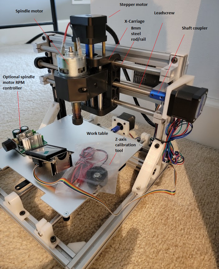
Figure 2.1 – 3018 front view
Looking at the labeled components in the preceding photo, we have the following:
- Spindle motor: We mentioned this component in Chapter 1, The What and Why of CNC. This is part of the toolhead and what drives the endmill bit. Think of it as nothing more than the motor out of a common hand drill with a chuck at the end of the drive shaft that will accept any of a variety of endmill bits. A review of commercially available machines may refer to this as a 775 Direct Current (DC) brushed motor. This is what many kits and pre-built machines come with. This particular motor came with a chuck already press-fit onto the motor’s drive shaft.
- Motor RPM controller: This optional item allows the user to externally control the revolutions per minute (RPM) of the spindle motor. Some older versions of GRBL can turn the spindle motor on/off and reverse its direction. After version 0.9, it became possible to use pulse-width modulation (PWM), a series of pulses turning the motor on and off and varying the duty cycle (how long the motor is running) to control the motor speed. In the absence of PWM, and when an upper limit for RPM is desired, the motor RPM controller comes in handy.
- Stepper motor: This motor is characterized by the ability to precisely control rotation, including holding the motor shaft stationary. These motors come in multiple designations (for example, NEMA 8, 14, 17, 23, and 34, which identify the size of the motor). Additionally, these motors have specific holding torque (the amount of force the shaft would need to experience to move it out of position) properties. Our 3018 machine uses three such motors, one for each axis (x, y, and z).
- Leadscrew: This is a helical precision screw that the stepper motor rotates to achieve motion in the x, y, or z axis. These also come in a variety of sizes (diameters and pitch), but for our purposes, we are using TR8 (8 mm diameter) leadscrews, which are very common. These have differing pitches (how much motion the leadscrew nut travels through each revolution of the leadscrew). For example, a 2 mm pitch means that the nut will move 2 mm with each rotation of the leadscrew. It should be clear that very precise movement can be made with these components.
- Shaft coupler: This connects the motor shaft to the leadscrew. Since the motor shaft is typically 5 mm in diameter and the TR8 is 8 mm, the coupler will have one end with a 5 mm bore and the other with an 8 mm bore. The coupler is secured to the leadscrew and motor shaft by tightening the screws on the side for a friction fit. A common problem with kit-built machines is having loose couplers, which interfere with the proper motion of the toolhead. Generally, couplers should be inspected after the build periodically to ensure they haven’t loosened.
- X-carriage: This carries the toolhead and the z-axis assembly. Unlike 3D printers, where the z axis is typically independent (CoreXY, D-Bot machines) or moves the x-axis gantry, many CNC machines carry the entire z-axis mechanism and move it left and right (in the x axis). This means this is a very heavy component, including the rails, z-axis frame, z-axis motor and leadscrew, and of course, the toolhead itself. z-axis travel is typically small and is represented by a negative number in G-code (where Z=0 is the surface of the material being machined).
- 8 mm steel rod: Not all CNC machines use these smooth, very durable rods for rails. However, many 3018 machines you will encounter use this as a standard for their motion systems. Other alternatives are linear rails, which are smoother, exhibit less wear over time, and are even more accurate (straight). They do, however, tend to be more expensive.
- Worktable: This is the surface on which you will place your materials to be machined. For my DIY machine, I used parts I already had in my parts bin, which included the metal platform from a long-defunct 3D printer. Many of the machines you will find online have extrusions in place of a worktable because those have slots that allow you to fasten clamps or even a wasteboard to the worktable (see Figure 1.1 in Chapter 1, The What and Why of CNC for another of my machines with an extrusion for a worktable). As the machine in Figure 2.1 was built explicitly for this chapter, we will later show some examples of how to secure workpieces of a wasteboard to the table.
- z-axis calibration tool: Because my machine is not using endstops (more on this later), we need to, at a minimum, determine where Z=0 every time we start a job (unless every piece of material we start off with is identical to the one before it). By setting Z=
0with this tool, we can be sure that our cuts (especially where we need to cut to specific depths, such as when drilling holes) are very accurate. This tool is not attached to a controller all the time, but rather is removed once the z axis is homed (that is, set to its lowest limit; in this case, Z=0).
A note on wasteboards
Wasteboards are consumables where CNC is concerned. Ideally, you would never need these because you will have precisely homed your z axis and your material to lie perfectly flat against the worktable, and your design ensures that your endmill will never touch the worktable. Of course, that implies a huge amount of trust in a machine, and no machine can be 100% trusted to perform exactly right all the time, every time. A wasteboard ensures that if there is an error, any damage is confined to it.
Now, let’s have a look at another view of the same machine. Figure 2.2 gives you a closer look at the same components we discussed up till now in this section, and we can see a few more:
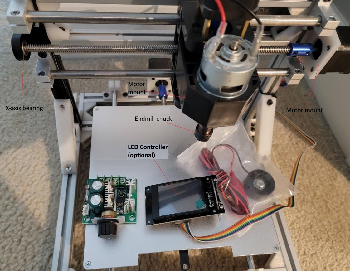
Figure 2.2 – 3018 top view
Notice how the screws are holding the worktable to the frame underneath (which was harvested from a dead 3D printer) and are countersunk into the worktable. This ensures that whatever is placed on top of the worktable lies flat and can consume all the real estate presented by it. Looking at this picture, you see the 775-motor mount. There are different-sized motors that dictate what you have: a mill or a machine. The same motor mount (if you look very, very closely, toward the front) has these small notches/grooves cut into the inside of the mount. These allow you to insert a laser toolhead (which is typically square-shaped) into the same mount whenever you want to switch from CNC to laser and back. On one of my other machines, I have fastened my laser head to the side of the motor mount so that I don’t have to keep swapping toolheads.
3D printer and printed parts for this machine
This machine makes extensive use of spare parts in my parts bin as well as 3D printed parts found on https://www.thingiverse.com. Most designs on this site are free to use for non-commercial purposes without prior permission. There are other sites where you can download models and designs for a fee (such as https://cults3d.com/en), but there is plenty to explore at Thingiverse and Thangs (https://thangs.com/). These two sites are where I usually go for part designs when I am building from scratch. Most if not all the parts I 3D printed can also be purchased at various online shopping sites such as Amazon. In my case, I purchased an X-carriage (which includes the z-axis assembly) because the 3D-printed equivalents proved to be unreliable for heavy-duty use on previous builds.
Looking at Figure 2.2, we can see the following components:
- LCD controller: This component is entirely optional, and allows for the operation of the CNC machine as a standalone unit. The computer is not needed to control the machine, only to generate the G-code, which can be copied onto an SD card and loaded into the controller.
- Motor mount: Stepper motors are secured here. In Figure 2.2, you see two of these for x and y, while the z-axis motor mount is largely made of brass standoffs. Because of the orientation of the motor, different forces act on the motor. In x and y, these are largely the same, but in z, you have more compression/tension loads owing to gravity and the need to pull and push a load with the leadscrew against or with gravity.
- Endmill chuck: This is just the part in which the bit is inserted. The bit is secured the same as you might in a hand drill. You hand tighten the nut at the bottom of the chuck, and that secures the bit in place (unlike a typical drill bit, however; endmill shanks are square to reduce the likelihood of the bit slipping in the chuck).
- x-axis bearing: On the 3018 there are two similar bearings. One of them is this one, for the x axis. While you could have a setup where this bearing does not exist, your x-axis leadscrew will wobble, which will lead to inaccuracies in movement. On desktop 3D printers, many manufacturers leave the z-axis leadscrews free on the non-motor end, and you would be well served to add a bearing there to prevent wobble. The other place you have a bearing such as this is on the y axis, which moves the worktable forward and backward.
Finally, let’s have a look at the rear of the CNC machine in Figure 2.3:
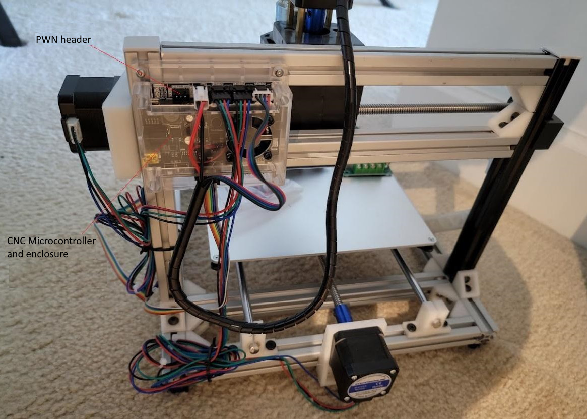
Figure 2.3 – 3018 rear view
In the preceding photo, you can again see the same familiar components as in Figure 2.2 and Figure 2.1. Notice the 8 mm rod mounts here. When I was building this machine, I ran out of the aluminum ones and I didn’t want to buy more (and wait for them to arrive), so I found a design online (and I did one of my own) and 3D printed it. Again, these are parts you can get online, no 3D printer required; I was just impatient to get moving. I printed eight of these in a few short hours.
In Figure 2.3, you can see the microcontroller mounted on the left. This unit has a USB port for connection to a computer so that G-code can be passed to it directly line by line. However, also of interest is the PWM header at the top left. If we had a motor that we could control that way, then we could use PWM to control motor speed. However, my criteria included laser support, and I wanted my laser to be controlled by PWM (so that the laser pulses instead of having a constant beam). The PWM header is therefore set aside for the laser toolhead I am planning for this machine later. The controller is encased in an enclosure with a fan over the central processor, and all electronics are powered by a laptop-style power supply.
Making the build-versus-buy decision
Now, some of you may be wondering whether to buy or build your own CNC machine. There are pros and cons to both options. I chose to build my machine because I primarily wanted to use spare parts I had from other builds that I knew might require some customization. I also wanted some freedom to add functionality that might be limited by an off-the-shelf kit.
However, based on what you want to do with your machine and how much time and money you have to spend, you can also choose to buy a complete machine.
To make the buy-or-make decision easier for you, in this section, I will highlight all the considerations that you may need to take into account, based on my personal experience.
Before we begin, I want you to ask yourself the following questions:
- What is the overall budget for the machine? Consider the cost of building as well, and factor in the amount of time you will spend in assembly.
- Which materials will be milled/machined?
- How thick will any given workpiece be?
- How large will the workpieces be? Is a typical 3018 work area enough? Is a desktop-sized unit sufficient, or would a workshop-sized unit be more suitable?
- Will a laser be added afterward? Or is a laser what is primarily desired? Will there be a need to work on curved surfaces?
- What size/power motors are available for the proposed budget? Are they sufficient for the workload anticipated?
- What kind of controller is desired? Is a commonly available purpose-made CNC controller such as the one in Figure 2.3 sufficient, or is more sophistication wanted, such as an MKS DLC board, mentioned under the How CNC works and when to use it section of Chapter 1, The What and Why of CNC? Is a touchscreen controller desired?
- What sort of features are desired/required? Are endstops important? What about a dust vacuum attachment? Can features such as that be added later? Are the added features widely available off the shelf or will you have to fabricate them yourself (for example, for my 3018, I will have to make my own mounts for the endstop switches)?
- Will it be possible to move the workpiece around, or is it more practical for all the axes to move around the workpiece?
The last question asked can dictate what sort of machine you choose. For example, BumbleBee (Figure 1.2 in Chapter 1, The What and Why of CNC) was designed to operate on workpieces that are too large to be moved by NEMA 17 motors, and my design criterion was to minimize the use of heavy-duty motors. Consequently, BumbleBee
sits on top of a workpiece, and the toolhead moves in all axes around it. This allows for the positioning of the whole machine over a specific piece of material that can be as large as I want it to be and then cut from it directly. On the 3018, you would have to cut your raw stock to fit on the machine first.
When you select a machine, consider carefully what your use cases are before you invest time and money into a specific unit. Still, even though we are focusing on the 3018 here, all the concepts apply to most other CNC and laser machines.
Buying a pre-built unit
Once a selection is made, don’t rush off and buy it just yet from the first vendor you see (for a pre-built unit). Instead:
- Comparison shop and be open to giving up a nice-to-have feature (such as a dust vacuum head) out of the box in favor of a substantially lower cost.
- Consider the frame materials used; not all 3018 machines are alike. Some use aluminum extrusions, some use thick acrylic panels, and others (the more expensive ones) use aluminum panels for the gantry. Considering the materials you will be milling, is a less rigid machine (with acrylic or melamine parts) acceptable? What happens if the acrylic cracks? Will you be able to replace it?
Building your own unit
If you are thinking of building your own unit, you must be even more selective. The following are some example considerations:
- What is the recommended holding torque for your motors?
- Can you locate the right leadscrews with the right pitch? Are you going to need a Delrin (a type of low-friction, high-wear-resistance plastic) leadscrew nut or a brass one? BumbleBee uses Delrin nuts, but my 3018s all use brass nuts. The difference is often dictated by design and expected wear.
- What power/RPM spindle will you use? Is a plastic mount sufficiently rigid, or will you need a metal one?
- If you are building a desktop unit, you will likely have a worktable that moves. If you are building a unit with a larger work area, the entire gantry will have to move along y. Are you going to use belts, and is that motion system likely to have binding problems (I have seen some of the belt-driven systems get hung up because the belt gets trapped in the frame extrusion slots and wears down very quickly, or loses tension very easily)? Look at the motion system closely and play the devil’s advocate to see where the potential for wear is and whether you will be servicing the machine more often than you would like.
Regardless of whether you are building or buying your CNC machine, you will have to go through some setup processes before confidently working on a project.
Configuring, calibrating, and testing your CNC machine
Once you have fully assembled your machine, you will need to set up the parameters that control it, prepare it for calibration, and run some tests before you put it into operation.
If you built your own machine from an open source design, you might also have downloaded a copy of the firmware for your microcontroller. In many cases, the controller already has firmware on board, but it may be obsolete; so, the first thing to do is determine whether you have the latest version installed. If you purchased a pre-built unit, then check with the vendor to make sure the firmware is up to date.
For off-the-shelf units/kits that come with everything, do not immediately overwrite the existing firmware with a generic version unless that is what is there already, since some vendors create their own flavor. Check with the vendor first to ensure you have an up-to-date installation, or, if you want to install your own, get whatever configurations they may have added and save yourself the headache of having to figure them out on your own. A great source of information is Endurance Lasers, which publishes a bunch of useful articles on CNC and lasers. For GRBL command information, you can go to https://endurancelasers.com/an-important-things-you-need-to-know-about-grbl-firmware/. You can also download the latest version of GRBL from its GitHub repo at https://github.com/gnea/grbl.
A machine built from scratch is going to require you to set up things such as the spindle motor thresholds, the step measurements (how much movement you get from each turn of your leadscrew), the limits of your work area for your machine, and much more. There is even a link to a firmware image just for 3018 machines. For some of my self-designed machines, I started with default settings, attempted to cut a rectangle of known size, and then measured what the actual rectangle dimensions were and adjusted the numbers until the rectangle was cut to match the dimensions of the design in the sender program.
Step calibration
Let’s touch on how to determine the settings for your leadscrews (there is a similar calculation for belts, but since the 3018 uses leadscrews, we will use this). Obviously, if you are buying a kit, you will not have to do this. As mentioned before, your controller may have firmware already loaded that has some default value for x, y, and z. Your machine may be set up for imperial or metric measures. The vast majority of machines I have encountered have been metric, so the example we will go through in this section will be using calculations based on the metric system. Let us first gather some information that we know about our motor:
- Number of steps per revolution: This is defined in the specification of the motor and should be published in a pamphlet that comes with it. Let’s go with 200 steps per revolution for our example.
- Number of microsteps: These are defined by the stepper driver on your controller and indicate the number of microsteps per full step. This number should be published with the specification of the driver for your controller board. If you cannot find it, you can assume a number, run the calculation, do a test, check the outcome, and then adjust this number accordingly. Some of the offline/LCD controllers allow you to adjust this value for each axis. For the sake of argument, let’s use 4 for the number of microsteps. This means that each revolution of our motor will require 200 x 4 (or 800) microsteps per revolution of the motor.
- Leadscrew pitch: The common TR8 leadscrews come in varying pitches (measured in mm) typically denoted with a p. For example, TR8*8-2p means an 8 mm diameter lead with a 2 mm pitch. The pitch value indicates the number of millimeters the nut travels per revolution.
So now, 200 steps per revolution translates to 2 mm of travel per revolution, so we have 200/2 steps per mm or 100 steps per mm. This also translates to 400 microsteps per mm (800/2).
If you are compiling the firmware, you would be setting the values in the firmware code (for the z motor, for x and y, the same setting is defined by the axis) as follows:
#define DEFAULT_Z_STEPS_PER_MM 100.0
The GRBL command to determine what the current value is for z is $102. For y, the command is $101, and for x, it is $100. You can enter these in the sender program once you are connected to the machine to find out what the current firmware settings are.
If you don’t want to download and compile the source, you can enter the appropriate values in the terminal window of your sender software as follows:
$102 = 100
Now that we have determined the leadscrew settings, let’s look at how to load precompiled firmware and then make changes to the settings for our machine.
In the article from HowToMechatronics mentioned in the Technical requirements section, calibration is described in terms of using the wizard provided by the Universal G-code Sender (UGS) (see the G-code sender software section later in this chapter for an evaluated list of G-code sender applications) to set your steps. The onboard wizard starts with the default of 250 steps per mm and allows you to adjust this based on the amount of movement you see; for this, we will need a metric ruler with millimeter measurements. The process is fairly simple and involves the following steps:
- Start UGS and connect to your machine.
- Position the toolhead somewhere in the work area and make a note of that position. If you have an endmill bit in place, lower the toolhead with the z axis (using UGS) so that the endmill touches the work surface (use a piece of scrap wood on your worktable). Mark this location and raise the toolhead a few millimeters.
- Now, move your machine along the x axis using the X+ button. The toolhead should move from left to right 250 steps. Lower the toolhead again and mark this location.
- Measure the distance between the two marked locations. In the wizard, enter this distance. The software will then calculate the correct steps per mm for your machine for the x axis.
- Repeat the same process for y, pressing the Y+ button to advance in that direction.
- For the z axis, you will need to measure the height you move the toolhead with each press of the Z- button (note, not Z+ because raising the toolhead is considered negative in CNC since the workpiece surface is Z=0). Here, you simply measure the height from the worktable to the tip of your bit and again enter that value into the wizard.
Once you have entered those values and saved them into the firmware, your machine is largely ready (other than homing, which I will address in a later section when we begin testing and make our first cut).
Firmware flashing software
To get your version of GRBL on your CNC machine’s controller, you will need specific software. Loading firmware is called flashing and makes it possible to use a variety of tools. If you are building a machine from scratch, I encourage you to select a board that already has a bootloader (effectively a program in memory on the controller that allows you to load updates to the firmware). Without a bootloader, flashing firmware is a little more complex.
While there are many ways and tools to flash firmware, the following are two popular methods:
- Using XLoader: This is the most common method to load firmware but is only available for Windows. The downside of this little program is that it could hang up, wiping out the firmware on your board in the process. I have had it work fine on some PCs (Windows 10) and not on others. Frequently, the issue has to do with the communications speed (baud rate) at which your USB port can send data to your board. You will have to experiment here or ensure you know what the numbers are for your controller. You can download XLoader from GitHub at https://github.com/xinabox/xloader. Otherwise, the only thing you will need is the
XLoader.exefile in the ZIP file you download.The following is a screenshot of the XLoader interface:
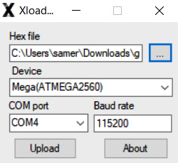
Figure 2.4 – XLoader interface
- Using LaserGRBL: This is not only a sender program but also has a built-in process for flashing firmware. I have used this program to flash firmware on both CNC and laser machines, adjust the firmware (stored permanently onboard the controller), and control some of my machines. Here is the main screen of the latest version I have. Note the menu option where GRBL can be uploaded:
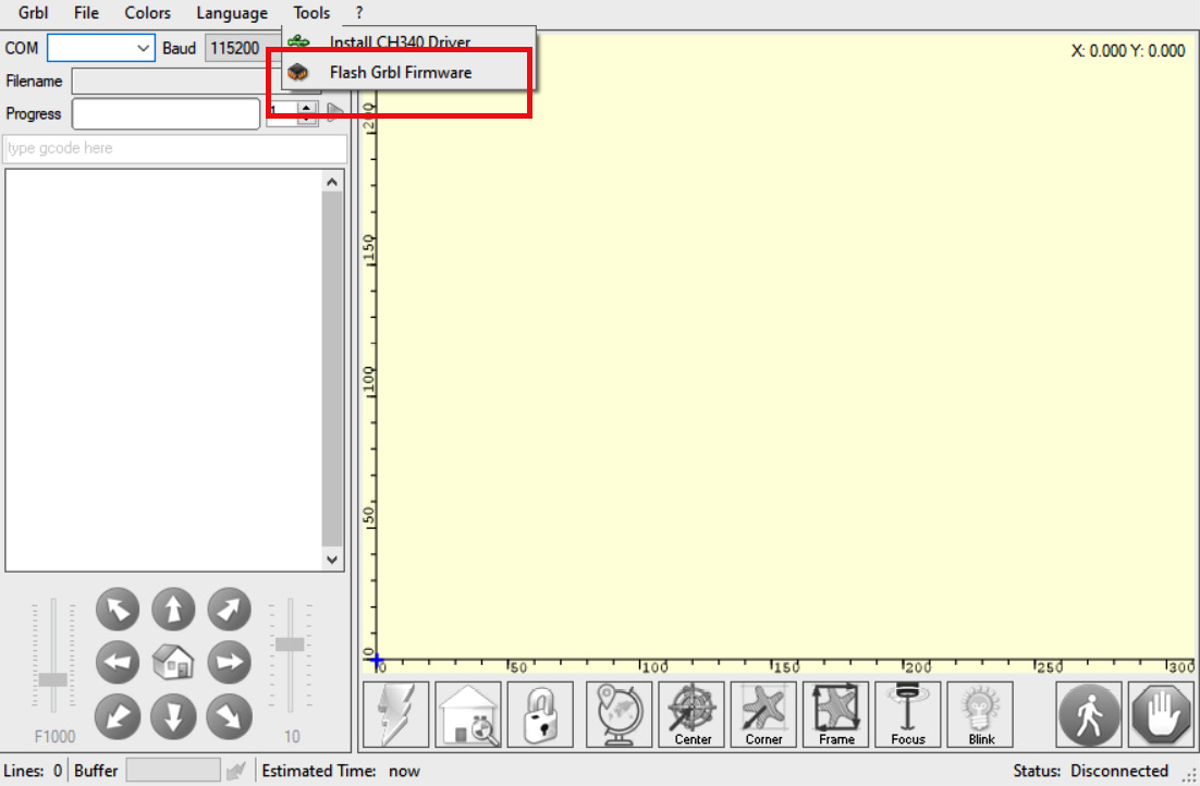
Figure 2.5 – Main screen for LaserGRBL
Once you select the Flash Grbl Firmware menu, you will be led to a dialog box that is very similar to XLoader’s:
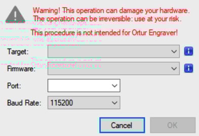
Figure 2.6 – GRBL loader dialog box in LaserGRBL
There are other ways, of course, including freely available versions of Benbox (another laser engraving program that allows for custom versions of GRBL to be loaded from the Benbox vendor), but I have found the two methods I have discussed easy to use. Also worthy of mention is T2Laser, which also allows you to flash versions of GRBL from a menu of available distributions. However, your mileage may vary here, especially if you have your own custom-compiled version.
Your precompiled GRBL firmware file will have a .hex extension. This is what you will need to provide to the firmware loader. You will also need to define the target COM port, represented by your USB port. I have noticed some loaders are not too comfortable reading the firmware file from network shares, so it is recommended to have the file loaded on the PC’s local drive somewhere.
Connecting a controller to a PC
Your CNC machine will appear as a USB device on your PC. I have had excellent success connecting various desktops and laptops to many devices and controllers with little to no issues. Frequently, the device driver is automatically loaded (depending on the nature of the controller). However, failing that, you may need to load the device driver, commonly referred to as the CH340 driver. The reason for the name is that this chip (the CH340) is a common component of Arduino boards on which most hobbyist controllers are based or are clones. Load this driver (it should come on storage media with your controller) if you are unable to get your PC to recognize the board. When I am working on a from-scratch build, I check connectivity and load drivers and firmware before the board is ever connected to the CNC machine itself. Once connected, a look into Device Manager (for Windows) will show you which port your controller is on (COM4, COM5, COM6, and so on).
It is important to pay attention to the baud rate once you are connected to your controller. Using an incorrect baud rate will cause some loaders to hang, and you will have to force close them and try again. The acceptable communication speed should be published by the vendor of the controller in their specifications.
Before we move on to looking at G-code sender programs, let’s briefly go over LCD controllers. There are many alternatives here, and how you connect depends on the boards you are using. If you are using a controller such as a Mana board, there is no provision to use an LCD controller, and you are limited to using a dedicated PC for the duration of your CNC operation. On the other hand, more modern controllers will have connectors, such as those you saw in Figure 1.6 in Chapter 1, The What and Why of CNC to add an LCD.
I am a big fan of the LCD controllers put out by MKS Base (or Makerbase). These come in a variety of sizes, with support for SD or microSD cards so that the LCD controller can stream G-code to your machine instead of your PC. Many of MKS’s products also include the provision for Wi-Fi to allow wireless control. Here is a photo of a 2.4” touchscreen unit I have set aside for my 3018. These units come in various other sizes, including 3.2” and 3.5”. When you purchase them, they may have the 3D printer firmware on them by default. However, MKS puts out CNC and laser firmware as well.
In Figure 2.7, you see that I have already loaded the CNC/laser firmware:
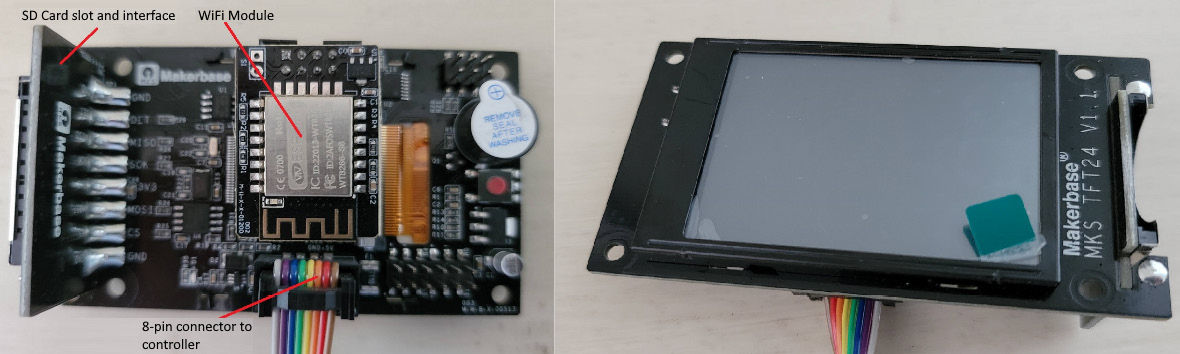
Figure 2.7 – The MKS TFT24 for my DIY 3018
The following photo shows you my FLSun Cube printer. Same LCD vendor, but a different model. The 3D printing firmware is FLSun’s modification of the baseline provided by MKS:
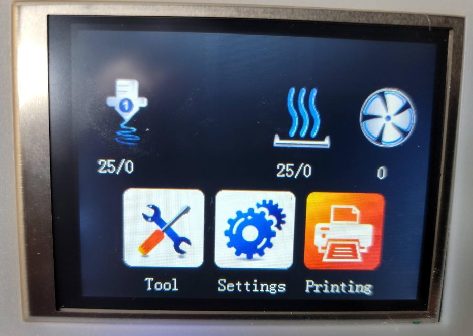
Figure 2.8 – Another TFT LCD with the default 3D printer firmware installed
Loading the firmware is very straightforward and requires the LCD to be connected to your controller and the controller connected to power. Prior to starting up, you load the desired firmware on an SD card and insert that into the LCD controller. When you connect power and the devices boot, the LCD automatically recognizes the firmware file and loads it. The great thing about this is that the LCD firmware will have most of the features to support upgrades, such as adding a laser, supporting endstops, and so on.
G-code sender software
Let’s review the various G-code sender programs and the ways of loading firmware onto your machine’s controller. Recall that we need senders to send the G-code to the controller because most small microcontrollers have limited memory capacity to hold more than a small number of commands. The other alternative is to use an LCD controller that allows offline operation, but you still will need sender-type software to generate the G-code file to load into the LCD controller, especially given the availability of calibration wizards such as the one in UGS. In this brief compendium, I list some of the more popular applications with as much focus on multiplatform availability as possible:
Alternatives to GRBL
While we are focusing our attention on GRBL in this book, you should also be aware of other firmware that is available, such as Maslow CNC, TinyG, Marlin, Repetier, and Klipper. For example, while Marlin is very common for 3D printers, it can be modified/adapted to run a spindle instead of a hotend (the part of the 3D printer that lays down melted plastic).
- UGS: This is one of the most common, easiest to use, and feature-rich applications. It is 100% free and is multiplatform, covering Windows, Linux, and the macOS world. It does support Raspberry Pi as the host platform as well, which means your CNC machine can have an embedded SBC PC, or simply be connected to one and make use of your machine’s onboard CNC controller. The other benefit is that you can also use its wizard to calibrate your machine (as discussed previously) and the ability to check the wiring of your motors. You can also configure your endstops or set soft limits (no physical endstops). Download it from https://winder.github.io/ugs_website/.
- OpenBuilds CONTROL: I like this fairly light application because it has the basic G-code sending functions but also includes the ability to flash firmware. As new versions of GRBL become available, you can update your machine using this software. If your PC is also on a network, you can also remote control your machine over the same network. This particular application has a huge following and can be used to control a CNC machine, a laser cutter/engraver, a drag knife, and a plasma cutter. Support for Windows, Linux, and macOS is available. Download it from https://software.openbuilds.com/.
- ChiliPeppr: If you prefer a browser-based application and can have a persistent web connection throughout your CNC machine’s run, then consider this application. ChiliPeppr not only is multiplatform but also supports multiple firmware platforms. You do need to install a small serial port JSON server to allow the application to talk to your CNC machine, but that makes for a very small footprint. Needless to say, you can use a Raspberry Pi, Linux, Mac, or Windows PC to run the machine. It does have limitations in that it can only handle 25,000 lines of G-code in its buffer. You can reach the application and download the JSON server from http://chilipeppr.com/ and go to the GRBL workspace at http://chilipeppr.com/grbl.
Other available applications include Candle, CNCjs, Easel (subscription-based), Ultimate CNC, and LinuxCNC. Consider these as well if you would like to explore alternatives to what has been presented previously.
In the laser world, I have had good experience with three applications. The first is T2 Laser (https://t2laser.wordpress.com/), which I have used to flash firmware on both laser and CNC machines and actually can be used to control both. T2 is paid software, and if you select it, you will need to decide if you are going to use it on more than one PC because the license can be tied to a PC. If you plan to use multiple machines, purchase the license that comes with a dongle that allows you to use different machines (albeit one at a time).
By far, LightBurn (https://lightburnsoftware.com/) has been my favorite (albeit paid) application for laser work. Finally, LaserGRBL (https://lasergrbl.com/) has proven to be a very robust application for my purposes.
You may also run across a software called Benbox. While commonly available with some laser machines, some units come with modified versions of GRBL specific to the board on the unit. I have occasionally resorted to Benbox to test my laser and flash GRBL but I generally don’t use it because of its limited features.
Running your first test cut
With your machine now set up and operational, it’s time to cut your first piece of material. Before we begin, we will need a wasteboard. This is a piece of material that we can make mistakes with that will protect the worktable from the cutting/carving bit should we need to cut through our workpiece. Make this out of a piece of any plywood or MDF that you can get at your local big-box DIY store. I like these to be at least 1/4” (6 mm) thick to ensure I have some leeway to stop a cut if it gets deeper than planned and to protect my metal worktable, and to drill holes to screw in clamps to hold my workpiece.
If you prefer, you can also buy wasteboards from places such as Amazon, but those are typically configured for worktables made of 80/20 extrusions, such as my machine in Figure 1.1 in Chapter 1, The What and Why of CNC. Those have countersunk holes to secure the wasteboard using T-Nuts. If you have a flat plate, as I do with my machine in the photos in this chapter, use strong binder clips to hold the wasteboard in place.
Place your workpiece on top of the wasteboard. You can secure it to the wasteboard in one of two ways:
- Option 1: Drill holes in the workpiece through and into the wasteboard and screw it onto the wasteboard directly. Make sure that your screws are countersunk so that they don’t interfere with the movement of your toolhead and that they are located outside the outermost boundaries of the object you will liberate from the workpiece. You will also need to drill a hole and put a screw through in a suitable location so that the part you cut out does not move around as it gets cut out of the workpiece. If you are only engraving to a specific depth, you don’t need to do this.
- Option 2: Use clamps that your machine may have come with to secure your workpiece. Again, place those clamps where the toolhead is unlikely to collide with them as it carves through your material. Once again, if your final product is meant to separate from the stock workpiece, you must secure it to the wasteboard so that it doesn’t come loose and mess up your cut.
The following is an example of one of those wasteboards you can buy on one of my 3018 machines. Note all the holes in it that are countersunk with T-Nuts as well as the holes for securing it to the worktable:
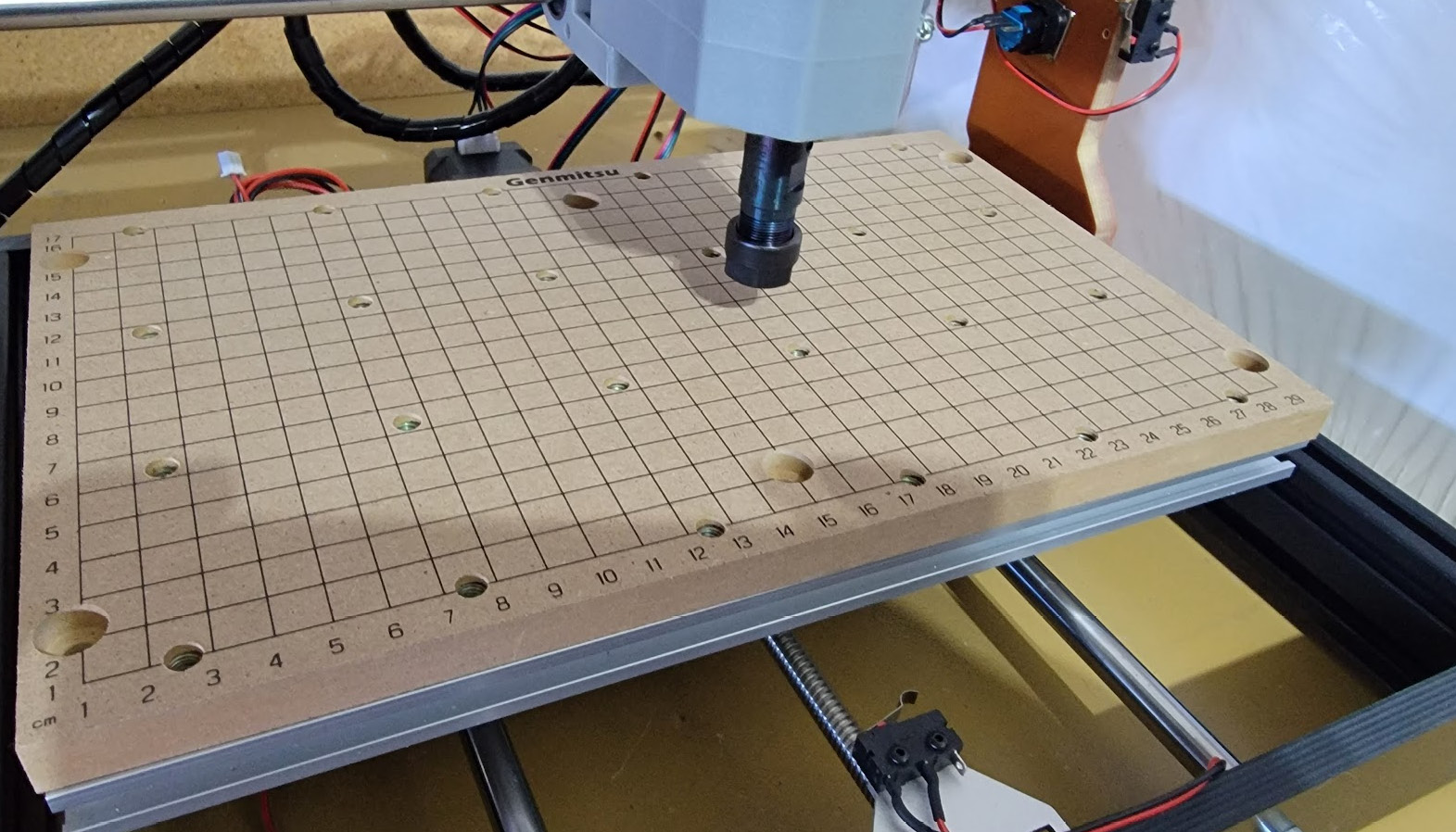
Figure 2.9 – A wasteboard on one of my 3018 machines
The final step before we make our first cut is to home our axes. Let’s start with the z axis. The following photo shows one of these probes that I use. The way the probe works is to complete a circuit when the carving/cutting bit’s tip touches the probe:
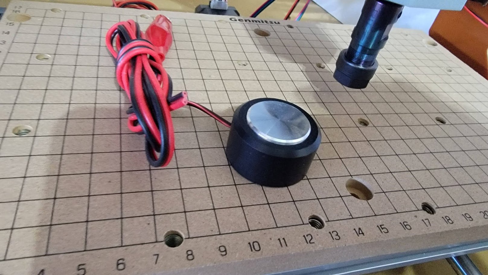
Figure 2.10 – One of my Z-probes for the 3018
The Z-probe typically comes with instructions, but fundamentally, you are connecting it to the controller (or if you are using an Arduino, to the A5 and GND pins) and probe header, and then you set UGS to set Z=0. There is a great video on YouTube that illustrates this far better than anything written: https://www.youtube.com/watch?v=PtJF8q3RrDo.
Next, set the X=0 and Y=0 points on your workpiece and, using UGS in the Machine Control menu, jog your axes to where you want X=0 and Y=0 to be and press the appropriate Reset Zero button.
This YouTube video also offers some additional detail on getting your axes ready: https://www.youtube.com/watch?v=A1zlL3q23HI. The presenter here uses a technique similar to how bed leveling is done on a 3D printer where Z=0 is set using a piece of paper. Something to keep in mind is that this is something you can’t really do as easily with some LCD controller firmware, which is why if I build a machine to be standalone, with an LCD controller, my preference is to have endstops to ensure the toolhead does not crash into the axes limits and I can home (set the origin) automatically every time. My DIY machine started out with no endstops but did end up with them just because it was far easier to calibrate.
With your axes set, it is time to run a test. I suggest you attempt to cut some basic shapes first: a triangle, a rectangle, and a circle. Using whatever design software you have, make these shapes, and set their depth to be smaller than the thickness of your workpiece so that you can just engrave the shapes. The easiest way to do this is to create the shape in your favorite CAD application and convert it to G-code. Load the shape in, generate the G-code, and then load the G-code into UGS (if that is what you are using). Start the spindle, execute the cut, and see the results. Once the machine is done, jog it back to its 0,0,0 location, stop the spindle if it is still turning, and turn off the machine so that you can inspect your results. Confirm the dimensions of your shape against what you intended them to be, and if everything measures up, you are ready to start doing some CNC milling.
Summary
In this chapter, we took a deep dive into what is needed to set up our CNC machine and prepare it to mill our workpiece. We also determined how to load firmware, calibrate it, and set the origin of the axes. Finally, we also learned how to prepare the necessary G-code to load into our machine. While we focused on a machine without an LCD controller, the only difference between using a sender program such as UGS and the LCD is that the LCD will require the G-code to be loaded onto an SD card and read directly from there. There would be limited functionality to reset zero on the axes, which then speaks to having endstops on your machine, something we will cover in greater depth when we get to upgrades.
Our next chapter will get into selecting our materials for milling, as well as the bits we need to use. We will also look into what and how various bits cut and when we should use them.