


Modeling the 3D Asset
Blender is an extremely powerful tool for creating 3D models for a variety of purposes and has increased in popularity over the last few years mainly because it is a free and open source program, which makes it accessible to basically anyone with a computer. It has been designed so that every step of the 3D pipeline can be carried out within the program itself. That’s why many people are starting to create assets for the metaverse using Blender rather than paid alternatives.
In this chapter, we’ll learn how to start creating your own original assets, as well as learning how to navigate through Blender’s interface and use its main modeling tools, using the modifier system to speed up the process.
In this chapter, we’re going to cover the following topics:
- How to look for good image references
- How to break down an object into simple shapes
- How to create a base shape to build upon
- Deciding on the level of detail necessary
- How to gradually add detail to the base shape
Gathering references
Before starting any work, it is crucial that you have at least an idea of how the final product will look, as this will guide every other step of the process. Aspects such as the asset’s style and materials are useful to keep in mind during the whole process. That’s where image references shine, as they clearly show us how much detail to actually add to our models and what the general shape we should aim for is, among other aspects, which will make our asset look believable and fitting.
What are good and bad references?
When looking for image references, we come across thousands of images with different properties such as resolution, brightness, and lighting, and in order to guide ourselves correctly and effectively, we should be able to distinguish between what is a useful reference and what’s not.
A good reference image should clearly show the shape, color, and material of an object in order to guide us correctly.
What to look for and avoid while looking for references
Generally, we’d want to avoid images with low resolution and bad lighting, which can flatten the shapes and “erase” detail. Photos taken with a light source located near the camera, for example, tend to flatten the shapes a lot, so it’s a good idea to avoid pictures taken with flash or amatewur lighting. Pictures taken in a studio, on the other hand, tend to have ideal lighting, showcasing most of the details of the object.

Figure 1.1 – Examples of bad and good references (images from https://www.pexels.com/)
From the preceding figure, we can notice several differences between the references: the bad reference doesn’t show the general shape of the object clearly, as it was taken from a bad angle, while the good reference makes it very easy to see the silhouette as well as the sides of the headphones.
The lighting in the bad image makes it even harder to distinguish the shapes that make up the object, and the harsher, darker shadows “blend” the sides of the headphones with their own shadow, which doesn’t help when defining the thickness of the headband. The lighting also prevents us from seeing the material properties, such as the surface bumpiness and roughness, clearly, especially in the cushions around the ear, as well as the plastic that makes the outer part of the headphones. The good reference, though, shows us the complete opposite: with clearer, brighter lighting and fewer postprocessing effects, it’s now possible to notice most of the details on the surface, such as how shiny each part is; the headband and cushion materials are now clearly noticeable as they appear to be made out of a leathery material, along with some less shiny plastic parts.
Another aspect to keep an eye on is the exposure of the image as this can also make it harder to see details, so avoid under- or over-exposed images (see Figure 1.2):

Figure 1.2 – Examples of good and bad image exposures (image from https://www.pexels.com/)
It’s worth noting that we should not work with one reference only, as this “limits” our view, so it’s very important to find a set of reference images from a variety of angles and different versions of the same object (unless, of course, you’re making a replica of a specific version), including of 3D models in your desired style, along with real-life pictures. PureRef is a good, free external tool, useful to organize the chosen reference images in a more concise way, though this is optional. Now, with a proper reference, we should be a nice guide to refer to throughout the entire process, which starts with blocking out the general shape of the asset.
Before we hop into making the actual headphones, though, let’s have a quick look at the viewport so that we can familiarize ourselves with the environment we will be working in further down the road.
A quick tour of Blender
The first time you open Blender, you might feel overwhelmed just by looking at the interface:

Figure 1.3 – Blender’s default interface
Let’s start with the bigger windows. The biggest one is the 3D Viewport, where you add objects, edit your models, and/or set up your scene overall.
In the upper right, we have the Outliner, which contains all objects in the scene and can help us locate different objects more easily.
Underneath it, we see the Properties Editor, where we can tweak several attributes and parameters of the currently selected mesh. It has several icons on its left side that illustrate what each tab inside of this editor affects.
Now, we can look at the Workspace menu at the very top of the Viewport:

Figure 1.4 – Workspace menu
There, we have many different workspaces, each one optimized with distinct interfaces for several different tasks, such as modeling, sculpting, and texturing.
Now, to the left of the viewport, we see some tools:

Figure 1.5 – Viewport tools
These tools, from top to bottom, are the following:
- Select: This tool allows for box selection and has more modes that can be toggled using the shortcut W.
- Cursor: This defines the location of the 3D cursor, which has a round red and white contour. The 3D cursor defines where the objects are added to the scene.
- Move: This allows us to move the object in one or more of the three axes.
- Rotate: This allows us to rotate the model in one or more of the three axes.
- Scale: This allows us to scale the object in one or more of the three axes.
- Transform: This is an all-in-one tool that provides the functionality of the three previous tools in one.
- Annotation: This allows us to make any type of annotation in our project.
- Measure: This measures the length and angle by clicking and dragging.
- Add Cube: This allows us to draw a cube or cuboid shape by clicking and dragging.
Note that most of these tools are easily accessible using shortcuts, and once you get used to using shortcuts, you will rarely find yourself using these tools.
Now, we can move to the right side of the Viewport:

Figure 1.6 – More tools
There we have a few other tools, again described here from top to bottom:
- Options: This is a menu with a few options for the current selection mode
- Gizmo: You can use this to figure out the view’s orientation relative to the world coordinates and the scene, as well as rotating the view around by clicking and dragging
- Zoom: This zooms the view in or out by clicking and dragging
- Move: This pans the view
- Toggle camera view: This switches between the Camera and Orbit views
- Perspective: This switches between the Perspective and Orthographic views, which will be explained later in the chapter
While these may be tools for navigation in the viewport, there are easier ways of going about it: using shortcuts. The most common ones used for navigation are the following:
- Middle mouse button: Orbits the view around the scene.
- Shift + middle mouse button: Pans the view.
- Scroll wheel: Zooms in (scroll up) or out (scroll down). This can also be done using Ctrl + middle mouse button and dragging up or down.
For now, we will just mention the navigation shortcuts, but we will learn about more of them as we build out the headphones.
Blocking out the asset’s general shape
After we have our references laid out and organized, it’s time to start blocking out the general shape of the object so that we have a solid base to work on and add detail to later on. It’s important to not focus on small details at this stage, as this is just our starting point. Think of this like a drawing: we start with a rough sketch and refine the forms and shapes gradually. This is basically the sketching part.
Breaking down the object into primitive shapes
In order for us to do our rough block out, we need to visualize the real-life object in simple shapes. Blender has a selection of basic shapes to start with that can be accessed through the Add menu by using the Shift + A shortcut and hovering the cursor over the Mesh option. Then, a panel should pop up with your options (see Figures 1.7 and 1.8).

Figure 1.7 – Blender’s main primitive shape options

Figure 1.8 – All the main primitive shapes laid out
To start out, we need to use the available shapes that most resemble each part of our object by looking at the references we gathered before. So, let’s separate our headphones into their individual parts so we can block them out properly.

Figure 1.9 – Individual parts of a pair of headphones (image from: https://www.pexels.com/)
As we can see from the preceding figure, there are three main parts that make up the headphones, so now we have to decide on the level of detail (LOD) we want those parts to have.
How much detail do we need?
The amount of detail we will put into our model heavily depends on factors such as how far away the object is from the camera, the desired style, and how important it is in our metaverse game. That’s why many projects (especially games) include several versions of the same model with varying amounts of detail, the so-called LODs – a higher-detail version for when there is a close-up of the model and a lower-detail version for when it’s far away.
Let’s say, for example, that we want a blocky and geometric look for our headphones; then, we would use lower-resolution primitive shapes rather than the ones that Blender provides by default. The resolution is more noticeable in curved surfaces than flat ones.

Figure 1.10 – Examples of different resolutions in a primitive shape (torus)
As we can see, the more resolution we add, the more detailed the surface looks, which can provide a more realistic look to our object.
It’s very important to note, though, that the more resolution we opt to put in the asset, the harder it will be to render, so we need to find a balance between the resolution and the look we’re going for.
For our example, we’ll be going with a semi-realistic look, so we might need a bit more detail than the default settings Blender provides us with. Now we’re ready to actually start modeling our headphones.
Building the headphones inside Blender
For this model, we’re going to start with the cushions and earcups, which can be simplified into one part that resembles a cylinder pretty nicely.
Creating the lower part of the headphones
When you first open Blender, you’ll see three default objects: a cube, a sun light, and a camera. We won’t be using them, so we’ll start by deleting all of them by pressing A to select all of them, followed by either Delete or X, then selecting Delete in the menu that pops up.
Now we’ll proceed to add a cylinder. The default cylinder has 32 faces on its side, which is enough resolution for us considering that it is a relatively small object, so let’s stick with that. After adding the cylinder using the previously mentioned shortcut for adding objects (Shift + A), this is what we see in the viewport:

Figure 1.11 – The default cylinder
Immediately, we notice that this cylinder is way too thick and oriented the wrong way. So, we will start shaping it into our base model. First off, we need to see our object from other angles, which can be done by using the middle mouse button to rotate the view. Holding Shift while doing so pans the view around. Zooming in can be done by scrolling.
Secondly, we need to rotate the object to the side. For that, we use the R shortcut on the keyboard. Then, we could adjust the rotation by dragging our cursor around the object, but that’s imprecise. To rotate it in a more precise way, we can limit the rotation to either the X, Y, or Z axis by typing the relevant letter after pressing R. To know which is the right axis, we can look for the little orientation gizmo in the top-right corner (Figure 1.12).

Figure 1.12 – Blender’s orientation gizmo
Once you’ve constrained the rotation for the desired axis (in our case, it’s the X axis), you can type the exact angle you want it to rotate, which is 90° in this case, and left-click to confirm your action (right-click cancels it). Then, you should have something like this:

Figure 1.13 – Cylinder rotated 90° on the X axis
Now, we need to scale it down to the desired thickness by using the S shortcut on the keyboard, again constraining the axis so we don’t scale it all at once, and dragging the cursor toward or away from our model to adjust the size (you can also type the scale using keyboard keys just like rotating, but scaling works in a multiplicative way rather than additive. We’ll drag the cursor for this one as it doesn’t require a lot of precision). In order to see the changes better, we can press the numbers 1, 3, or 7 on the numpad (or the ~ key, then set the view if you’re on a Mac) to snap our view to the front, right, and top views, respectively (you can press Ctrl + 1, 3, or 7 to go to the opposite view). This is what we have now:

Figure 1.14 – Cylinder resized
It’s important to note that after you make any changes to the scale, you should apply the new scale by pressing the Ctrl + A shortcut and selecting Scale from the menu that pops up. This will prevent problems when we make the cushions later on.
Now, it’s time to introduce you to where more detailed shaping happens, as well as where you’ll spend about 50% of your time: edit mode, which can be acessed by pressing Tab while with the desired object selected.
That’s where we can edit the individual vertices, edges, and faces of our geometry, as well as adding and removing them when necessary. We can toggle between these modes using the buttons in the top-left corner or by pressing 1, 2, and 3 on a normal keyboard (Figure 1.15).

Figure 1.15 – Vertex, edge, and face selection modes
To start, we can see in the references that the cushions and the earcups are not perfect circles, but rather have a slightly oval shape. To do that, we select all faces using the A shortcut on the keyboard and scale the earcup on the correct axis (Z) until we are satisfied with the shape. If you’re following along, you can scale it up or down according to your taste. It’s worth noting that you can reshape this at any point but it will become harder to do the further along you are in the process. That’s why we focus on the bigger shapes first and add the smaller details later.
After that, it’s time to take care of faking the separation of the earcups and cushions, as we chose to keep them in one shape. To do that though, we need to add more geometry to our model.
For this, we’re going to add what’s called an “edge loop,” which is a ring of edges that will go around a set of faces, dividing each one of them into two. To add an edge loop, we do the following:
- Go into edit mode.
- Press Ctrl + R.
- Hover our cursor over the ring of faces we want to add our edge loop on.
- Click with the left mouse button.
- Drag our cursor to where we want our loop to be (where the cushions end and earcups begin) and click again.
After that, you should have something that looks similar to this:

Figure 1.16 – Edge loop added
Now it’s time to shape the earcups and the cushions, respectively. To do that, we do the following:
- Select the round face with the shortest faces connected (if you want to tweak more than one face at once, hold Shift while selecting to select multiple faces).
- Scale it down to the desired size (if you want, you can readjust the location of that face by pressing G and then dragging your cursor. Restricting the axis is also possible).
- Add another loop to the left of the initial loop (that’s going to be the base of the cushion).
It’s worth remembering that Ctrl + Z undoes the last action if you are unsatisfied with a change you just made. After that, you should have something that looks like this:

Figure 1.17 – Earcups adjusted
We need to pull the base of the cushions outward to shape it, which can stick out in some headphones. For that, we’ll need to extrude it. Regular extrusion (the E shortcut) will pull all the faces in one direction, but what we want is to pull each face in the direction that it is pointing in, which is called the normal. To access the different types of extrusion, we need to select the face loop (shortcut: Alt + left-click on the loop using the face selection mode), go into the extrusion menu by pressing Alt + E, and from the menu that pops up, select Extrude faces along normals. Now you can drag your cursor and adjust the extrusion to your liking. Your model should look like this:

Figure 1.18 – The base of the cushions extruded
The next step will be to add the hole in the middle of the cushions where our ears go. To make that hole, we’ll inset the front face using the I shortcut and drag the cursor, and a new ring of faces should appear with a new round face in the middle. Adjust it to a size slightly smaller than the one of the actual hole, as in the next step when we round the edges of the cushion, it will look bigger. After that, you can extrude the round face inward using regular extrusion, as we want it to go in just one direction. This is what you should have now:

Figure 1.19 – Carved hole in the cushions
For the last step of this part, we’ll round the corners of the cushion in order to make it look more like a soft surface. We’ll start by going into edge select mode using the shortcut 2 and selecting the edge loops that we want to be rounded (the inner and outer edges of the cushion in this case):

Figure 1.20 – Edges that will be rounded selected
Now, we’ll press the Ctrl + B shortcut to add a bevel and drag the cursor to adjust the size. Initially, your bevel will have only one face, which isn’t enough to make it look round. While adjusting the size of your bevel, you can scroll up or down with the mouse wheel to increase or decrease the resolution of the bevel to your liking, and if you want it to be round all the way, you can press C to clamp the bevel while adjusting it. This will prevent the vertices from overlapping with each other by limiting the bevel amount we can apply, which causes several issues. You should end up with this:

Figure 1.21 – Cushions rounded
At this point, it’s a good idea to save your project using Ctrl + S, to guarantee that you don’t lose your progress and your sanity if Blender crashes in the middle of something. Saving regularly is good practice.
We’re finished with blocking out the earcups and cushions. Now it’s time to move on to the bottom part of the headband (see Figure 1.22).

Figure 1.22 – Bottom part of the headband (image from: https://www.pexels.com/)
To start off, we won’t add another primitive shape, as we will use the earcup’s contour to shape that part. So, while still in edit mode, start by selecting about half of the upper ring of faces that go down the earcup’s side and duplicating it using the Shift + D shortcut. Then, we need to drag those faces along their normals to around the thickness we want that bottom part to be, and after that, separate the earcups from this headband part. To do that, we do the following:
- Select all the separate faces.
- Press the Alt + S shortcut.
- Drag your cursor up or down to adjust the thickness.
- Left-click to confirm.
- Press the P shortcut to separate the faces and select By Selection from the menu that pops up.
Now you should have two separate objects in your scene when you go out of edit mode and back to object mode in your viewport (1), as well as in your outliner (2), as seen in the following screenshot:

Figure 1.23 – Earcups and headband separated
As you can see, this part of the headband is infinitely thin and leaves a gap between the parts, so we need to add thickness to it. We could extrude the faces along the normals again, but instead let’s not; we’re going to use Modifiers. Modifiers are a way to preview changes in our model but alter them later on if we feel like it. The modifiers tab can be found by selecting the blue wrench icon to the right of the viewport:

Figure 1.24 – Solidify modifier settings
In that tab, when we select Add Modifier, we have access to a bunch of modifiers that we can use. Most of the names are self-explanatory and have an icon to their side illustrating what each one does. For now, we’ll go only with the Solidify modifier, which can be found under the Generate column, which only has modifiers that alter the geometry. Upon selecting Solidify, you will be able to see the modifier settings appear in the modifiers tab.

Figure 1.25 – Solidify modifier settings
The main settings are Thickness, Even Thickness, Fill, and Only Rim, but we’re only going to use Thickness and Even Thickness for our headphones. Click and drag the Thickness slider left or right until it touches the earcup’s sides and check the Even Thickness option.

Figure 1.26 – Before and after solidifying
The next step is to extrude the part that connects the bottom part to the top part of the headband, and thanks to our solidify modifier, the edges we extrude and/or tweak are going to maintain their thickness.
Start by selecting the edges you want to turn into the connecting part (2-6 edges ideally, if you’re following along with similar scale). Remember to keep the selection symmetric and extrude the edges up to the desired height. You can also tweak the location of those faces to your liking, avoiding overlaps of course. It should look something like this:

Figure 1.27 – Base of the extrusion
That’s the base of our extrusion, but most of the references show a slight curve in the extrusion. To do that, we’re going to flatten the top area by selecting the edges and scaling them in the Z axis by 0 (this multiplies their relative scale by 0, effectively aligning them perfectly), then adding a single edge loop with Ctrl + R and then right-clicking to place it exactly in the center. Then, pull it back along the Y axis until you’re satisfied with the curve. After that, bevel that edge loop to smooth the curve.

Figure 1.28 – Curve added to the connecting part
For extra control over the thickness, you can apply the solidify modifier by hovering your cursor over it in the modifiers tab and pressing Ctrl + A. This will apply the geometry generated by the modifier and let you manually control the thickness of each face. If you want to keep your changes perfectly symmetric, you can do the following:
- In edit mode, select the half you want to symmetrize your changes to.
- Delete it using the Delete or X shortcut, then select either Vertices, Edges, or Faces from the delete menu (sometines not all deleting modes will give out symmetric results, depending on the model, so choose what works).
- Add a Mirror modifier set to the X axis (in this case) and make sure merge and clipping are enabled. This will make sure the object is just one piece and has no vertices in the exact same position (see Figure 1.29).

Figure 1.29 – Mirror modifier
If your mirror doesn’t look right, you can try to change the mirror axis, and if that doesn’t work, undo the actions until the deleted faces come back. It’s important to remember that the mirroring is done based on the location of the object’s origin, which is a tiny orange dot (see Figure 1.30). So, make sure that it is in the middle of the object (in the desired axis). Many things are tied to the origin of the object, such as rotation, simulations, and many modifiers, so it’s important to keep it wherever we want it to be.

Figure 1.30 – Object origin
If you need to change where the origin is, you can do it by doing the following:
- Select the object that you want to recalculate the origin of.
- Right-click to open the object context menu.
- Hover your cursor over Set Origin.
- Select Origin to geometry. This will move the origin to the median point of the model based on the density of your faces, edges, and vertices.

Figure 1.31 – Setting the origin to the median point
Now that your origin is correctly placed, everything that depends on it to work should work as expected. So, you can again delete half of the geometry in edit mode and add the mirror modifier (if it failed on the first try), and tweak the shape as you desire. If you’re going to tweak the shape, you might want to merge or connect one vertex to another to create or get rid of a face or edge. To fill the space in between them with an edge, you can select two vertices and press F, but if there’s a face already connecting the vertices , you’d want to cut that face ( which you can’t do with the fill operation). So, in this case, you’d connect the two selected vertices by pressing J. To merge them into one, though, select the two vertices you want to merge with Shift + left-click and use the shortcut M, then choose an option for the menu that pops up:

Figure 1.32 – The Merge menu
After you reshape your model to your liking, you can either apply the mirror modifier or keep it there if you plan to make symmetrical changes or add details to the geometry later on. This is what the final earcup block out should be similar to (remember: smaller details come after the block out stage):

Figure 1.33 – Finished block out of the earcups, cushions, and bottom headband part
It’s now time to move on to the last two pieces of our headphones: the upper headband and its cushion.
Creating the headband
We can start the same way as we did for the bottom part: by again duplicating the top faces of the lower part in edit mode, separating them by selection, and dragging slightly upward, though this time in the normal direction to maintain the alignment, as the faces are slightly tilted. To change the transform orientation, select the orientation menu in the top-middle of the Viewport, then select Normal:

Figure 1.34 – Changing the transform orientation from Global to Normal
Now, when we drag the duplicated top faces on the Z axis, they should remain aligned. After this step, we have our base and you can go back to the Global orientation.
We could extrude it and rotate/drag each extrusion into place, but this takes too long and has a very high chance of not looking very circular, so let’s let our computer do the hard work for us with the Spin command (which currently doesn’t have a shortcut by default).
To use it, we have to go into edit mode and select the faces we want to extrude around a center point, and in the toolbar to the right (which also contains all other edit mode tools we talked about up to this point), select the Spin icon:

Figure 1.35 – The Spin tool
Before spinning the face, it’s recommended that you apply the mirror modifier and turn the four remaining faces into one by selecting the middle edges and pressing Ctrl + X to dissolve the selection while still keeping the face there.
After that, when you select the remaining face, an arch will appear around the 3D cursor (which will be the center point of the extrusion), as well as the settings for the steps (1), which is the number of faces the generated arc will have, and the axis of extrusion (2).
Now, we have to position the 3D cursor in the right place using the Ctrl + right-click shortcut with our mouse to where we want it to be. We need to imagine the headband as a full circle and place the cursor roughly in the center of it. It’s very easy to get it wrong on the first try and notice the incorrect placement only when you start spinning it, so you can always undo this operation with Ctrl + Z and fine-tune the position until it looks right. The right place should be around here:

Figure 1.36 – Correct location for the 3D cursor
To begin our extrusion, we click on one of the + icons in the arch and drag it to the side we want to extrude it to. Holding Ctrl while doing so will snap the extrusion to 15° increments (we’re aiming for a 180° or -180° extrusion in this case, depending on which side of the headphone you started with). It’s important to note that the default step amount is a bit too low for us, so we’re going to need to increase it until it’s enough, which is around 48 in our case. This is what your headband should look like now:

Figure 1.37 – Circular extrusion made
As you can see, most of the headband is created for us with this simple command. For extra control over the shape, you can play with the settings and sliders in the menu that pops up on the bottom left.
Looking at the references, we can see that the headband is actually not perfectly circular, but rather flattens a tiny bit at the top, so that’s what we’re going to implement now. We could move each face individually by hand, but this would take too long and has a high chance of not looking good at all (again!). So, let’s let our computers do the hard work again with the proportional editing tool, which can be toggled either by pressing O or by clicking the icon on the top-middle of the Viewport:

Figure 1.38 – Proportional editing
Now, every time we drag, rotate, or scale a face/edge/vertex, the geometry around it will be affected by a falloff. With proportional editing active, select the top-middle faces of the headband and drag them down in the Z axis. Once you press G to grab, a circle will appear around your cursor. This is your falloff size, and you can control it by scrolling up and down. Once you drag that middle face down, you’ll see the geometry around it go down too. After that, you should have something like this:

Figure 1.39 – Top of the headband flattened
If we wanted to add our mirror modifier back again to keep it symmetrical, we can actually delete three-quarters of the headband since headbands tend to be symmetrical on both axes (you can set more than one axis for just one mirror modifier; in this case, we’ll use X and Y). That way, we only have to model a quarter of the object.
Tomodel the cushions on the headband, we’ll use a similar technique to what we used back on the earcup’s cushion to make it seem like two separate pieces: with proportional editing turned off, select the faces that you want to turn into the cushion, inset them using I (you can press B while insetting the faces to make the inset border take the mirror modifier into account if you decided to add it after the spin command), and extrude it along the normals using the Alt + E shortcut. If you want, you can scale the bottom faces down in the X axis to make it narrower than its base. You can also scale them up or down along the normals to make the cushion thicker or thinner after you extrude. After that, you can round the corners to your liking by using Ctrl + B, just like the earcup cushion.
After that, our blocking out is 98% done, and you should have something like this:

Figure 1.40 – Headband cushion finished
Alright, now the modeling for this part is done! It’s still missing the other earcups and bottom headband though. To add them, we can add a mirror modifier to both of the objects and set the mirror object to the headband in the Y axis using the little eyedropper icon in the modifier settings (click on it and click on the object that it’s supposed to mirror across):

Figure 1.41 – Mirroring objects across the headband
OK, now we have both sides ready, so we can position those to our liking: some headphones have a slight tilt to those parts when not being worn by someone, so we can add that here by grabbing/rotating both objects at the same time. This is the result:

Figure 1.42 – Finished block out
One last thing before we move on to the details: notice how everything looks blocky, with the faces and edges clearly visible. This could be fixed by adding more geometry but then the model wouldn’t be suitable for a game. Instead, we will tell Blender to fake the smoothness using smooth shading.
To apply smooth shading, we select the objects we want to add it to and right-click, then select Shade smooth. The problem with this is that it smoothes out everything, even the sharp edges. To fix that, we go to the Object data properties tab and under the Normals option, check Auto smooth. This will smooth the shading based on the angle between two edges, which can be tweaked (though 30°-60° tends to work well in most cases). After that, the final block out should look like this:

Figure 1.43 – Block out finished
It’s worth remembering that it’s possible to reshape, tweak, and add more shapes to the model, such as cat ears or a microphone. At this point, you know most of the main Blender commands and shortcuts and should be able to add objects by yourself.
Perfect, now it’s time to add the much-appreciated details!
Refining the block out to add detail
With our block out now complete, we should start adding details to our model. This process, just like the one before, consists of focusing first on the bigger details, and then going on to smaller and smaller ones (if you need/want them). Those are called primary, secondary, and tertiary details. We already completed the primary phase, which mostly focuses on the silhouette and general structure.
Secondary details
This type of detail consists of medium-sized shapes that add complexity and interest to the bigger shape – things such as metal plates, tubes, and bigger carvings in walls. Although still relatively big, they play a big role in making a model look nice.
Though the idea of adding detail everywhere can seem very good, it’s very easy to add too much detail, and even worse, adding too much detail to one part while leaving the others empty.
Here are some suggestions of secondary details to add to our headphones:
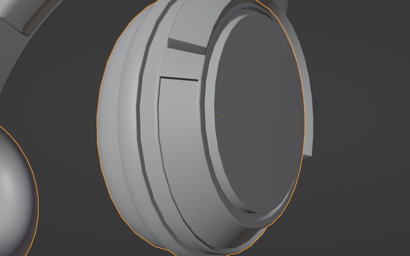
Figure 1.44 – Secondary detail added to the earcups
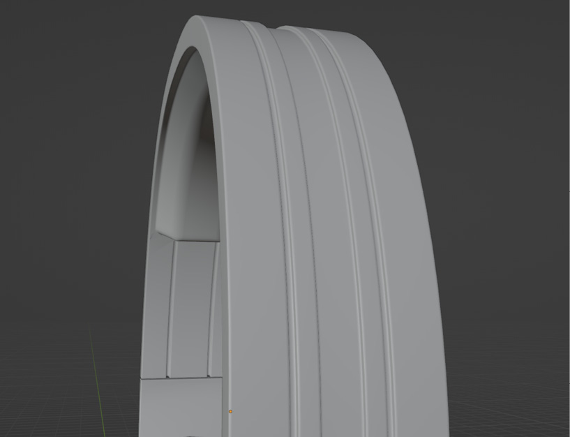
Figure 1.45 – Secondary detail added to the headband
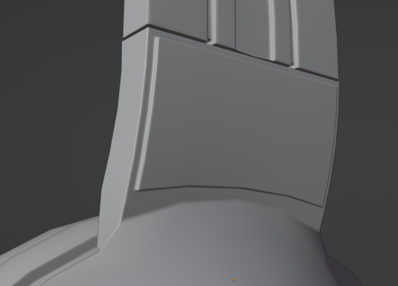
Figure 1.46 – Secondary detail added to the bottom part of the headband
As you can see, the secondary details added made our headphones look less “bland” and generic. Rounded edges were also added with a bevel modifier, but if you plan on doing the same, be very careful as it adds a significant amount of geometry, which can make the model too heavy for a game: what once was a headphone with only around 3.5k faces turned into nearly 11k faces just by adding the bevel modifier set to 3 faces.
It does look nicer though, so you need to find a balance between looks and the object’s importance in the game. For example, if the model is going to be seen from far away, you probably don’t need the rounded edges, but if it’s going to be very close to the player, you can use more detail if your object needs to look realistic. We’re going to keep the bevel modifier for looks but you might not want to add it (it won’t make a big difference to the process).
We should avoid applying the bevel modifier as much as possible for now, as applying it will make our life way harder when we move on to unwrapping the model (which will be explained later on).
Here are the full headphones with secondary details added:
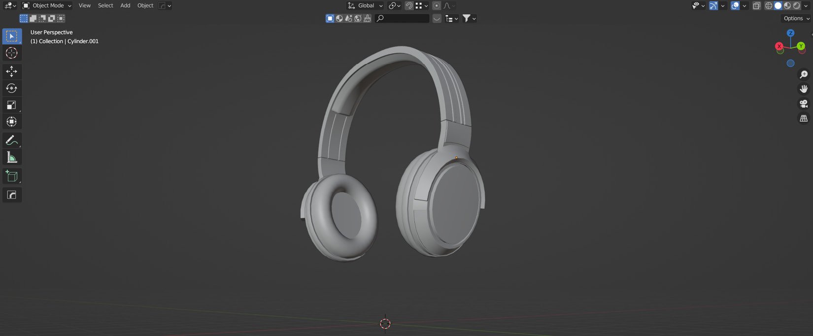
Figure 1.47 – Full headphones with secondary details
Tertiary details
This type of detail is composed of smaller shapes such as bolts, small wires, smaller indents, small holes… small shapes in general.
As with any type of detail, some sort of balance should also be struck with its usage throughout the model; note that not every part of the object will need this LOD.
As for our headphones, tertiary detail is more useful for the lower parts, so here is a suggestion for what could be added:
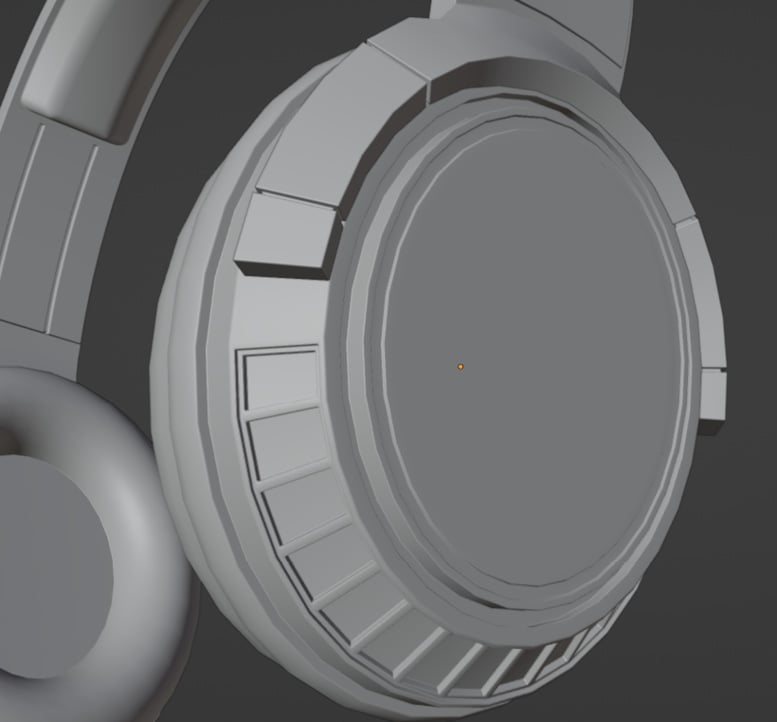
Figure 1.48 – Tertiary details added to the earcups and bottom part of the headband
This was done using the same techniques explained before, except for the grid-like structure on the earcups, which were done using individual face insetting, by pressing I twice when insetting more than one face. Then, we can extrude the faces along the normals as usual. After that, this is what the full model looks like:
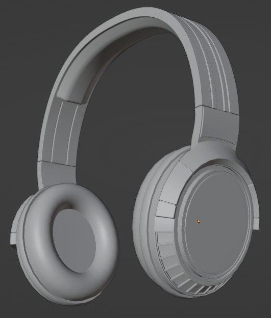
Figure 1.49 – Final model after adding tertiary details
Congratulations, you finished the modeling part of your asset! Now, we might need to optimize it to make it lighter to render.
As a quick reminder for future projects, here’s a small table with a few of the most useful and common modeling shortcuts learned by now:
|
Shortcut |
Function |
|
Tab |
Switches between viewport modes |
|
Shift + A |
Adds an object |
|
G |
Grabs the selected objects/faces/edges/vertices |
|
S |
Scales the selected objects/faces/edges/vertices |
|
R |
Rotates the selected objects/faces/edges/vertices |
|
I |
Insets the selected faces |
|
E |
Extrudes the selected faces/edges/vertices |
|
Shift + D |
Duplicates the selected objects/faces/edges/vertices |
|
Ctrl + B |
Bevels the selected edges |
|
Ctrl + A |
Applies a parameter, selected in the menu |
There are many more shortcuts, and some of them will be covered and used throughout the next chapters, but these are some of the most used ones.
Summary
In this chapter, we covered how to model an inorganic asset from scratch, as well as learning about most of the main inorganic modeling tools available by default in Blender and where to add the different LODs in an additive way. This is the first part of creating any 3D model and sets the LOD of the next steps, such as texturing.
In the next chapter, we will cover optimizing our model to make it lighter in terms of geometry so that we can render it more easily.