Download code from GitHub
Getting Started with Turning and Its Tools
Moving from 3D computer-aided design (CAD) models to manufactured parts may look like a giant leap difficult to overcome. In reality, it is not something to be scared of, and in the following pages of this book, we will try to explain step by step all the major challenges to overcome. In the end, you should have gained more confidence with machining and the manufacturing world in general.
In this chapter, we will approach a lathe for the first time, exploring components, terminology, and best practices without relying on prior knowledge.
The goal of this chapter is to let you familiarize yourself with the theory before approaching real case scenarios. Although you may want to start spinning your chuck immediately, a dive into basic concepts is very important; after all, behind every successfully machined part, however complex it may be, there is always the fundamental underlying theory.
We will also discuss turning, reaching a general understanding of what is possible and what is not possible with this method. This type of knowledge is fundamental to unleash turning's potential, instead of trying to copy and paste provided examples into your machining scenario.
In this chapter, we will cover the following topics:
- Approaching a lathe and its components
- Understanding the main parameters
- Exploring main machining strategies
- Understanding tool geometry
Approaching a lathe and its components
Turning, long story short, it is a very old machining technique discovered thousands of years ago. While understanding Egyptian pottery may sound interesting to some, it is definitely out of the scope of this book, so we are going to jump right into the action!
Turning is a mechanical process where a cylindrical part is put on fast rotation, and then approached by a cutting tool that progressively removes material from it. The machine that lets us shape our part with this technique is called a lathe.
If you ask a professional CNC user, they will tell you that a lathe is a rather complex machine that consists of many components such as the saddle, the tailstock, the headstock, and so on. Don’t worry about all these intimidating words—we will approach turning in the simplest way possible. In the following screenshot, we can find a lathe stripped up to the bones:
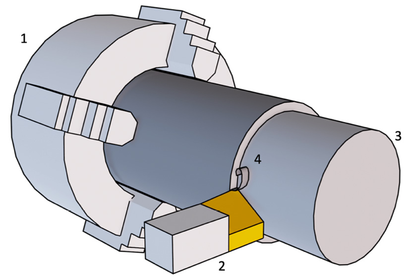
Figure 1.1: Lathe main actors
Ultimately, there are only four actors involved in turning:
- Chuck: A fast-spinning clamping device; it holds the stock to be machined
- Cutting tool: A special hard-metal blade that removes material from the stock
- Machined stock: Our part before machining is completed
- Chip: The removed particles and filament (waste material)
If you have ever approached a working lathe, I’m sure you noticed that the material shape about to be machined—the stock—spins very fast, while the cutting tool moves quite slowly, with a lot of chips being generated and projected all over the surrounding environment.
Even if the chip is valueless, it doesn’t mean that we can pretend it doesn’t exist; if we did, it would very easily render our part and our tool valueless. Controlling chip formation is very important (not only for turning) because it has the bad habit of becoming an entangled mess (a little bit like pasta) and damages everything it comes into contact with.
There are several types of lathes on the market; some are really big and some are very complex, but at the end of the day, all of them are pretty similar to one another.
Now that we understand the main components of the lathe, we can dive just a little bit into the theory behind such an incredible machine!
Cylindrical coordinate system
In order to understand coordinates, we need to remember that we live in a 3D world. In our world, in order to specify the location of an object with exact precision, we must provide a set of three numbers (coordinates) that measure the distance from a point in space—the origin—in a given direction.
In our daily lives, we often use Cartesian coordinates; here, we have a few examples:
- When working in an Excel file or when playing Battleship, in order to locate a cell, we need to know the row number and column number (2D Cartesian coordinates)
- If we want to give the dimensions of an object, we must provide the length, the width, and the height (3D Cartesian coordinates)
However, as mentioned, all the examples previously listed are Cartesian coordinates, where coordinates are expressed as a length along axes oriented at 90° from each other.
Orienting all the axes at 90° is generally the best approach for parts with a cubic shape, however, when it comes to lathes, a different coordinate system may be better. This is because all parts machined with a lathe have an axial symmetry, meaning that basically every part looks more or less like a cylinder. Therefore, we can use cylindrical coordinates instead.
With cylindrical coordinates, we do not express a point position with three distances; we express a position with an angle and two distances. We can see this in the following screenshot:
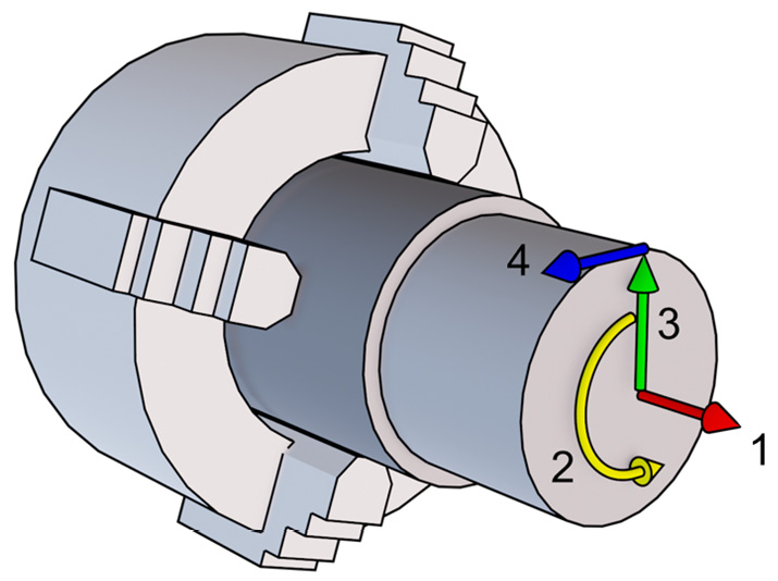
Figure 1.2: Cylindrical coordinates’ components
Let’s specify what the labels mean:
- The red arrow is the axial direction (longitudinal), which is the rotation axis.
- The yellow arrow is the rotation angle (
 ).
). - The green arrow is the radial direction. Note that the arrow is not static; you can pretend it is a hand of a clock, where all the ticks on the dial would be a possible radial direction. There are infinite green arrows around the rotation axis, each rotated by an angle (
 ) from 0° to 360°!
With these three numbers, we already can specify with extreme precision every single point inside and outside our stock. However, it will be useful to introduce another direction.
- The blue arrow is the tangential direction. It may not be so simple to understand the tangential direction, but we can just say that it is a vector that starts from the tip of a radial vector with a direction perpendicular both to the radial vector and to the axial vector.
Now that we know a bit more about cylindrical coordinates, we can start using this knowledge to differentiate between turning operations!
Different types of turning operations
To discuss the different types of turning operations, we will look at the two main families of machining:
- External machining
- Internal machining
Let’s take a look at these in more detail.
External machining
These operations are the most common operations performed while turning. In this type of process, the material is removed from “outside-in” along the radial direction. This basically means that the average radial coordinate of our tool will keep reducing during the operation.
In the following screenshot, we have a typical external machining operation depicted:
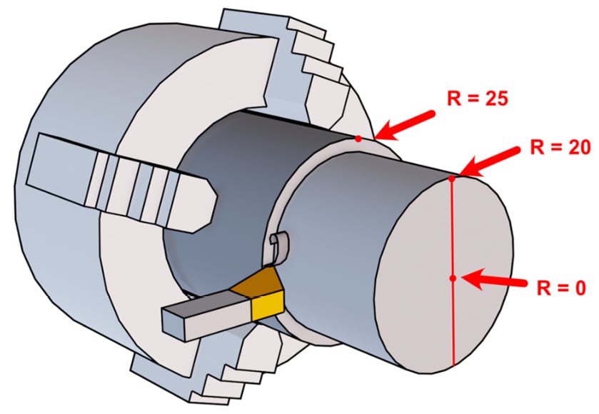
Figure 1.3: External machining example
Just by glancing at the figure, we should understand that the tool starts on the outside of our part where the radial coordinate is at the maximum, while machining it will progressively reduce it when moving toward the center (where the radial coordinate is 0).
Since, as we will discover, there are many different types of machining strategies, it is a bit difficult to find a strict definition for external machining; however, everything will be clearer when compared to the next machining approach.
Internal machining
These operations are different from the previous case since the material is removed “inside-out.” So, the average radial coordinate for our tool is growing during the operation:
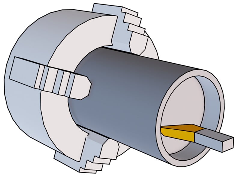
Figure 1.4: Internal machining example
As you can see from the previous screenshot, the tool is moving inside our stock, and the cut chip may find itself stuck in the cavity since there is material all around the tool. As you can also see, the tool is still quite visible, but there are cases where we may completely lose the line of sight after a certain depth, and this is not good for beginners.
As a matter of fact, when we first approach turning, it is always a good idea to look constantly at our part while being machined since we can check the surface finish, prevent unforeseen collisions with parts of the stock or parts of the lathe, and monitor chip evacuation. For all these reasons, internal machining may be a bit trickier than external machining.
Note
As a rule of thumb, if the forming chip is somehow free to flow and falls on the ground, we are in external machining; if it can be stuck inside, we are in internal machining.
It is now time to explore something a bit more technical but really important to understand: working parameters!
Understanding the main parameters
It is now time to talk about the parameters involved in our turning operations. First of all, what is a parameter? In short, a parameter is a value or a setting that we can change.
Of course, some parameters are easier to change than others. For example, changing the axial movement speed for our tool is very simple, while on the other hand, changing the maximum cutting power may require a bigger and more powerful lathe.
Also, as we will shortly discover, some values are somehow connected to others; changing one parameter may change one or more others, so we have to optimize parameters according to our lathe specs and to the part we want to machine.
Let’s find out what the main parameters are that we have to work with.
Turning speed
The turning speed is a measure of how fast the chuck is spinning; it may be measured in radians per time unit ( ) or in revolutions per time unit (
 ).
).
As shown in the screenshot, the bent vector represents the part spinning along the longitudinal axis:
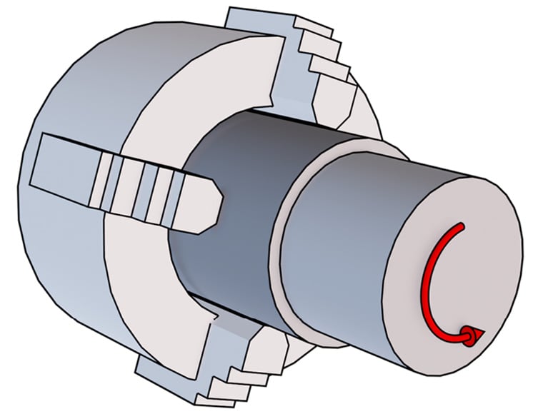
Figure 1.5: Turning-speed visualization
One revolution of our chuck corresponds to an angle ( ) of 360° or
  (depending on whether it’s measured in degrees or radians). But, since
  is measured in revolution per time unit, we need to divide the angle by the same time unit, so that from the angle, we get angular speed (
 ).
).
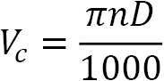
In short, we just need to remember this formula:

Old lathes had turning speeds that were only adjustable by manually changing the belt and pulleys, or changing the gears. Today, there are lathes that can control the rotation speed with inverters and encoders. So, depending on your lathe, the turning speed may or may not be a parameter that's easy to change.
Note
Please be careful when dealing with time units: sometimes the time unit may be seconds and sometimes minutes. As you can imagine, one revolution per minute is very different from one revolution per second, so when using any formula, please always be sure of its units!
Cutting speed
The cutting speed ( ) is the relative speed between our cutting tool and the surface it is cutting. There is only one important thing to notice, which is that the cutting speed is highly dependent on the radial position of our tool: the bigger the diameter means the higher the cutting speed (at a constant rotation speed).
As you can see in the screenshot, we have a common rotation speed for the two tools (since the chuck rotation is always the same); however, as you may have noticed from the different arrow lengths, the tool that is machining a bigger diameter has a much higher cutting speed (vertical vector) than the tool machining a smaller diameter:
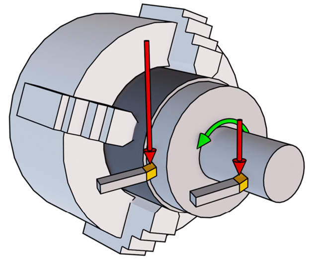
Figure 1.6: Cutting-speed visualization
Note
A vector can be defined by a magnitude and a direction. Magnitude is represented by the arrow length, while the direction is represented by the direction of the pointed tip.
Cutting speed is typically measured in meters per minute (m/min), and there is a very simple formula for calculating it:
Here,  is the diameter in millimeters (mm) and
  is revolutions per minute (RPM).
For example, let’s imagine we have a chuck rotating at 500 RPM, and we are performing a longitudinal operation at a constant radial distance of 50 mm (basically, we are machining a stock with a diameter of 100 mm). What is the cutting speed seen by our tool? It's very simple:
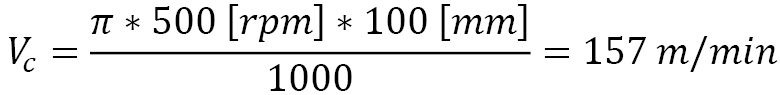
Now that we have seen the cutting-speed formula, it should be now clear that when machining a shape with different radial coordinates assumed by our tool, the cutting speed will be subject to changes. Since the working diameter is not a parameter we can change (it is related to the part shape we want to machine), in order to change the cutting speed, we can only adjust the chuck RPM. That’s why most of the time, you will see bigger parts spinning slower and smaller parts spinning faster! Once the tool is almost at the rotation axis, the cutting speed will always drop to zero, independently of how fast the chuck is rotating.
Cutting depth
The cutting depth ( ) is a parameter that gives us a measure of how much we impose an interpenetration between our tool and our part; it is measured in mm. Basically, it is related to how much of our cutting edge is engaged with the stock:
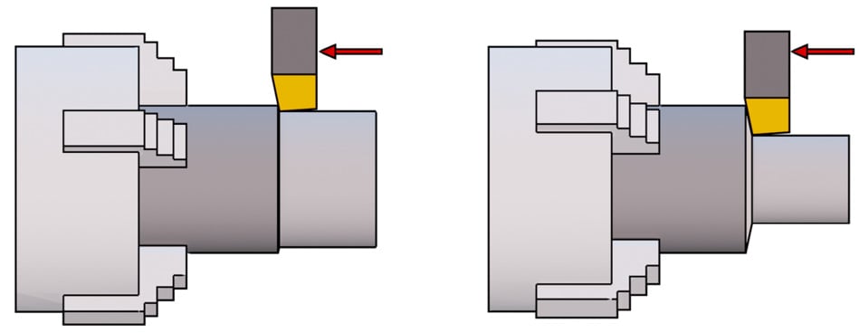
Figure 1.7: Cutting-depth visualization
As we can see, there are two tools machining the same diameter. The one on the left, however, is engaging the stock at a very small cutting depth, and therefore it removes only a thin layer of material. The tool on the right is cutting at a much bigger cutting depth and therefore it is removing a much thicker layer, and most of the cutting edge is engaged.
Please note that cutting depth is not always measured in the radial direction; sometimes, it can be measured in the axial direction. It mainly depends on the type of machining process we use (we will explain this in the Exploring main machining strategies section later in the chapter).
Higher cutting depth means more material removed and therefore faster machining, but requires more cutting power and leads to higher stress on our tool and our part. For this reason, please consider that higher cutting depths may partially bend our stock (especially if it is long and supported on one side only). Bending may lead to weird shapes with a rough finish.
Cutting feed
The cutting feed ( ) is a parameter that measures how much our tool is advancing along the cutting direction at every revolution of our chuck, and therefore it is measured in mm per revolution (mm/rev)
Similar to cutting depth, higher feeds lead to higher machining speed at the cost of higher tool wear and higher power being required. The part finish is highly connected with feed values; as a rule of thumb, a lower feed value means higher surface quality.
In the following screenshot, we have two tools machining the same stock at the same cutting depth:
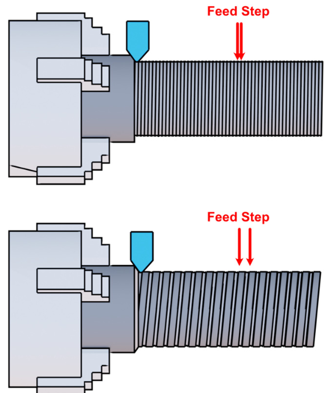
Figure 1.8: Feed visualization
However, in the first example, there is a much smaller feed step than in the second, so though they have the same turning speed, the tool on the bottom will reach the end of the stock much quicker, at the cost of higher surface roughness.
Be careful, as certain operations must be performed at a constant feed, such as threading. Threads have a constant pitch per rotation; therefore, we must set the feed to be equal to the thread pitch in such a scenario.
Note
Threading is the process of making a thread. It may be related to a male thread (such as a screw) or a female thread (such as a nut).
Adjusting the feed will also affect the chip. We can assume that a lower feed will produce a very long and entangled chip, while a higher feed will produce small particles. This is illustrated in the following screenshot:
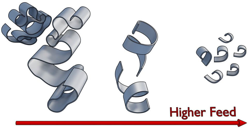
Figure 1.9: Chip formation related to feed
We should always try to hit a sweet spot in chip thickness, width, and length. The ideal chip shape is the one in the middle of the screenshot.
Note
Chip formation is a very interesting world of its own. I don’t really want to distract you from the main topic; however, if you want to learn more about chip formation and different chip types, I suggest you take a look at this interesting link: https://www.bdeinc.com/blog/types-of-chips-formed-during-cnc-milling/.
Cutting power
The cutting power is the mechanical power required to machine our part at a given set of parameters. It is measured in kilowatts (kW).
Before setting all our parameters, we must always check whether our lathe is powerful enough to handle the machining we want to perform. This is the simple formula to remember:
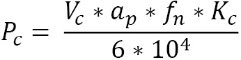
Here,  is the cutting power measured in kW;
  is the cutting speed measured in m/min;
  is the cutting depth measured in mm;
  is the feed step measured in mm/rev; and, finally,
  is the specific cutting force measured in MegaPascal (MPa).
As you may have noticed, there is a new value called  that we haven’t seen yet. is a parameter related to material strength, tool shape, feed ratio, and cutting depth. This is a difficult parameter to evaluate, and I don’t want to bother you with complex calculations… but luckily, I don’t have to. We can simply refer to tables where equations are already sorted out by experts. Please note that this is a rough approximation of the real value, so you may want to take it with a grain of salt and have a bit of a safety margin on cutting power!
Here, we can find an example of the most common iron alloys:
|
Material/Feed |
0.1 mm/rev |
0.2 mm/rev |
0.3 mm/rev |
0.4 mm/rev |
0.6 mm/rev |
|
Cast iron |
3200 MPa |
2800 MPa |
2600 MPa |
2500 MPa |
2300 MPa |
|
Mild steel |
3600 MPa |
3100 MPa |
2700 MPa |
2500 MPa |
2300 MPa |
|
Medium steel |
3100 MPa |
2700 MPa |
2600 MPa |
2500 MPa |
2300 MPa |
|
Hard steel |
4050 MPa |
3600 MPa |
3300 MPa |
3000 MPa |
2600 MPa |
|
Tool steel |
3200 MPa |
2900 MPa |
2600 MPa |
2500 MPa |
2400 MPa |
Figure 1.10: Kc approximation for steel and iron
Using such a table is quite simple: we simply select the row according to the material we are about to machine, then we select the column with a feed similar to the one we plan to use, and the result approximates the real  value.
Note
If you are intrigued by this parameter, you can find all the formulas for a precise evaluation of here: http://www.mitsubishicarbide.net/contents/mhg/enuk/html/product/technical_information/information/formula4.html.
As you can see, there is a very useful formula where we can insert our cutting parameters to get our  value. If you are hungry for more formulas, there is a very good explanation about
  here: https://www.machiningdoctor.com/glossary/specific-cutting-force-kc-kc1/#k1c-and-mc-chart-for-material-group.
With that last equation, it is now easy to understand that all parameters are connected and that we must change them accordingly to meet the maximum cutting power available for our lathe.
You may be wondering whether it is a must to target maximum power. No, it is not, but from the production point of view, not using our machine at its full potential will cost us more money per hour. However, a typical scenario where we will not use maximum cutting power is when we are machining a fragile material that we may damage with our chuck closed at maximum force to sustain chuck torque.
Now that we have covered the main parameters, we should better understand our lathe. Next, let’s jump into something juicier: turning operations and strategies!
Exploring main machining strategies
When we plan how to machine our part out of the stock, we have to think like a chess master. What I mean by this is that we have several pieces we can play with, but in order to win the game, we have to use every component in the best possible way it can be used. Therefore, we need to plan which piece to play first and with which type of move: do we move the bishop or the queen? Do we move by one square at a time or full speed ahead?
In the following sections, we are going to discover the main moves we can play with when it comes to turning.
Longitudinal operations
Longitudinal machining is a simple and common operation strategy, suitable for rough machining with high power and strong tools. Let’s check a basic example in the following screenshot:
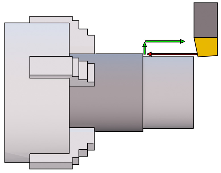
Figure 1.11: Longitudinal machining approach
The typical approach for longitudinal operations is to move the tool on the front of our stock (at a safe distance), set the cutting depth in the radial direction, and then move the tool forward. As we can see in the screenshot, while cutting, our tool is moving along the axial direction only, so we have a constant cutting speed per cutting pass. Once at the desired distance, the tool will disengage our stock radially and then repeat the process until the right diameter is machined.
Since this is longitudinal machining, the main cutting direction is on the longitudinal axis at a given radial distance; therefore, after a chuck rotation, our tool will be moved by one feed step along the longitudinal direction.
As a recap, in this type of machining, the cutting feed is along the axial direction, while the cutting depth is fixed and constant and is measured along the radial direction. As we are about to discover, there are other machining strategies where what we just said doesn’t apply.
Facing operations
Facing is used when we need to clean the front face of our stock:
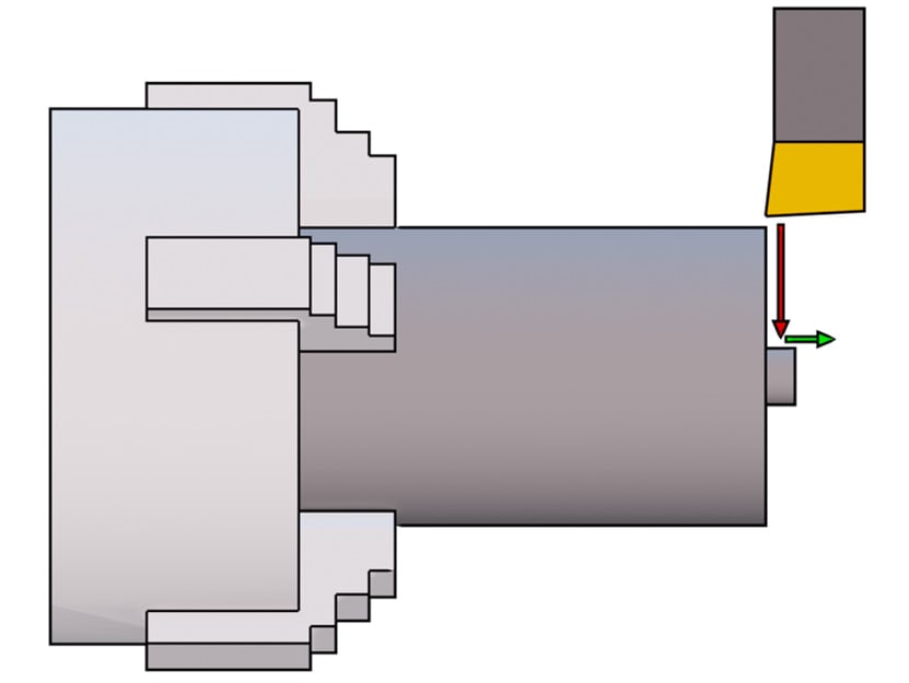
Figure 1.12: Facing machining approach
As shown here, while cutting, our tool is moving in the radial direction only; therefore, the cutting power will keep changing unless we adjust the feed or rotation speed accordingly.
The standard approach for facing operations is to move the tool at a safe distance in the radial direction, set the cutting depth in the axial direction, and then approach the stock radially. Once at the desired position, the tool will disengage our stock axially and then repeat the process until the right length is machined.
Since in facing, we are basically cleaning a slice of our stock, we are operating at a fixed axial coordinate and our tool is moving radially. So, after a chuck rotation, our tool will be moved forward by one feed step along the radial direction.
As a recap, when facing, the cutting feed is along the radial direction while the cutting depth is along the axial direction (this is different than longitudinal operations!).
Plunging operations
Plunging is similar to facing since the tool is moving in the radial direction only; however, because plunging is used for grooving or cutting, the tool is much slimmer. That’s because circlips grooves can be very thin, and our tool needs to fit inside them. Another reason is that when cutting our part, it is not a good idea to perform a large cut because that would require a lot of material removed without a real need.
As already mentioned for facing, since radial coordinates are always changing, so does the cutting power, unless controlled by feed changes or RPM.
As shown in the following screenshot, the typical approach for plunging is to position our tool at a safe radial position, set the desired axial coordinate, and then approach the part radially:
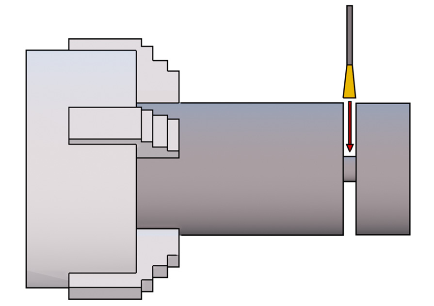
Figure 1.13: Plunging machining approach
So, to recap this strategy, plunging is similar to facing since it has feed along the radial direction too, but the main difference is that we cannot set the cutting depth since the tool cutting edge is always engaged entirely; therefore, the cutting depth is always at the maximum possible value!
Profiling operations
Profiling is one of the most complex operations since the tool moves constantly radially and axially. Let’s check the following screenshot for an idea of how profiling works:
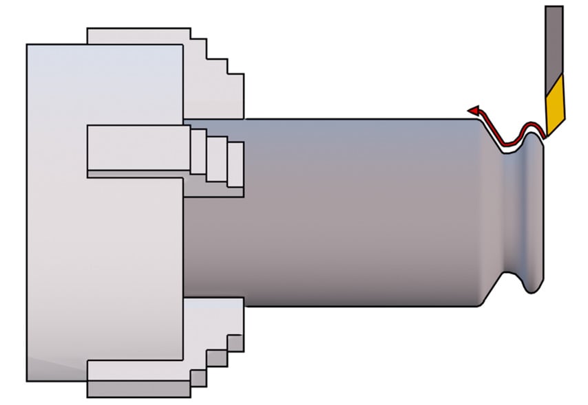
Figure 1.14: Profiling machining approach
As shown in the screenshot, the motion path of our tool can be very complex; therefore, this type of operation is the most flexible and is well suited for finishing our part. However, due to the fact that the cutting direction is not constant, there is always the risk of impact between the tool and our stock. As you may have noticed in the screenshot, after “climbing the first hill,” our tool will likely collide with the stock since the required path is too steep for the tool to pass.
To reduce the possibility of errors, an impact simulation is always a good idea in CAM, but for complex machining operations such as profiling, you must always check the results. Especially when a beginner is approaching turning for the first time, 99% of the time they will discover that the back of the tool or the shank will collide where the profile gets too steep or too narrow.
If we want to analyze what happens to our cutting parameters when profiling, we have to remember that the profile is not constant along the radial direction nor along the longitudinal direction; it keeps changing. So, unless our chuck is able to control rotation according to the tool’s radial position, the cutting speed will not be constant.
Having said that, we also need to remember that feed is measured along the cutting direction, so it will keep changing along the profile; the same can also be said for cutting depth.
Finally, we are at the end of yet another section. There is only one last major topic to cover: tool geometry.
Understanding tool geometry
As we discovered, there are many possible operations and geometries that we can machine on our lathe, but not every tool is suitable for every operation (always remember the chess analogy). We are now going to classify tool geometry in order to recognize, at first glance, which tool is more suitable for which machining strategy.
We can split the geometry of a cutting tool into three main categories:
- Tool edges
- Tool surfaces
- Tool angles
Let’s start with our deeper analysis of the geometry.
Tool edges
In the following screenshot, we can see a tool with a transparent shank where the edges are highlighted:
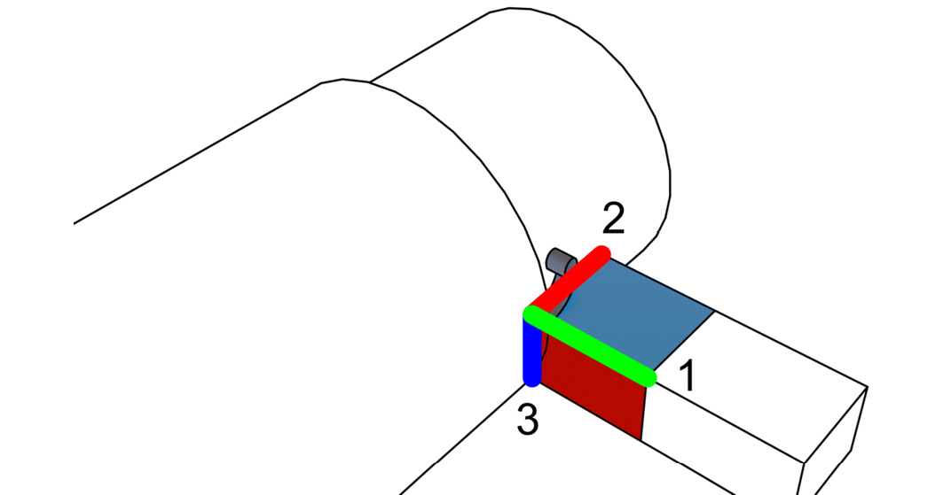
Figure 1.15: Main tool edges highlighted
You’ll notice that the tool shown is very crudely drawn and is simply a square. In reality, as we are going to discover, tool geometry is way more complex; however, at the moment, we will pretend it is a real tool since understanding surfaces and edges will be simpler this way.
- The main cutting edge
- The auxiliary cutting edge
- The nose edge
Cutting edge
As the name suggests, the cutting edge is a sharp edge that cuts our stock that is rotating against it. The cutting edge simply cuts along the feed direction and cuts the main portion of the chip.
Auxiliary cutting edge
In order to cut the stock, we need to cut in two directions. So, the auxiliary cutting edge cuts the side of the chip and removes the material from the stock.
Nose edge (radius)
The nose edge is not a real “edge.” It is never sharp because it wouldn’t last a single second while machining; instead, it is a “smooth edge” with a specific radius that can be bigger or smaller according to the tool we choose. A tool with a bigger nose radius will be less sharp and therefore will be able to sustain higher feed rates and higher cutting depths for a longer time.
Saying that, it is important to note that the nose radius is responsible for the surface’s finish. As you can see here, from a geometrical point of view, a higher nose radius will lead to less surface roughness when machining, and therefore to a better surface finish:
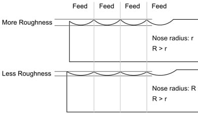
Figure 1.16: Changing the nose radius will change surface roughness
So, it looks like you may always want to use a large nose radius for roughing and for finishing… well, not so fast—there is a catch! When working at a low cutting depth (for example, when finishing a flexible part), a big nose radius will generate higher radial forces that are going to create strong vibrations (more details on that in the Entering angle (KAPR) section at the end of this chapter). Such vibrations will ruin the surface finish. A tool with a small nose radius will be super sharp and short-lasting, but also incredibly more effective at small cutting depths when finishing.
Now that we have learned something about the three main edges of every tool, let’s now start talking about the three main surfaces and their relative orientation.
Tool surfaces
All the edges listed up until now come into contact at the tip (or the nose) of the part. Three main surfaces are defined from this intersection. As always, it is way easier to understand the geometry by looking at a simple example:
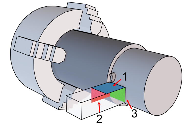
Figure 1.17: The main surfaces of a tool
Here, we can see three highlighted surfaces to study:
Let’s take a look at them.
Rake surface
The rake surface is the surface generated between the main cutting edge and the auxiliary cutting edge. It is the surface our chip is rubbing against before being evacuated. As you can imagine, much of the cutting power is transmitted to the stock through the cutting edge and the rake surface. At the moment, there is not much more to say about it, but as we will shortly discover, the main point of interest is its rotation.
Tool flanks
In our tool, we have two flanks:
- The main flank is generated between our cutting edge and our nose edge
- The auxiliary flank is generated between our auxiliary cutting edge and our nose edge
After that quick look at surfaces, let’s analyze angles.
Tool angles
When machining our part, we have many angles involved; some angles are related to the tool shape, while others are related to the way our tool is installed on the lathe.
Rake angle
The rake angle (  ) is the angle that describes how much our rake surface is rotated around the cutting edge. We can classify tools according to their rake angle, and we can distinguish three types of tool families: negative tools, neutral tools, and positive tools.
In the following screenshot, we can see those three tools, from left to right respectively:
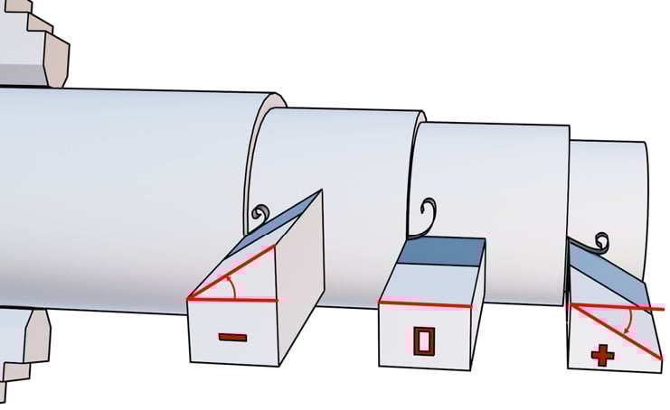
Figure 1.18: Rake angle visualized
More positive values will result in a super sharp tool (with a lower life span) capable of an easy-flowing chip very suitable for a surface finish.
More negative values will result in a stronger tool with a higher life span. Since the cutting edge is not so sharp, the tool will be great for roughing passes with higher cutting depth. As you can see in the screenshot, negative rake angles impose a hard twist in the forming chip; therefore, it won’t flow so easily and will break into smaller particles that may rub against the machined surface.
There is not much to say about neutral tools—their properties are a mix between positive tools and negative tools.
Please note that there is also a less important rake angle measured from the auxiliary cutting edge:
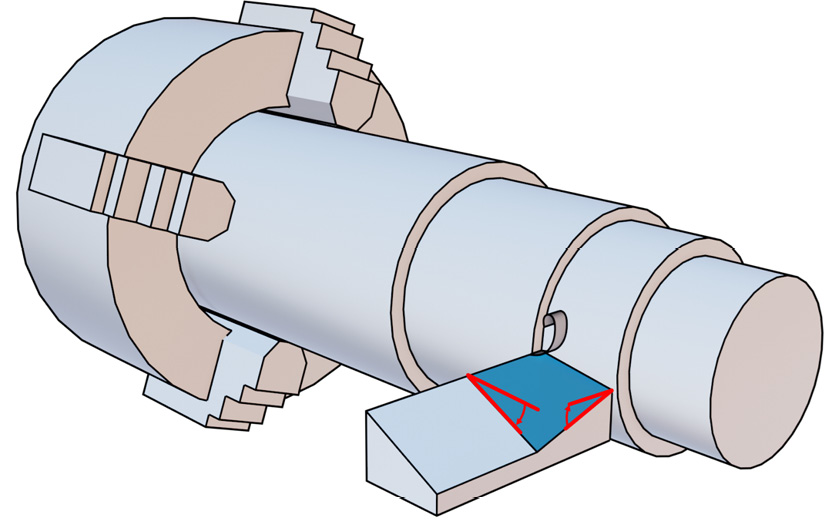
Figure 1.19: Rake angles
In the screenshot, we can find the main rake angle on the left and the auxiliary rake angle on the right.
Relief angle
When introducing tool flanks, we missed one important thing—they should never rub or collide against our stock or our machined part.
As you can imagine, the only part of our tool that should ever rub against our stock is our cutting edge(s). In the tools seen up until now, there is actually a really large surface rubbing against the machined part. Let’s analyze the following screenshot for a better understanding of what is going on:
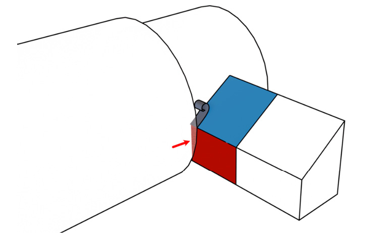
Figure 1.20: Friction area for a squared tool
As shown in the screenshot by the arrow, all that area is rubbing against the machined side! Not good at all! The same is true on the other flank.
To prevent this type of behavior, in real life, the two flanks are always rotated along the cutting edges by a relief angle in order to avoid friction. Every tool always has relief angles, and the angle value cannot be negative; otherwise, cutting edges would never engage the stock (because the bottom of the flank will hit the stock first):
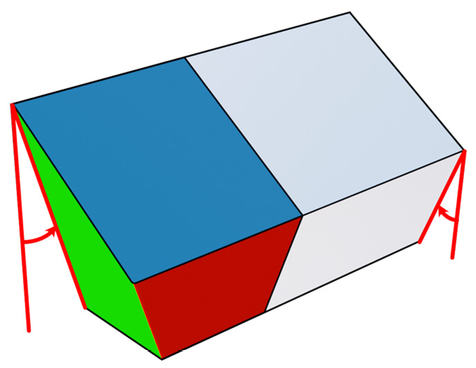
Figure 1.21: Relief angles displayed
We can find in the previous screenshot the auxiliary relief angle (on the left) and the main relief angle (on the right). These angles avoid friction with the turning stock while machining.
Nose angle
While looking at all the tools displayed up until now, you may have noticed that the angle between our cutting edge and our auxiliary cutting edge—called the nose angle—is constantly 90°. Just in case you are wondering… more often than not, this is not true; there are many different shapes available on the market!
Let’s check the following screenshot to grasp what the nose angle is:
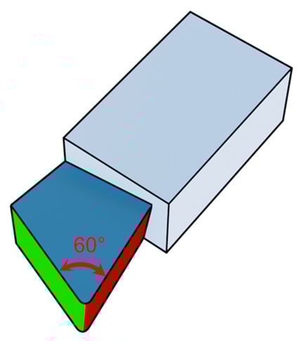
Figure 1.22: Nose angle visualized
Why don’t we try to analyze the tool shown in the screenshot? We should have lots of ways to analyze it. At the first glance, we should recognize that it is a positive tool (but almost neutral), that it has small relief angles on the two flanks, and as measured by the arrow, the nose angle is 60° with a small nose radius as well. Not bad!
This is a somewhat old type of tool; it has a large drawback: once the cutting edge or rake surface is really damaged, we have to throw it in the bin and buy a new tool. Today, the most typical approach is to have a tool composed of a shank and a swappable insert that can be replaced without changing the entire tool.
In the following screenshot, we can see on the left we have an “old-style” tool made in a single piece, while on the right side, we have a tool shank and a replaceable insert (both have the same cutting geometry):
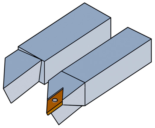
Figure 1.23: Insert versus solid tool
Also, please note that most of these inserts are symmetrical, so they have multiple cutting edges; once one of them is spent, we simply rotate the same insert and keep spinning the chuck!
In the following table, you will find a few typical insert examples with different nose angles and their suggested use:
|
TOOL SHAPE |
|||||||
|
Name |
R (Round) |
S (Square) |
C (Rhombic 80°) |
W (Trigon) |
T (Triangle) |
D (Rhombic 55°) |
V (Rhombic 35°) |
|
Preview |

|

|

|

|

|

|

|
|
Nose angle |
0/90° |
90° |
80° |
80° |
60° |
55° |
35° |
|
TOOL USAGE |
|||||||
|
Versatility |
0 |
0 |
+++ |
++ |
++ |
+++ |
+ |
|
High-depth roughing |
+++ |
+++ |
++ |
+ |
+ |
0 |
0 |
|
Low-depth roughing |
0 |
+ |
++ |
+++ |
++ |
+ |
0 |
|
Finishing |
0 |
0 |
+ |
++ |
+++ |
+++ |
+++ |
|
Profiling |
0 |
0 |
0 |
+ |
++ |
+++ |
+++ |
Figure 1.24: Tool specifications and typical use
The table shown is divided into two sections. The first part is related to the tool shape, where we can find the seven different families, their naming convention, and their shape. The second part of the table rates tool usage from “+++” to “0” (with “++” and “+” values in the middle). Let’s review the usages:
- Versatility: If we were alone on a desert island with our lathe, which tool would we take with us? A higher ranking (“+++”) means that that tool is a good choice in many situations and can more or less do everything. It is a workhorse and not choosy!
- High-depth roughing: If we need to remove a lot of material with rough passes at high cutting depth and high power, we need a very strong tool. A higher ranking (“+++”) means that the tool is tough and long-lasting, while a lower ranking (“0”) means that the tool is super sharp and will likely break or wear immediately.
- Low-depth roughing: In this scenario, we still need to perform roughing passes but with a thinner cutting depth. This case is somewhere between a roughing pass (where we remove a lot of material and we don’t mind about tolerances and surface quality) and a finishing pass (where we try to get good surface quality and tight tolerances). I decided to include it just to let you note that at low cutting depth, the round shape is very bad because it causes vibrations (this will be described later in the Entering angle (KAPR) section).
- Finishing: If we need to finish our part, we probably need to remove a thin layer of material. A higher ranking (“+++”) means a super sharp tool suitable for a good surface result.
- Profiling: With this ranking, we are going to evaluate which tool is better for machining complex profiles. A higher ranking means that the tool is very good and that it is not limited by accessibility issues, while a lower ranking means that the tool may often collide with the stock. The main difference between profiling and finishing is that the profiling score also considers shape accessibility.
We just mentioned shape accessibility—what does that mean? The answer is simple: slim and sharp tools can reach areas beefier and stronger tools cannot. Let’s check the following screenshot:
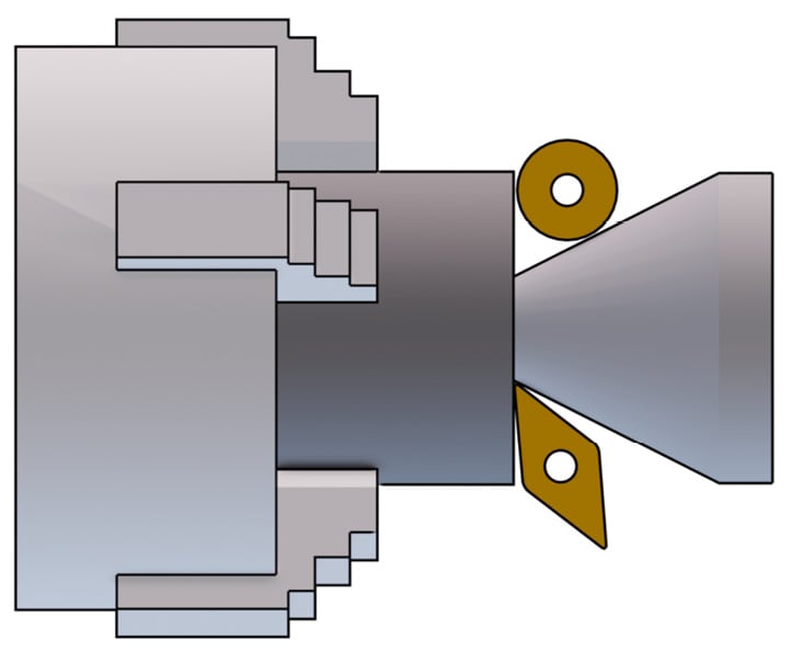
Figure 1.25: Different accessibility displayed
As we notice at the first glance, the round tool (type R) cannot remove as much material as a rhombic tool (type D) because the area to be machined is too deep to reach for it.
We have just taken a look at all the angles that we can find when looking at a tool on the workshop shelf. Is this the end? Not really—despite the tool shape, we can always decide to mount it rotated! Let me introduce you to the entering angle.
Entering angle (KAPR)
The entering angle is the angle measured from the feed direction to the cutting edge.
Changing the entering angle can dramatically change tool performance and chip management. In normal circumstances, it is always a good idea to set the KAPR close to 90°. With flexible parts, we should never set an entering angle lower than 70° if possible. The reason is pretty simple: changing the angle is actually changing the way our cutting edge is transferring power to the stock material:
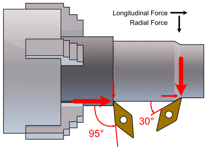
Figure 1.26: The same insert mounted at different KAPR angles
As shown on the left of the screenshot, when close to 90°, our tool is transferring power mainly in the longitudinal direction, and only a small percentage of the total is transferred as the radial component.
On the right, we can see that the tool is far from 90°, and therefore the radial component is much higher; this is bad, especially with flexible parts, because they will bend.
Why is bending a bad thing? Let’s review the following screenshot for a better understanding:
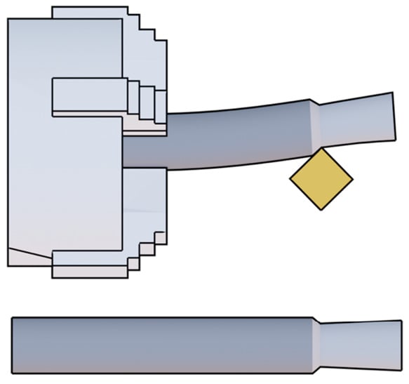
Figure 1.27: Bending
As you can see, the screenshot depicts a scenario where a slim part is machined with a longitudinal operation. Other than that, we can see that the tool has a 45° entering angle and a high cutting depth, which is the perfect recipe for high radial forces that will bend the part while machining.
As you can see at the top of the screenshot, the stock is heavily bent while machining, so we can imagine high vibrations due to the runout of the center rotation line and low surface quality.
As we can find at the bottom of the screenshot, after the machining is completed, what should have resulted in a nice cylindrical surface appears more like a cone with a higher diameter where the bending was more severe!
It may look like a small entering angle is forbidden, but not so fast. There are many different scenarios where we may have to use small angles; here are some examples:
- When we want to improve tool life span: At the same cutting depth, with a smaller entering angle, a bigger part of our cutting edge is engaged, and therefore the cutting force will be distributed over a bigger area with smaller stress on the insert that will last longer.
- When we want to machine a thread: Let’s take a look at the following screenshot for a better understanding of this example:
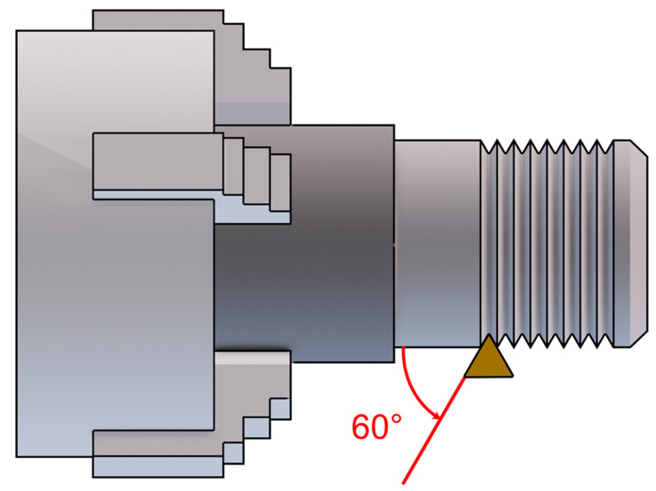
Figure 1.28: Threading operation displayed
As shown in the previous screenshot, when threading we must use an entering angle and a nose angle strictly dictated from the thread specs: 60° as KAPR and 60° as the nose angle (for most metric threads); that’s why the triangle insert is very often used for threading.
As we already mentioned, remember that when threading, many parameters are locked to thread specs: from the thread pitch, we must impose a certain feed step, and from the thread angle, we must use a tool with a specific nose angle, entering angle, and maximum nose radius. Do not underestimate the nose radius when threading: if it’s too large (over thread specs), the nut will not be able to be screwed on.
So, when threading, if we need to reduce vibrations or bending, there is only one parameter left… we can change the cutting depth only.
As a bonus point, let’s explain why the round tool shape can be a good choice at high cutting depth but may generate high vibrations at low cutting depth. Let’s analyze the following screenshot:
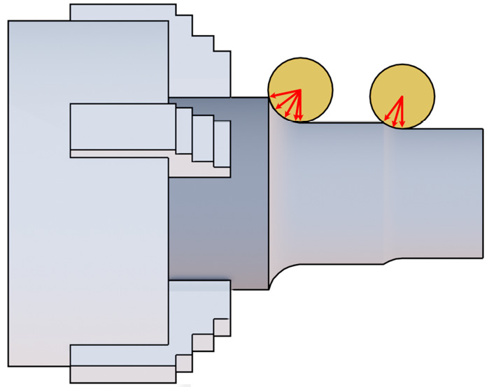
Figure 1.29: Round-tool KAPR
As you can see, the tool on the left is cutting at a high cutting depth; therefore, it is exchanging all the cutting force on a wide range of angles, from almost 90° to 0°, so the radial force generated is not a main issue. On the other hand, the tool on the right is engaging a thin layer only, and the cutting force is shared from almost 0° to 0°. Such a small KAPR will create massive vibrations—that’s why round tools are good for high-depth machining but not so much for low depths (and the same can be said for the nose radius).
When facing, a round tool may become handy even at low cutting depth since we don’t care that much if the force is transferred to the chuck!
There are many more formulas related to the entering angle, but they are probably way beyond the scope of this book, so we won’t deal with them. A last tip on the subject, though: just note that the entering angle is also responsible for the chip shape, so remember that the smaller the entering angle, the thinner and the wider the chip (and vice versa).
As shown in this last section, we should always pay close attention to the shape of the tools since they may look similar, but in reality, they are very different and may be the cause (or the solution) of many machining-related problems.
Summary
Congratulations! That was the end of the first chapter—I hope that the journey up until now was easy and pleasant.
Let’s quickly recap what we learned during this chapter. Firstly, we saw what turning is and how it shapes our parts, and discovered what the main components of a lathe are. After this, we moved to something a bit more technical: studying the cutting parameters and how we can control them and evaluate the cutting power required. Then, we moved forward to the main machining strategies used when turning and saw the main geometries of our tools and how they can affect machining.
All these elements are key for better awareness while planning a machining strategy. I encourage you to experiment and widen your knowledge by studying the specs of the tools you use on the manufacturer’s datasheet.
Please note that this chapter was an introduction to turning. We should now understand a bit better what we are talking about, but we definitely cannot consider ourselves turning experts. We had to simplify many concepts, and we made a brutal approximation; however, for most typical beginners, the provided knowledge level should be spot on.
Now, follow me to the next chapter where we are going to experiment with something more practical: using the Fusion 360 CAM module for our first turning machining setup.