


 Download code from GitHub
Chapter 2: Building an Industrial Robot Claw
Industrial robots have been around for a long time. In many cases, industrial robots are not the humanoid-looking robots we imagine when thinking of robots. Instead, many are robot claws that can do a wide variety of tasks, such as surgery, welding, assembly, painting, and more. In this chapter, you are going to build a robotic claw to pick up an object to better understand how these claws work and operate. In the following image, you can see what you will be building:

Figure 2.1 – A robotic claw
In this chapter, we will break down the build and program, as follows:
- Building the base
- Building the Intelligent Hub frame to move multidirectionally
- Building the robot arm
- Building the cargo
- Writing the code
- Making it your own
Technical requirements
For the building of the robot, all you will need is the SPIKE Prime kit. For programming, you will need the LEGO SPIKE application/software.
Access to the code can be found here: https://github.com/PacktPublishing/Design-Innovative-Robots-with-LEGO-SPIKE-Prime/blob/main/Chapter%202%20-%20Robot%20Arm%20Code%20.llsp.
You can find the code in action video for this chapter here: https://bit.ly/3xkt1Mj
Building the base
Before we build this claw, let's explore the strategy being used for this claw. There are many LEGO robotic claws to be found online. This claw will use the following tactics and strategies:
- The claw needs to be able to be controlled by a human.
- The claw needs to be able to move from side to side.
- The claw needs to be able to move up and down.
- The claw needs to be able to open and close to grab various objects.
We are going to start this build using a large yellow 11x19 base plate as the main building foundation for this robotic claw. Let's take the following steps:
- Ensuring that we have a solid foundation is key, and the yellow 11x19 base plate shown in the following image is perfect for building on top of when designing a claw:

Figure 2.2 – The LEGO yellow base plate
- We are going to need to add the second yellow 11x19 base plate:

Figure 2.3 – The second LEGO yellow base plate
- On each corner of the yellow base plates, you will add a gray perpendicular connector piece, as shown in the following figure:

Figure 2.4 – Add gray connectors to edges
- Next up, you will now add six 3L black axle pins with friction ridges to the sides, as follows:

Figure 2.5 – Three axles added to each side
- Now that we have plenty of connectors in place, it is time to build out the next part of the base, which will provide spaces for you to move an object from one location to another. Start by adding a yellow 3L beam and purple 11L beam to each side, as shown in Figure 2.6:

Figure 2.6 – Fill the space between the gray perpendicular connectors
- From this step, attach an azure 11x15 open center frame on each side. Hold this piece in place using an azure 7L beam and one gray perpendicular connector on each side.

Figure 2.7 – Attach the open frames for object delivery
- The final part to assemble on the base is the beginning space for your object. Begin by first adding two gray perpendicular connector pins to the front of the yellow base plate. Attach a black 3x11 panel plate to each connector. Next, attach the 8 black connector pins along this whole edge, as shown in Figure 2.8:

Figure 2.8 – Adding the black 3x11 panels
- The next set of elements will help hold everything together. Attach an azure 13L beam across the two black 3x11 panels using the black connector pins already in place. Insert three black connector pins to this beam, as shown in Figure 2.9.
Follow the same process for the two black 15L beams across the azure open frames.

Figure 2.9 – Building the support for the front of the base
- The final step to this section requires you to add two yellow 3L beams to either end of the azure 11L beam. Lock the black 5x7 open center frame to the azure beam using the black connector pin still available and using two more gray perpendicular connectors, as shown here:

Figure 2.10 – The final look of the base
You now have completed the base for the robot arm and the playing field to move an object from one open frame to the other. Our next step is to build the frame for Intelligent Hub to serve as our arm controller.
Building the Intelligent Hub frame to move multidirectionally
One part of this kit that is different from previous LEGO MINDSTORMS kits is that the wires for all sensors and motors are set to a specific length. In previous kits, we could attach various cable sizes as we built our bigger structures.
Because all wires are a set length that we cannot adjust, we must consider this creative constraint in the build design. With that being said, we need to build a frame to place Intelligent Hub at a certain height to allow the motors to be able to reach it while in motion.
In this case, you will build a base that will provide adequate height along with an opportunity for Intelligent Hub to spin and pivot up and down. Let's look at the following steps:
- To begin this aspect of the build, begin by securing two black biscuit elements to the yellow base plate using the blue connector pins. These are centered towards the back of the build and will be three pin holes from the edge. The following figure illustrates this:

Figure 2.11 – Biscuit elements added to the yellow base plate
- Next, attach the yellow 7L axle to the middle of the two black biscuit elements. Slide the tire through the yellow axle. On top of the tire, insert two blue connector pins in the top and bottom pin holes and secure another purple biscuit, leaving space on top to connect more elements, as shown in Figure 2.12:

Figure 2.12 – Biscuit element on top of the tire
- Once you have ensured everything is secure and connected, add one more tire to the top of the purple biscuit element, as shown in Figure 2.13:

Figure 2.13 – Second tire added to the top
- Just like the previous step, you will add another purple biscuit element to the top tire using two blue connectors pins but using the left-side and right-side pin holes, as shown in Figure 2.14:

Figure 2.14 – Securing another biscuit element
This next sub-model will sit on top of the two tires we just installed. This will serve as the housing unit for Intelligent Hub, allowing it to move forward and backward while using the tire build and spin right and left:
- To begin, locate a purple 7x11 open center frame and install four blue connector pins, as shown in Figure 2.15:

Figure 2.15 – Add four blue connector pins to the purple 7x11 open frame
- Attach another purple 7x11 open frame using the blue connector pins, as shown in Figure 2.16:

Figure 2.16 – Stack another purple 7x11 open frame
Keep in mind that, for this next part, I suggest you build the black open frame piece first. As you look at Figure 2.17, you can see how it fits within the purple 7x11 open frame, but it is not locked in at this point.
- For this step, there is a three-image process to help you see where all the pieces go in Figure 2.17:
- Attach a yellow 3L beam to both sides of the purple biscuit. Connect the yellow 3L beams using two black connector pins on the outside pins.
- Insert this build into the black 5x7 open frame.
- Take this piece and add a gray pin with a bush stop to the middle pin hole on both 5L sides of the black 5x7 open frame. This will allow these pieces to pivot back and forth.

Figure 2.17 – Piecing the elements together
And here is how it fits into the purple 7x11 open frame:

Figure 2.18 – Pivot piece for Intelligent Hub
- This piece will fit into the purple open frame but, as you can see, when building, it does not stay together, but for a point of reference, these will sit atop the wheels, as shown in Figure 2.19:

Figure 2.19 – Location of the piece on tires
- Lock this piece into the purple open frame by using four more gray bush stop pins and connect two on each side, as shown in Figure 2.20:

Figure 2.20 – Pins with bush stops hold it all together
- Add a tan pin connector to each of the gray connectors on the bush stop axle insert, as shown in Figure 2.21:

Figure 2.21 – Add tan connector pins to each bush stop
- We will now add the azure curved plates to each side to act as a joystick mechanism to help steer Intelligent Hub back and forth, as illustrated in Figure 2.22:

Figure 2.22 – Azure curved plates for steering
- Finally, the last step for the controller of our robot arm is to add the most important piece, the Intelligent Hub, as shown in Figure 2.23. The Intelligent Hub connects to the four blue connector pins in place in the purple open frame. Click all into place and spin your Intelligent Hub around to ensure it properly spins on the yellow axle. Additionally, it should also be able to lean forward and backward.

Figure 2.23 – Placement of Intelligent Hub
When you have tested these two movements, it is time to build the robot arm itself.
Building the robot arm
You are now ready to build the robot arm that will be controlled by Intelligent Hub. In order to achieve this, you will need to take the following steps:
- Start with four black connector pins and add them to the front yellow base plate, as shown in Figure 2.24:

Figure 2.24 – Placement of the black connector pins
- On top of these four black connector pins, add the large motor from the kit, as shown in Figure 2.25:

Figure 2.25 – Attach the large motor to the black connector pins
- Once your motor is secure to the yellow base plate, add two blue connector pins and one black biscuit to the motor. The blue connector pins will be placed on the top and bottom pin holes of the motor, not the right and left sides.

Figure 2.26 – Attach the blue connector pins and biscuit
Be sure your motor is aligned to position 0 (gray dots aligning):

Figure 2.27 – Motor aligned to position 0
- On top of the black biscuit element using the blue connector pins, you will add a medium motor facing to the left. Again, align the motor to position 0 (dots lined up as shown in Figure 2.27):

Figure 2.28 – Attach the medium motor
- This next part of the build is to create a simple stopper, so the robot arm does not go straight back and hit Intelligent Hub.
Begin by adding four black connector pins to the pin holes on the medium motor in the white pin holes. Attach two azure 7L beams facing up, as shown in Figure 2.29:

Figure 2.29 – Attach the azure 7L beams
- Add a yellow 2x4 L beam to the top of each azure 7L beam using two black connector pins for each one, as shown in Figure 2.30:

Figure 2.30 – Attach the yellow 2x4 L beams
This has been designed to be simple so that as you tweak this build on your own, you can easily remove these pieces if you wish.
It is now time to add the second motor for the robot arm by taking the following steps:
- Begin by adding two tan connector axle pins to the middle pin hole of the medium motor on either side. On the side of the motor with the azure motor element, add one black connector pin to the top pin hole, as shown in Figure 2.31:

Figure 2.31 – Prep for the claw
- We are now going to build a sub-model of the robot claw that will fit onto the connector pins we just added to the medium motor.
Start with one black 15L beam, as shown in Figure 2.32:

Figure 2.32 – Beginning of the claw build
- Using two blue connector pins, attach a black 9L beam to the 15L beam, as shown in Figure 2.33:

Figure 2.33 – Attach the 9L beam
- Using the two blue connector pins, add the second medium motor, as shown in Figure 2.34:

Figure 2.34 – Attach the second medium motor
- On the other side of the medium motor, which does not have anything added yet, use two black connector pins and attach another black 15L beam. Let's see what this looks like in an illustration:

Figure 2.35 – Attach another black 15L beam
- On the backside of the motor, insert a yellow 3L axle and two black connector pins to the right and left sides, as shown in Figure 2.36:

Figure 2.36 – Attach a yellow axle and pins
- Slide a purple 5L beam across the pin connectors. Add two more black connector pins to each end of the beam, as shown in Figure 2.37:

Figure 2.37 – Attach a purple 5L beam
- This next little build is what will allow your claw to open and close. Add a tan axle connector pin to a white axle and insert a pin connector element into the right axle hole:

Figure 2.38 – Claw movement mechanism
- Add an Azure 1x2 axle hole element to the pin side of the tan axle connector, as shown in Figure 2.39:

Figure 2.39 – Add the 1x2 axle hole
- Attach this build element to the backside of the motor, as shown in Figure 2.40:

Figure 2.40 – Insert into the medium motor
- Using the two black connector pins that are still open on the purple beam, add one yellow bent lift arm to each pin, as shown in Figure 2.41:

Figure 2.41 – Add the yellow lift arms to the motor
- If looking at the build straight on, you will add one black axle connector pin on the right side in the third pin hole from the bottom. This will connect the yellow lift arm to the white connector piece behind it. You will add one tan axle pin connector to the left yellow lift arm in the bottom hole. Let's see what this looks like in Figure 2.42:

Figure 2.42 – Add tan and black connector pins
- Secure the yellow lift arms together for movement to occur by using one H-shaped lift arm to hold them in place:

Figure 2.43 – Add a H-shaped lift arm
- The final step is to add some grippers so that the arms can hold an object without slipping. Add a yellow 3L axle through the end of each yellow bent lift arm, as shown in Figure 2.44:

Figure 2.44 – Add a yellow 3L axle beam
- Add a rubber gripper to each side, as shown in Figure 2.45. You will use four of them in total:

Figure 2.45 – Add grippers
- The final step is to now add this claw to the overall build design. Use the pins on the first medium motor to connect everything into place. Let's look at an illustration of this:

Figure 2.46 – Add the claw to the robot
- And you now have one sweet-looking robot arm build, ready to be programmed and brought to life! Let's have a look at it in Figure 2.47:
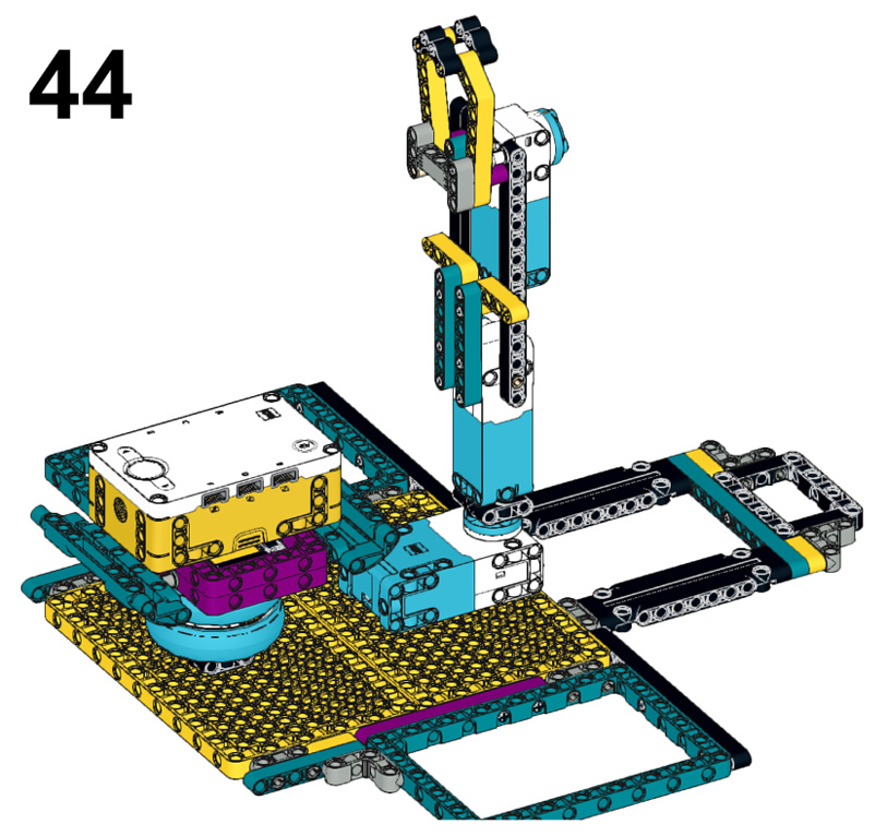
Figure 2.47 – Final view of the robot
Now that your claw is complete, we have one more item to build, which is an element to be picked up, so let's build a small cargo element.
Building the cargo
Now that the arm mechanism has been built, you need an element to pick up. You will now build a cargo build to practice using your claw:
- Start with two black 2x8 plates and place them side by side, as illustrated in Figure 2.48:

Figure 2.48 – Two black 2x8 bricks
- Connect these elements together using two purple 2x5 blocks and place them at each end, as shown in Figure 2.49:

Figure 2.49 – Join together using 2x4 blocks
- Insert a yellow 3L axle into the middle of each purple 2x4 block, as shown in Figure 2.50:

Figure 2.50 – Insert a yellow 3L axle
- Slide a gray bushing onto each yellow axle, as shown in Figure 2.51:

Figure 2.51 – Insert a gray bushing into each axle
- The next step is to add a yellow 90-degree connector to the top of each yellow axle, as shown in Figure 2.52:

Figure 2.52 – Add a yellow 90-degree connector
- The final step is to use a 5L axle and, in the middle, slide it onto a tire. Secure the tire using a gray bushing on each side. Finally, work the 5L axle into the two yellow 90-degree connectors, as shown in Figure 2.53:

Figure 2.53 – Add the tire to the middle of a 5L axle
This will be the cargo item we will use to grab and move to different locations. Next, it will be time to move on to the coding to bring the robot claw into use.
Writing the code
For this build, we are going to focus on writing code that allows us to use the Intelligent Hub as a remote control for the arm. This will be a program that allows you to control the robot using the gyro sensor feature of the Intelligent Hub to move the claw left, right, up, and down, and to open and close the claw.
Overall, this program is simple to develop and is created to be easily adaptable for you to remix to meet your needs. Use this sample code to make sure everything works, and then begin to tweak the code to make it work to your desired needs. Make sure you have the proper ports plugged in, and then move on to the code.
Identifying the ports
If you have not plugged in your motors yet, then let's get them plugged into the proper ports. You will plug the large motor that moves the claw to the right and left to motor port E. The medium motor that controls the opening and closing of the claw will plug into port A. The medium motor that controls the arm of the claw to go up and down will use port C. Once you have the motors plugged in, then double-check that the motors are plugged in correctly.
You can check that your motors are properly plugged in by checking the Hub Connection in the software, as seen in the following screenshot:
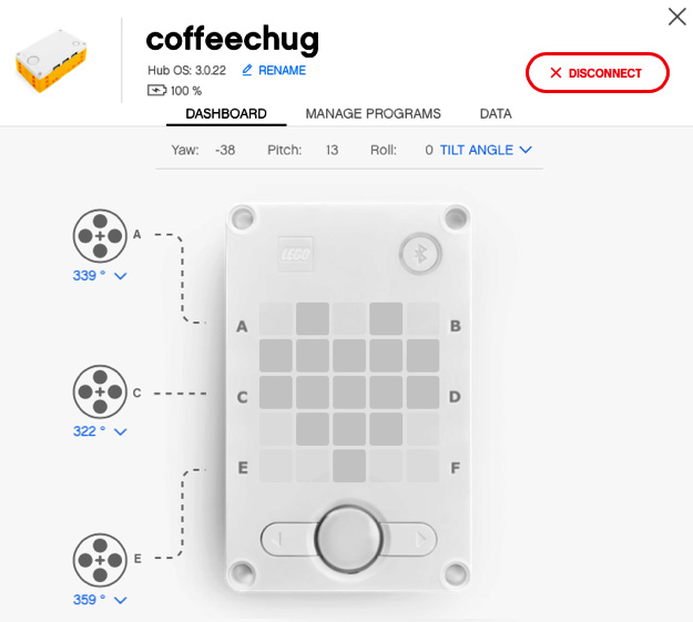
Figure 2.54 – Hub Connection view
It is time to write the program so that you can control the claw.
The Intelligent Hub remote-control robot program
To get started with this program, let's go ahead with the following steps to make the robot come to life:
- Open up the SPIKE Prime software.
Click on New Project at the center of the main screen:

Figure 2.55 – Choosing a new project
- On the New Project window, select the Word Blocks option, give your program name, and click on Create.
- When the coding canvas opens, there is already a default when program starts block provided, as shown in Figure 2.56. Let's begin with this code stack. We will add some code to align all our motors to a common starting point at the beginning of the code. Add a cyan sensor block called set yaw angle to under the when program starts block:

Figure 2.56 – Creating the initial code stack
- Yaw is the orientation of Intelligent Hub turning right or left, as shown in Figure 2.57. In other words, it is the rotation around the z axis:

Figure 2.57 – Yaw is turning Intelligent Hub left and/or right on the z axis
- The last two blocks we will add to this stack are blue motor blocks. Add two of the motor go shortest path to position blocks, as shown in Figure 2.58. Set one block for motor E and the other for motor C:

Figure 2.58 – Set motors E and C to the start position
We are now going to create a new code stack for the claw to close. Go to the Events code block section and select the block when left Button pressed. Change this block to right Button pressed. Add a blue motor block named run for 1 clockwise rotations. Change the settings of the block to motor A and change the settings to 7 degrees:

Figure 2.59 – Set the claw to close
You will now copy this stack and do the opposite to open. Right-click the Event block and you will see an option to Duplicate. Change this stack to left Button on the orange event block. For the blue motor block, change the direction of the turn to counterclockwise:

Figure 2.60 – Set the claw to open
- The final code stack will be created to allow the arm to move in the direction of Intelligent Hub using angle and yaw. Begin by adding an Event block named when program starts.
- Add a blue motor block to adjust the motor C speed to 5%. You can adjust the speed to your liking once you get the arm moving.
- The next block we will add is a Control block named
forever. In this block, add another blue motor block, moving motor E to the shortest path to position the block. Where the number0sits, you will add a cyan sensor block namedPitch Angle. Add that to0and then change the pitch to Yaw. Figure 2.61 will showcase what you should have at this point:
Figure 2.61 – Controlling arm code
- Next, we will create an
If Thenstatement and basically duplicate it two more times to complete the code. This will program the arm to follow the motion of Intelligent Hub. Go to the Control blocks and add an If Then block into theForeverblock of our code. Add a green Operator block ofless than. On the left side, add a cyan Sensor block of Pitch Angle, and to the right of the equation, add-3. Under that block, add a blue motor block, Start Motor, and change to motor C and in a counterclockwise direction:
Figure 2.62 – Arm move to the left
- We will now copy this format, but use different Operator blocks for
greater thanand another Operator block when the pitch is between-3and3. See Figure 2.63 for the rest of the code to complete the sequence:
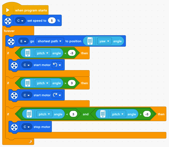
Figure 2.63 – Complete code for arm control
When it is all complete, your code should look like this:
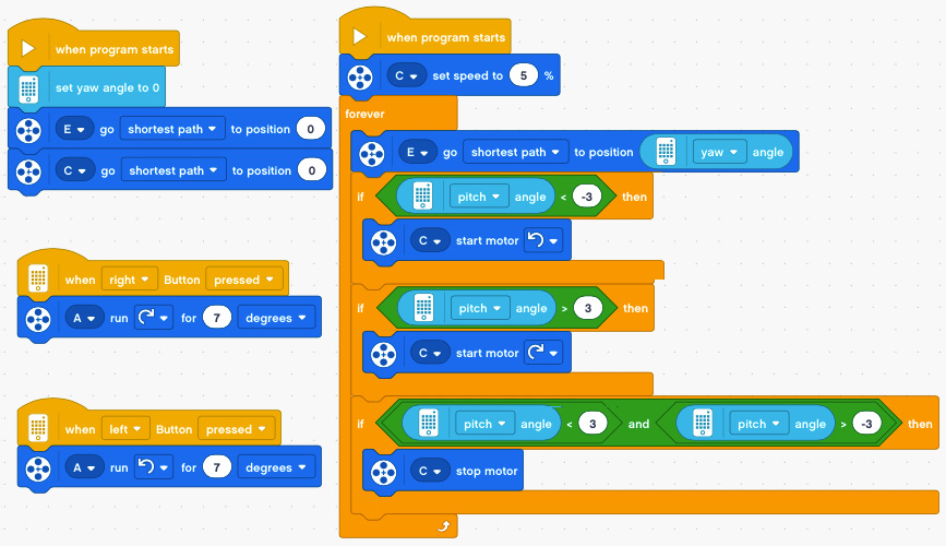
Figure 2.64 – Complete code for this project
And that is it! You did it. You built a nice-looking and working robot claw. Now comes the fun part, which is to remix the claw to make it your own. Let's look at some ideas.
Making it your own
This is the part I love, and I hope you do too. This robot is just the beginning of the fun. It is now time for you to take this framework of the robot build and sample code and make it unique to your talents and imagination.
Here are a few ideas to consider applying to this robot:
- Add sensors to trigger autonomous robot decisions. For example, could you add a color sensor so that, as the claw moves, it is waiting to detect a color to stop and pick up the object and move to another location?
- Could you program the arm to move without human interaction?
- Instead of using the buttons on Intelligent Hub to open and close the claw, could you use the Force Sensor instead?
- How could you modify the claw to grab different objects and sizes?
- Add lights from the Light-Emitting Diode (LED) matrix on Intelligent Hub to provide insights or cool new looks as the robot operates.
- Add sound effects to make it sound like an industrial robot.
Summary
Industry continues to rely on robotics to achieve production goals. By the end of this chapter, we had explored the concept of industrial robots by building a robotic claw that can pick up an object and transport it to another location. Additionally, we explored how to have several motors working together to create an actual working claw. This is a classic build that must be done with any new robotic kit!
Let's now head to the next chapter and explore a whole different world of robotics by building a guitar.

