


 Download code from GitHub
Chapter 1: Getting Started with the Raspberry Pi Pico
In this chapter, we would like to delve into a quick introduction to the Raspberry Pi Pico and the RP2040 microcontroller. We will discuss the Raspberry Pi Pico's features, the RP2040's peripherals, the add-on hardware for the Pico, and development boards for the RP2040 developed by other makers. We will also discuss the programming language options available for the Pico and supplement the chapter by discussing a simple "Hello World" example where we print something to the screen and blink a light-emitting diode (LED).
By the end of this first chapter, you will have gotten started with the Pico and will be ready to start programming the RP2040 microcontroller and start planning to implement projects from the later chapters of this book, as well as thinking ahead to how you can tackle your own projects with the Raspberry Pi Pico!
We are going to cover the following main topics:
- Introducing the Raspberry Pi Pico and RP2040
- Discussing variants of the Pico board
- Soldering the Pico's headers
- Implementing the "Hello World!" example
- Implementing the LED-blinking example
- Identifying useful add-on hardware for the Pico
Technical requirements
The hardware and software required for this introductory chapter will be used throughout the book. In further chapters, we will provide any additional or chapter-specific requirements.
The hardware requirements are listed as follows:
- A laptop or a Raspberry Pi with a Universal Serial Bus (USB) port
- Optional: Soldering equipment including iron, solder, safety glasses, and miscellaneous equipment
- Optional: Prototyping breadboard and a jumper wire kit
Code in Action videos for this chapter can be viewed at https://bit.ly/3MRdYjx.
Introducing the Raspberry Pi Pico and RP2040
The Raspberry Pi Pico is the latest educational and industrial tool introduced by the Raspberry Pi Foundation. The Pico, a low-cost microcontroller, costs USD 4, and even at the low price point, the Pico packs quite a punch. The Pico is centered on the RP2040, a dual-core Cortex-M0+ microcontroller. The board comes with a total of 40 pins, where there are 20 pins on each side, as shown in the following screenshot. The Pico also comes with 2 MB of onboard flash memory and an LED on the GP25 (GP refers to General Purpose Input/Output) button.

Figure 1.1 – Raspberry Pi Pico
The datasheet for the Raspberry Pi Pico is available from here: https://bit.ly/3cwv1Ic. In this book, we will be making use of the different peripherals available on the Pico in the projects discussed in each chapter. Hence, it is handy to print the pinout provided by the Raspberry Pi foundation (source: https://bit.ly/3wa0nwq). This pinout sheet can help with pin selection during project planning. A screenshot of the pinout from Adafruit Industries is shown next. You can purchase them for USD 0.50 from their website.

Figure 1.2 – Pico pinout (Image source: Adafruit Industries; License: CC BY-SA 3.0)
The Pico board can be used in various applications involving robots, remote monitoring, citizen science, and so on. In this book, we will walk you through different application examples while exploring the peripherals of the RP2040 microcontroller.
RP2040 microcontroller
The RP2040 is a dual-core ARM Cortex-M0+ microcontroller with 264 kilobytes (KB) of static random-access memory (SRAM) but does not have have in-built flash memory. The RP2040 comes with a volley of peripherals including Inter-Integrated Circuit (I2C), Serial Peripheral Interface (SPI), and Programmable Input/Output (PIO). The PIO on the RP2040 microcontroller enables you to design your own interface, such as an additional universal asynchronous receiver-transmitter (UART) interface or a video interface. In Chapter 12, Best Practices for Working with the Pico, we will discuss using the PIO peripheral.
Here is a list of the resources for RP2040:
- The datasheet for the Raspberry Pi Pico is available at the following link:
- A video from the Raspberry Pi foundation on the RP2040's PIO can be found at the following link:
- Resources for the RP2040 from the Raspberry Pi Foundation can be found by visiting the following link:
We recommend that you download Pico's datasheet along with the RP2040 datasheet. It will come in handy as a reference during development, and we will refer you to the datasheet at certain points in this book for more information.
Discussing variants of the Pico board
Since the launch of the Raspberry Pi Pico, there have been several developer board variants that include the RP2040 from various open hardware companies. These are boards that come with the RP2040 microcontroller and they are outlined in more detail here:
- SparkFun Thing Plus – RP2040 (USD 17.95): This is an open source development board from SparkFun (https://bit.ly/2NS5vUn). The Thing Plus comes in the Feather form factor from Adafruit. Something unique about this board is that it comes with a microSD card holder and an individually addressable RGB LED. If you are not familiar with the Feather form factor, it simplifies prototyping due to its stacking capability and the ecosystem of prototyping tools available in the Feather form factor. In the following screenshot, you can notice the top (on the right) and bottom (on the left) sides of the RP2040 Thing Plus board:

Figure 1.3 – SparkFun Thing Plus (RP2040)
- SparkFun MicroMod RP2040 Processor (USD 11.95): This is another variant from SparkFun (https://bit.ly/3clp0hG). It comes with 16 MB of onboard flash memory. It comes in the MicroMod form factor that makes use of the M.2 standard. In the following screenshot, you can find the top and bottom sides of the RP2040 MicroMod board. You will notice a notch in a half-moon shape that is used to fasten the board to a carrier board using an M2.5 screw:

Figure 1.4 – MicroMod RP2040 Processor
SparkFun also makes carrier boards for the MicroMod ecosystem. For example, the carrier board (https://bit.ly/3cnlrHF) shown in the following screenshot was designed to drive a high-definition multimedia interface (HDMI) display using the RP2040:

Figure 1.5 – MicroMod Big Display Board for the RP2040 processor
- SparkFun Pro Micro – RP2040 (USD 9.95): The Pro Micro – RP2040 board (https://bit.ly/3cnhVgH) is a variant that belongs to the relatively small ecosystem of the Pro Micro family of boards. It comes with 16 MB of flash, individually addressable RGB LEDs, and castellated pads that enable soldering the module directly onto another printed circuit board (PCB). The castellated pins of the Pro Micro are shown in the following screenshot:

Figure 1.6 – SparkFun Pro Micro – RP2040
- Pimoroni Tiny 2040 (USD 11.55): This board from Pimoroni (https://bit.ly/3d9f7Tf) is about the size of a quarter and comes with 8 MB of flash and an RGB LED. The castellated pads enable it to be soldered onto your custom PCB directly. We must point out that you will need a cutout to solder the board onto your custom board. This is because the microcontroller in this development board is on the bottom side, as shown in the following screenshot. We will demonstrate using this board on your custom PCB.

Figure 1.7 – Pimoroni Tiny 2040
- Adafruit Feather RP2040 (USD 11.95): As the name indicates, this board from Adafruit (https://bit.ly/3cm3tW0) is a Feather board for the RP2040 microcontroller. As with the SparkFun Thing Plus, it packs a punch with a Qwiic/STEMMA connector and comes with 8 MB of flash. At the time of writing this book, this board was out of stock. Here's a screenshot showing the board:

Figure 1.8 – Adafruit Feather RP2040
- Adafruit ItsyBitsy RP2040 (USD 9.95): This board from Adafruit (https://bit.ly/3sqdB5R) is an addition to their Itsy Bitsy line of products. In terms of its pinouts, it is identical to other Itsy Bitsy products from Adafruit. This board comes with 8 MB of onboard flash memory. This Itsy Bitsy variant, shown along with the Feather board in the following screenshot, is breadboard-friendly. This enables the board to be embedded into your project:

Figure 1.9 – Adafruit ItsyBitsy RP2040
- Adafruit QT Py RP2040 (USD 9.95): This board (https://bit.ly/3lU2O1q) is an addition to the QT Py family (pronounced "cutie pie") of products from Adafruit. This board also comes with 8 MB of onboard flash memory. The castellated pads of the board shown in the following screenshot enable a PCB to be designed whereby the board could be embedded in your design. Since the RP2040 microcontroller is located on the bottom side, you need to ensure that your design has a cutout to accommodate the QT Py.

Figure 1.10 – Adafruit QT Py RP2040
The variants we discussed here are not comprehensive, but we wanted to present some options on getting started with the RP2040 microcontroller. For example, if you are familiar with the Feather form factor, you could get started with the Thing Plus board from SparkFun or the Feather board from Adafruit, discussed in this section. You can use any board of your choice, but the mode of use and interface may differ according to the variant. We will try to highlight any differences wherever possible.
Where to buy the Pico
The Pico costs USD 4 and you can buy it from any Raspberry Pi distributor. You can check out the list of Raspberry Pi distributors at this link: https://bit.ly/3dgra1a. You can buy variants of the Pico from the links provided with their description.
We must note that the Raspberry Pi Pico was not in stock in the US at the time of writing this chapter. This can be attributed to supply-chain constraints due to the ongoing Covid-19 pandemic at the time. It was also difficult to purchase the variants for the same reason. Things may change in the future.
We must also note that the RP2040 microcontroller was not available for purchase at the time of writing this chapter.
In this section, we discussed variants of the Pico and where to buy them. In the next section, we will take a look at setting up the Pico.
Soldering the Pico's headers
In this section, we will discuss setting up the Pico for our upcoming projects. This includes soldering the headers and an optional three-dimensional (3D)-printed enclosure.
Soldering the headers
The Pico comes with 40 pins in two rows of 20 pins. We need to solder the headers to access the peripherals of the RP2040 microcontroller for our project.
Important Note
Soldering the headers requires prior training and adult supervision. Do not attempt soldering without prior training. Here is a tutorial on soldering: https://bit.ly/3focmjM.
You can purchase the headers from the same source as the Pico. For example, you could purchase it from the following link: https://bit.ly/3d9rrUT. The steps to be carried out for soldering include the following:
- It is easier to solder the headers with a breadboard. Arrange the headers on a breadboard and stack the Pico on top of it, as shown in the following screenshot:

Figure 1.11 – Pico with headers stacked on a breadboard
- If you are not quick at soldering the individual pins, you might end up damaging the breadboard due to the excess heat. The following image shows the pins of the Pico soldered:

Figure 1.12 – Pico on a breadboard
Now that we have soldered the headers, we are ready to take it for a spin. In the next section, we will review the optional step of adding a reset button to the Pico.
Implementing the "Hello World!" example
In this section, we will discuss a hello world example. In any programming language, the first coding exercise is to print "Hello World" to the screen. We will discuss this example using MicroPython and CircuitPython.
Reset button for the Pico (optional)
The Pico does not come with a reset button. In order to reset the Pico, you would have to disconnect and reconnect the USB cable, which can be tedious. This can be overcome by adding a reset button between pin numbers 28 and 30 (note the extra button right next to the microcontroller), as shown in the following image (you can get this button fixture from this link: https://bit.ly/3w8AmO2):
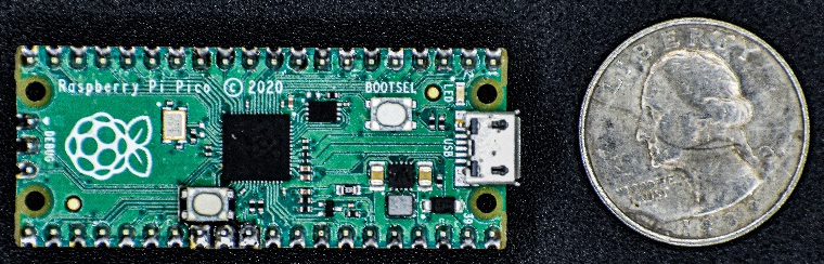
Figure 1.13 – Reset button on the Pico
The reset button makes it easier to restart the program during development. Adding a reset button is optional and it is not recommended if you are not comfortable with soldering. In the next section, we will be writing our first program for the Pico.
MicroPython
We will be using Thonny IDE (IDE stands for integrated development environment) for this example. Thonny IDE can be downloaded from https://thonny.org. The IDE is available for Windows, Mac, and Linux operating systems.
If you use a Raspberry Pi for your programming needs, it comes pre-installed with Thonny. You can launch Thonny from Menu | Programming and scroll down the drop-down button to find Thonny Python IDE, as illustrated in the following screenshot:
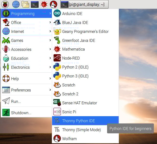
Figure 1.14 – Thonny IDE location on the Raspberry Pi Desktop
Now, let's prepare the Pico by flashing the MicroPython binary.
Flashing the MicroPython binary
The Pico needs to be connected to the computer in a specific manner to flash the banner. The steps to flash the binary are outlined here:
- The first step is to download the binary from https://bit.ly/31nBMFW.
- Press and hold the BOOTSEL button shown in the following screenshot as you connect a MicroUSB cable to your Pico. Ensure that the other end of the USB cable is connected to the computer.
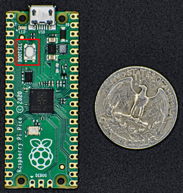
Figure 1.15 – Pico BOOTSEL button
- The Pico should enumerate as a storage device on your computer, which should look like something similar to this:
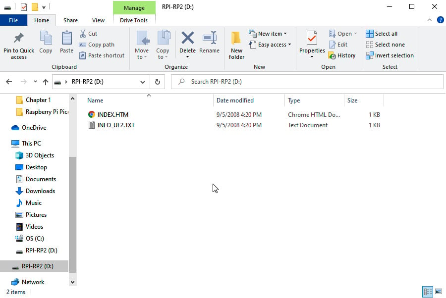
Figure 1.16 – Raspberry Pi Pico enumerated as a storage device
- Next, copy over the binary onto the storage drive. The Pico will reset itself and we are ready to write programs in MicroPython.
Now, we are ready to write our first program in MicroPython!
Writing our first program
Let's launch Thonny and take it for a test drive! You will need to take the following steps:
- Launch Thonny and you should see a window, as shown in the following screenshot:
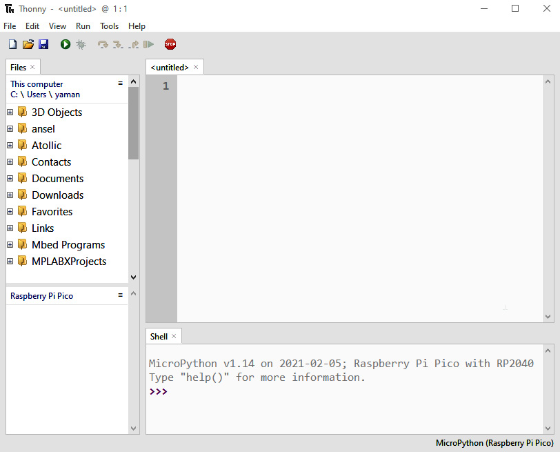
Figure 1.17 – Thonny IDE
- We are going to be running our first program using the interpreter running on your Pico. If you are not familiar with Python interpreters, they enable the testing of your code as you write them. Go to Run, and then click on Select Interpreter. From here, you will select the following options, as shown in Figure 1.18:
- MicroPython (Raspberry Pi Pico)
- < Try to detect port automatically >
These options can be seen in the following screenshot:
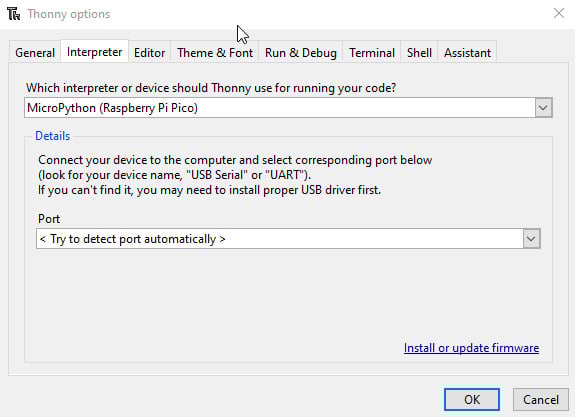
Figure 1.18 – Selecting the Python interpreter
- Now, you should see the Python interpreter, as shown in the following screenshot. This is the MicroPython interpreter running on the Pico. Let's take it for a test drive.
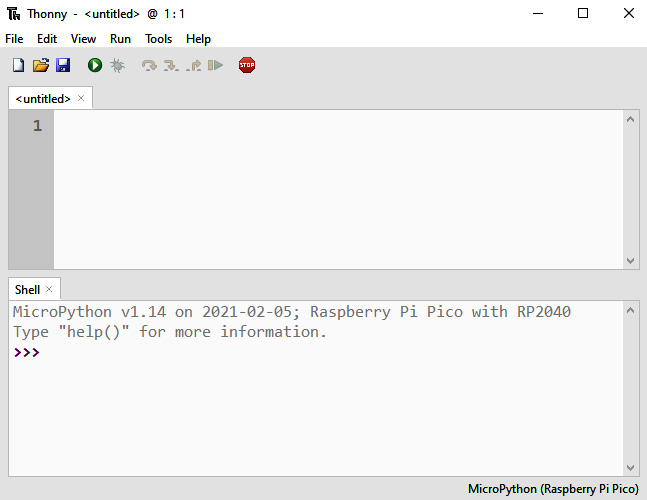
Figure 1.19 – Python interpreter
You should see the following output:
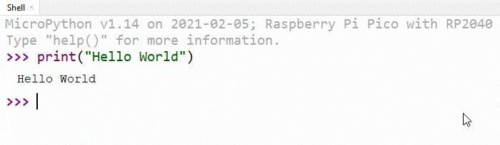
Figure 1.20 – Interpreter output
You have just finished writing your first program on your Raspberry Pi Pico! In the next example, we will write a script that starts running continuously when the Pico is powered by a USB cable.
Implementing the LED-blinking example
In the previous section, we used an interpreter to write our program. An interpreter can be helpful when testing code or finding out more information about the modules being imported. In this example, we will discuss writing a script that runs automatically on powering the Pico. We will discuss the "hello world" example of getting started with electronics where we will blink an LED at a 1-second interval.
The Pico comes with a green LED on the board and its location is shown in the following image:
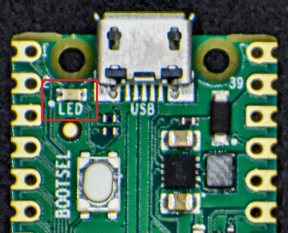
Figure 1.21 – Pico LED location
We will make this LED blink at a 1-second interval—that is, we will turn it on and off for a second. In order to write this program, we will need the machine and utime modules.
According to the Pico datasheet, the onboard LED is connected to general-purpose I/O (GPIO) pin number 25. We will proceed as follows:
- We will use the
Pinclass from themachinemodule to control the LED. - We will be using the
utimemodule to introduce the delay between turning ON and turning OFF the LED.
You will now need to take the following steps:
- Let's take a look at the following code sample:
from machine import Pin
import utime
led = Pin(25, Pin.OUT)
while True:
    led.toggle()
    utime.sleep(1)
Exercise
Develop a practice of actively using an interpreter while you are writing code. In the interpreter, import the
machineandutimemodules, try executinghelp(machine),help(utime), and find out for yourself. - Create a new file and enter the preceding code snippet shown in Step 1. Set the file location as Raspberry Pi Pico, as seen in the following screenshot to the right:
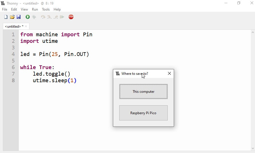
Figure 1.22 – File location
- Save the file as
main.pyand your code should automatically begin execution. - Try disconnecting the USB cable and reconnecting it. You will notice that the script starts running automatically.
- To stop the code execution, click on the STOP button located on the toolbar, as shown in the following screenshot:
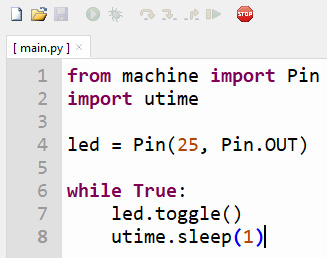
Figure 1.23 – Pressing STOP to interrupt execution
- To resume execution, click the Run Current Script button, which is indicated by the green play button indicated at the top of the page, as shown in the following screenshot:

.
Figure 1.24 – Clicking Run Current Script to resume execution
In the next section, we will take a closer look at the code.
Description of the code sample
In this section, we will discuss in detail the code sample shown previously, as follows:
- We get started by importing the
utimemodule and thePinclass from themachinemodule, as follows:from machine import Pin import utime
GPIO
A GPIO pin can be used as an input pin or an output pin. When you use a GPIO pin as an output pin, you can set it to
HIGHorLOW. Likewise, when you use it as an input pin, you can read whether the pin isHIGHorLOW. In this example, we are turning the LED on/off by alternating betweenHIGHandLOWstates. - Next, we declare the GPIO pin 25 as an output pin using an object belonging to the
Pinclass. The first argument in the following code snippet refers to the pin number (pin25), while the second argument sets the pin as an output pin:led = Pin(25, Pin.OUT)
- Now, we need to blink an LED at a 1-second interval. We are going to do this inside an infinite loop.
- The
ledobject has atoggle()function that toggles the pin between the ON and OFF states. - We will introduce a 1-second delay by calling the
sleepfunction after toggling the pin, as follows:while True: led.toggle() utime.sleep(1)
Congratulations on your first step with the Raspberry Pi Pico! Now, we will discuss the same example in CircuitPython.
CircuitPython example
In this section, we will discuss using CircuitPython for programming the Pico. We will discuss the same LED-blinking example using Pico. We will also install the Mu IDE to the program by using CircuitPython.
Flashing the CircuitPython binary
In this section, we will flash the CircuitPython binary onto the Pico. The installation process is the same as for MicroPython. The binary can be downloaded from https://bit.ly/31pnLI4.
Once you have downloaded the binary, follow the instructions from the MicroPython section.
Coding with Mu
In this section, we will install the Mu IDE. The IDE is available for download from https://bit.ly/3ruxDKW. The IDE is available for Windows, Linux, and Mac operating systems.
Raspberry Pi installation
On a Raspberry Pi, Mu can be installed as follows:
- Go to Menu | Preferences | Recommended Software | Select Mu to choose Mu from the list of software to install.
- Mu can be launched from Menu | Programming | Mu.
In the next section, we will review writing our first program with Mu.
Launching Mu
The steps to writing a program with Mu include the following:
- Connect the Pico to your computer/Raspberry Pi using a USB cable.
- Once Mu is launched, we need to set the programming mode. Since we are programming in CircuitPython, we will set it to CircuitPython, as shown in the following screenshot:
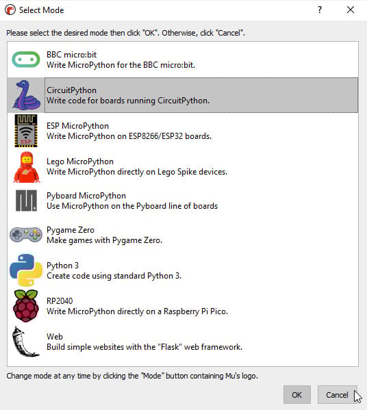
Figure 1.25 – Selecting programming mode
- You can also change the programming mode from the main window of the IDE, as shown in the following screenshot:
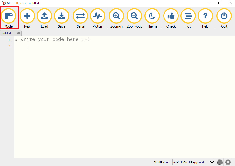
Figure 1.26 – Changing Python mode
Note the Pico being automatically detected in the preceding screenshot.
- Click the Serial button to launch access to the Python interpreter, as shown here:
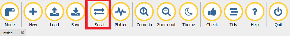
Figure 1.27 – Serial button location
- Launch the Python interpreter by pressing Ctrl + C, and it should take you to the >>> REPL prompt, as shown toward the bottom of the following screenshot:
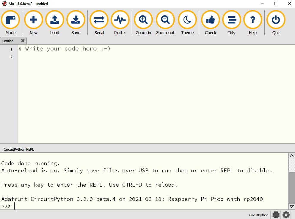
Figure 1.28 – CircuitPython interpreter on Pico
Finally, in this process, repeat the Hello World! example from the MicroPython section by using the interpreter.
Second LED-blinking example
We will discuss the same LED-blinking example using CircuitPython and observe the differences between the two flavors of Python. Let's take a quick look at the following code snippet:
import time
import board
import digitalio

led = digitalio.DigitalInOut(board.LED)
led.direction = digitalio.Direction.OUTPUT

while True:
    led.value = True
    time.sleep(1)
    led.value = False
    time.sleep(2)
Let's review the code sample, as follows:
- We get started by importing the
time,board, anddigitaliomodules. Thetimemodule is used to introduce a delay between turning the LED ON and OFF. - The
boardmodule contains definitions of the pins and peripherals specific to the board. In this example, we are making use of theLEDconstant from theboardmodule to drive the onboard LED on the Raspberry Pi Pico. - The
digitaliomodule provides access to the Pico's peripherals. In this example, we need to declare the LED pin (GPIO pin 25) as an output pin:led = digitalio.DigitalInOut(board.LED) led.direction = digitalio.Direction.OUTPUT
- In the first line of the preceding code snippet, we are declaring
ledas an instance of theDigitalInOutclass. - In the second line, we are setting the direction of the
ledpin to be an output pin. We are making use of theDirectionclass from thedigitaliomodule. - Next, we enter an infinite loop where we turn the LED on/off, as follows:
while True:
    led.value = True
    time.sleep(1)
    led.value = False
    time.sleep(2)
- In the first line of the
whileloop, we set the value to beTrue. This turns ON the LED. This is followed by a 1-second delay. This is achieved by callingtime.sleep(1). - In the third line of the
whileloop, we set the value to beFalse. This turns OFF the LED. This is also followed by a 1-second delay. - We want the script to launch upon reset. Load the
code.pyfile located on the Pico that is currently enumerated on your computer as a storage device. The Load button is located on the top toolbar. - Type the code sample we discussed into
code.pyand save it. - Press Ctrl + D from the CircuitPython interpreter and you should notice the LED blinking on the Pico.
Congratulations on writing your first CircuitPython program for the Raspberry Pi Pico!
CircuitPython or MicroPython?
In this chapter, we discussed examples with both CircuitPython and MicroPython. The examples were somewhat identical and share a similar structure. What are their differences and which flavor of Python should you use for your development?
The short answer is that it is up to you. For the sake of consistency, we will be discussing all examples in CircuitPython using the Mu IDE.
Both implementations have a wide user base and libraries for add-on hardware. CircuitPython was spun off MicroPython by Adafruit. CircuitPython can be helpful while using sensor breakout boards from Adafruit Industries.
Thonny versus Mu IDE
In this chapter, you might have noticed that we used Thonny for the MicroPython example and Mu for the CircuitPython example. We wanted to demonstrate the various tools available for the Raspberry Pi Pico. You can even use a simple text editor for your development. We will show you how to save and upload your code to the Pico.
In the next section, we will discuss add-on hardware for the Pico.
Identifying useful add-on hardware for the Pico
In this section, we will discuss the add-on hardware available for the Pico. We must note that we are only discussing hardware designed specifically for the Pico. The list is not comprehensive, and we picked examples on the basis of their differences. You are welcome to select any development board of your choosing, but this is not necessary. A simple breadboard should suffice and would be assembled as shown in the following screenshot:

Figure 1.29 – Pico on a breadboard
In the next example, we will take a look at add-on hardware where the Pico sits right next to the breadboard.
Pico Breadboard Kit (USD 19.31)
As the name suggests, this board comes with a breadboard, four LEDs, four pushbuttons, and a buzzer. There are a pair of headers to assemble the Pico onto the board and two rows of headers to access all the pins available on the Pico board. An image of the board can be seen in the following screenshot. This board can be helpful for an absolute beginner in electronics. The board can be purchased from https://bit.ly/3tV7aIa.

Figure 1.30 – Pico Breadboard Kit
The Pico breadboard can be helpful for an absolute beginner in electronics.
Pico GPIO Expansion Board (USD 10.34)
This is a development that provides access to all the pins of the Pico. There are two rows of male and female headers on both sides, as shown in the following screenshot. This board can be purchased from https://bit.ly/3rprobq.

Figure 1.31 – Pico GPIO Expansion Board
The two rows of male and female headers enable the use of male and female jumper cables for prototyping.
Pico HAT Expansion (USD 13.79)
This development board enables the interfacing of any Raspberry Pi HAT (which stands for Hardware Attached on Top) to the Pico. It comes with a 2x20 header that enables a HAT to be stacked on the board and can be seen in the following screenshot. The board also provides access to the pins of the Pico board and is connected to the HAT pinout. The board can be purchased from here: https://bit.ly/3lYRfpu. The web page also provides pin mapping from the Pico to the HAT.

Figure 1.32 – Pico HAT Expansion
This board enables a Pico to be added to your existing Raspberry Pi project. It could also enable you to use your Raspberry Pi HATs with your Pico.
Grove Shield for Pi Pico (USD 3.90)
The Grove Shield board helps to connect the Pico to the Grove ecosystem from Seeed Studio. In case you are not familiar with this, the Grove ecosystem consists of modular boards for prototyping in electronics. As you can see from the following screenshot, the board consists of a series of connectors that enables it to be interfaced to sensors and actuators. The board can be purchased from https://bit.ly/2NZG3MO.

Figure 1.33 – Grove Shield for Pi Pico
In the next example, we will discuss prototyping with stackable hardware.
Pimoroni Pico Decker (Quad Expander) (USD 16.55)
As the name suggests, this board enables the interfacing of up to four expansion boards to the Pico, as shown in the following screenshot, but it is important to ensure that there are no pin conflicts between the add-on boards. The board can be purchased from https://bit.ly/3lXpWMt:

Figure 1.34 – Pimoroni Pico Decker (Quad Expander)
In this section, we reviewed various add-on hardware available for the Raspberry Pi Pico. The list is not comprehensive—for example, Feather/Thing Plus boards come with stackable hardware known as FeatherWings. Similarly, MicroMod boards come with their own ecosystem of add-on hardware.
Summary
In this chapter, we introduced you to the Raspberry Pi Pico. We discussed the peripherals of the RP2040 microcontroller and variants of the Pico development board from other hardware manufacturers. We also discussed the add-on hardware available for the Pico. We soldered the headers for the Pico and added a reset button. We also discussed a "Hello World!" example and an LED-blinking example using CircuitPython and MicroPython.
Now that you are done setting up the Pico and have familiarized yourself with the options available to program the Pico, we will discuss the features of the RP2040 microcontroller using practical examples.
Join us in the next chapter, where we will review the communication interfaces available on the Pico!