


 Download code from GitHub
Chapter 2: Building a Traffic Lights Control System
In the previous chapter, we set up TinyGo and our IDE, and we now know how to build and flash our programs to the Arduino UNO. We are now going to utilize this knowledge to go one step further.
In this chapter, we are going to build a traffic lights control system. We are going to split the project into small steps, where we build and test each component. At the end, we are going to put everything together. We will be using multiple LEDs, a breadboard, GPIO ports, and a button to interrupt the normal flow to switch pedestrian lights to green. By the end of the chapter, you will know how to control external LEDs, read the state of a button, use GPIO ports, how to distinguish resistors, and how to utilize Goroutines in TinyGo.
In this chapter, we are going to cover the following topics:
- Lighting an external LED
- Lighting a single LED when a button is pressed
- Building traffic lights
- Building traffic lights with pedestrian lights
Technical requirements
To build the traffic lights control system, we are going to need some components. We will need the following to build the complete project:
- An Arduino UNO
- Breadboard
- Five LEDs
- Multiple jumper cables
- Multiple 220 Ohm resistors
- One push button
- One 10K Ohm resistor
You can find all code examples from this chapter in the following GitHub repository: https://github.com/PacktPublishing/Creative-DIY-Microcontroller-Projects-with-TinyGo-and-WebAssembly/tree/master/Chapter02
The Code in Action video for the chapter can be found here: https://bit.ly/2RpvF2a
Lighting an external LED
Before we start to build a more complex circuit, let's begin with lighting up an external LED. As soon as this is working, we are going to extend the circuit step by step. We begin with a single red LED. Lighting up an external LED is a bit different compared to lighting up an onboard LED. We are going to need something on which we can place the LED, and we will need some wires as well as a basic understanding of resistors, which will help us to prevent the LED from taking damage. That is why we are going to look at each component one by one.
Using breadboards
Breadboards are used for prototyping, as they do not require you to directly solder components. We are going to build all our projects using breadboards.
A breadboard typically consists of two parts:
- The power bus
- Horizontal rows
Each side of a breadboard has a power bus. The power bus provides a + (positive) lane and a - (ground) lane. The positive lane is colored red and the ground lane is colored blue. The individual slots are connected inside the power bus.
The slots of a single horizontal row are also connected. A signal in one slot is also available in the next slot. Different horizontal rows are not connected, unless we put a cable in there to create a connection. Here's what a breadboard looks like:
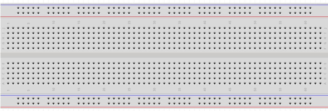
Figure 2.1 – A breadboard – image taken from Fritzing
Understanding LED basics
The Arduino UNO has an operating voltage of 5V, which is too high for most LEDs. So, we need to reduce the voltage to something our LEDs can handle. For that reason, we will be using 220 Ohm resistors to draw current from the line in order to protect the LED from damage. If you do not have 220 Ohm resistors, you can also use 470 Ohm as well; anything between 220 and 1K (1K = 1,000) Ohm will be fine.
If you want to really make sure that the resistor matches the needs of the LED, you can also calculate the resistor value as follows:
R = (Vs – Vled) / Iled
Where:
- R is the resistor value.
- Vs is the source voltage.
- Vled is the voltage drop across the LED.
- Iled is the current through the LED.
Note
LEDs have anode (+) and cathode (-) leads. The anode lead is longer.
Different colors need to be driven with different voltages. When using the same resistors and voltages for the different LED colors, you will notice that some colors will be brighter compared to others.
Using GPIO ports
GPIO stands for General Purpose Input Output. That means we can use these pins for input as well as output for digital signals. We can either set a GPIO pin to High or Low, or read a High or Low value from the port.
Note
We should never draw more than a maximum of 40.0 mA (milliampere) from a single GPIO port. Otherwise, we could permanently damage the hardware.
Building the circuit
Now let's build our first circuit on the breadboard:
- Put a red LED in the G column of the horizontal rows. Put the cathode in G12 and the anode in G13.
- Connect F12 with the ground lane on the power bus.
- Connect F13 and E13 using a 220 Ohm resistor. (Anything between 220 and 1,000 Ohms is okay.)
- Connect Pin 13 from the GPIO ports to A13.
- Connect the GND port to the ground lane on the power bus.
Note
The descriptions on your breadboard might differ from the ones I am using. If that is the case, you'll need to build the circuit by checking the next figure.
The circuit should now look like the following:
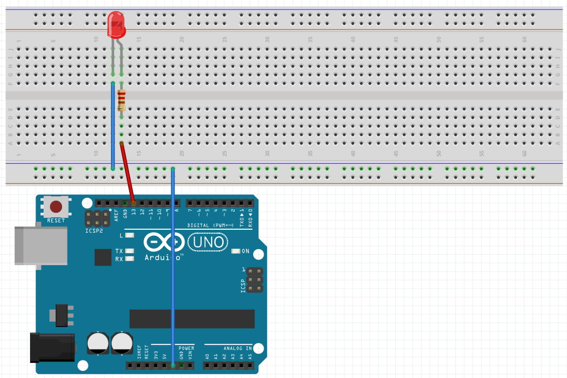
Figure 2.2 – Image of the circuit – image taken from Fritzing
Writing the code
We start off by creating a new folder named Chapter02 in our project workspace. This folder will be used for all parts of this chapter. Inside the Chapter02 folder, we create a blinky-external folder and create a new main.go file inside.
The structure should look like the following:
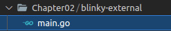
Figure 2.3 - Project structure for writing the code
We import the machine and time packages and put the following code into the main function:
- Declare and initialize a variable named
outputConfigwith a newPinConfigin output mode:outputConfig := machine.PinConfig{Mode: machine. PinOutput} - Declare and initialize a variable named
greenLEDwith a value ofmachine.D13:greenLED := machine.D13
- Configure the LED with the
outputConfiginstance we created earlier, by passing it as a parameter into theConfigurefunction:redLED.Configure(outputConfig)
- We then loop endlessly:
for { - Set
redLEDtoLow(off):redLED.Low()
- Sleep for half a second. Without sleeping, the LED would be turned on and off at an extremely high rate, so we sleep after each change in a state:
time.Sleep(500 * time.Millisecond)
- Set the
redLEDtoHigh(on):redLED.High()
- Sleep for half a second:
  time.Sleep(500 * time.Millisecond)
}
- Now flash the program using the
tinygo flashcommand using the following command:tinygo flash –target=arduino Chapter02/blinky-external/main.go
When the flash progress completes and the Arduino restarts, the red LED should blink at intervals of 500 ms.
Congratulations, you have just built your first circuit and written your first program to control external hardware! As we now know how to connect and control external LEDs on a breadboard, we can continue to build a more advanced circuit. Let's do just that in the next section.
Lighting an LED when a button is pressed
Until now, we have only used code to directly control hardware components. Let's now try to read the state of a button in order to control an LED. We will need the following components:
- At least 6 jumper wires
- One LED (the color does not matter)
- One 220 Ohm resistor
- One 4-pinned-button (push down button)
- One 10K Ohm resistor
Now let's go on to build the circuit.
Building the circuit
The following circuit extends the one we previously built. So, if you still have the previous circuit assembled, you just have to add the button part. The next circuit consists of two component groups. The first group is used to control an LED, and the second group is used to read the button state.
Adding the LED component
We start off with the LED circuit:
- Place an LED with the cathode in G12 and the anode in G13.
- Use a 220 Ohm resistor to connect F13 with D13.
- Connect port D13 from the GPIO ports with A13 using a jumper wire.
- Connect F12 with the ground lane of the power bus using a jumper wire.
Adding the button component
Now we are going to add a button:
- Use a jumper wire to connect
A31with the positive lane of the power bus. - Use a 10K Ohm resistor to connect the ground lane of the power bus with
B29. - Connect
D29with portD2. - Place the push button with one pin in
E29, one inE31, one inF29, and the last pin inF31.
Our circuit should now look similar to the following:
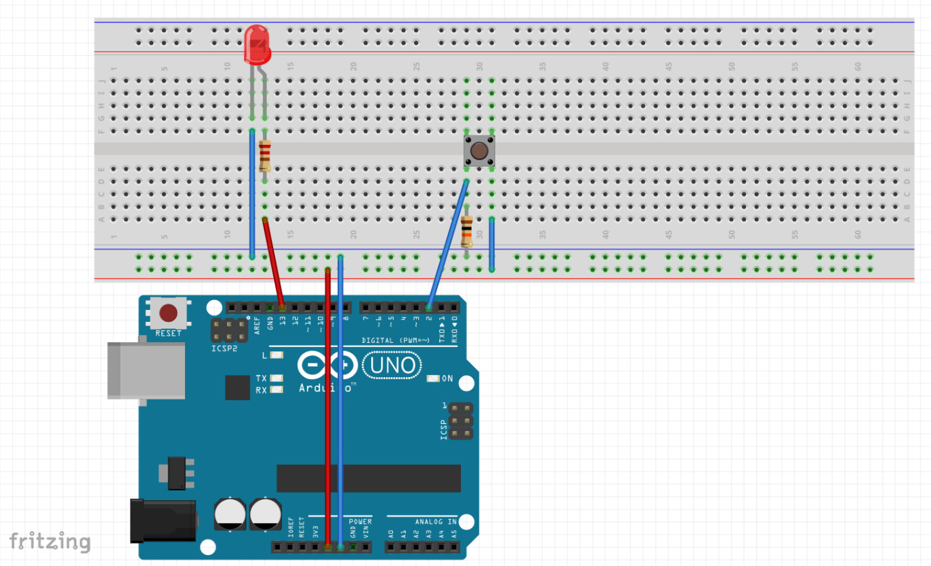
Figure 2.4 – The circuit – image taken from Fritzing
Note
Before we start to write the code for this circuit, we need to learn how these buttons work.
As the button will not work if you place it incorrectly onto the breadboard, let's have a look at the button again.
The 4 pins on the button are grouped into two pins each. So, two pins are connected to each other. Looking at the back of the button, we should be able to see that two opposing pins are connected to each other. So, the button won't work as expected when you place it rotated by 90°.
Programming the logic
Before diving into the code, we will create a new folder named light-button inside the Chapter02 folder and create a main.go file in it, with an empty main function, using the following:
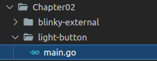
Figure 2.5 – The folder structure for the logic
Let's now look at the main function and the pull-up resistor.
The main function
We want to light the LED when the button is pressed. To achieve this, we need to read from a pin and check for its state using the following steps:
- Initialize the
outPutConfigvariable withPinConfiginPinOutputmode. This config is going to be used to control the LED pin:outputConfig := machine.PinConfig{Mode: machine. PinOutput} - Initialize the
inputConfigvariable withPinConfiginPinInputmode. This config is being used for the pin that reads the button state and therefore needs to be an input:inputConfig := machine.PinConfig{Mode: machine.PinInput} - Initialize the
ledvariable with a value ofmachine.D13, which is the pin we have connected toled:led := machine.D13
- Configure
ledas output by passingoutputConfigas the parameter, which is the pin that is connected to the button:led.Configure(outputConfig)
- Initialize the
buttonInputvariable with a value ofmachine.D2:buttonInput := machine.D2
- Configure
buttonInputas an input by passinginputConfigas the parameter:buttonInput.Configure(inputConfig)
- As we do not want the program to be terminated after checking the button state a single time, we use an endless loop to repeat and check forever:
for { - Check the current state of the button. It will be true if the button is pressed:
if buttonInput.Get() { - If the button is pressed, we light up the LED:
led.High()
- We are calling
continuehere, so we do not execute theled.Low()call:continue }
- If the button is not pressed, we turn the LED off:
    led.Low()
}
Note
Do not forget to import the
machinepackage, otherwise the code will not compile.
Now flash the program using the tinygo flash command:
tinygo flash –target=arduino Chapter02/light-button/main.go
After successfully flashing, the LED should light up when you press the button.
The pull-up resistor
You may have wondered why we need a 10K Ohm resistor in the button circuit. The 10K Ohm resistor is used to prevent the signal/pin from floating. Floating pins are bad, as an input pin in a floating state is indeterminate. When trying to read a value from a pin, we expect to get a digital value – 1 or 0, or true or false. Floating means that the value can change rapidly between 1 and 0, which happens without pull-up or pull-down resistors. Here's some further reading on floating pins: https://www.mouser.com/blog/dont-leave-your-pins-floating.
As an alternative to the 10K Ohm external resistor, an internal resistor can be used.
Configuring an input pin to use an internal resistor is done as follows:
inputConfig := machine.PinConfig{
               Mode: machine.PinInputPullup
}
We have now learned how to control an LED using an input signal, which was given by a button. The next step is to build the traffic lights flow to control three LEDs.
Building traffic lights
We know how to light up a single LED, and we also know how to light up an LED using a button input. The next step is to build a circuit using three LEDs and to write the code to light them up in the correct order.
Building the circuit
To build the circuit, we need the following components:
- Three LEDs (preferably red, yellow, and green)
- Three 220 Ohm resistors
- Seven jumper wires
We start by first setting up the components using the following steps:
- Connect GND from the Arduino to any ground port on the power bus.
- Place the first (red) LED with the cathode in G12 and the anode in G13.
- Place the second (yellow) LED with the cathode in G15 and the anode in G16.
- Place the third (green) LED with the cathode in G18 and the anode in G19.
- Connect F13 with D13 using a 220 Ohm resistor.
- Connect F16 with D16 using a 220 Ohm resistor.
- Connect F19 with D19 using a 220 Ohm resistor.
- Connect F13 to Ground on the power bus using a jumper wire.
- Connect F16 to Ground on the power bus using a jumper wire.
- Connect F19 to Ground on the power bus using a jumper wire.
- Connect port D13 to A12 using a jumper wire.
- Connect port D16 to A12 using a jumper wire.
- Connect port D19 to A12 using a jumper wire.
Your circuit should now look similar to the following figure:
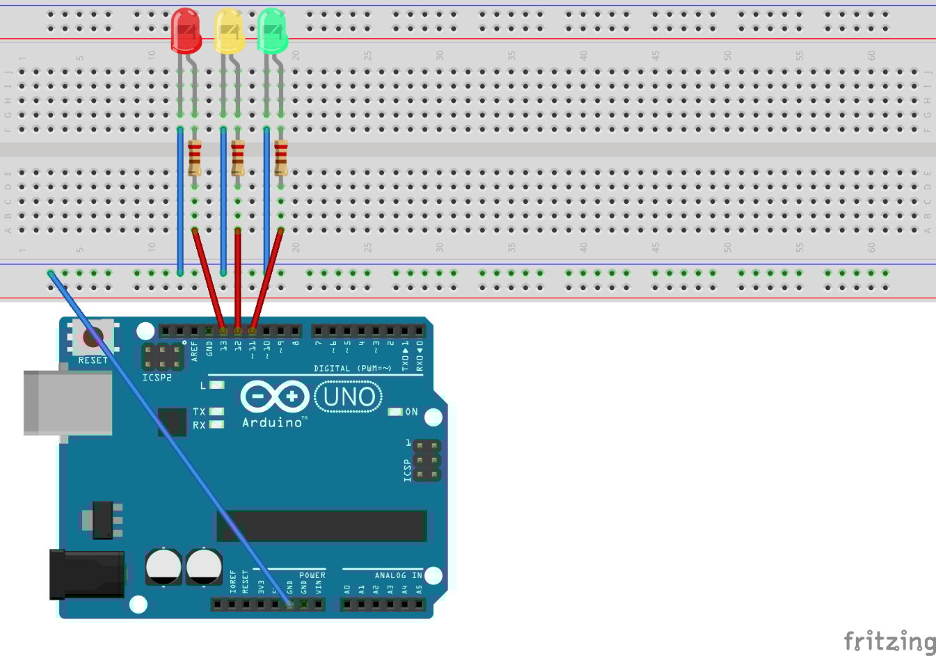
Figure 2.6 – The traffic lights circuit – image taken from Fritzing
We have now successfully set up the circuit. Now we can continue to write some code to control the LEDs.
Creating a folder structure
We start off by creating a new folder named traffic-lights-simple inside the Chapter02 folder. Also, we create a main.go file inside the new folder and start off with an empty main function. Your project structure should now look like this:
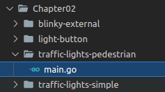
Figure 2.7 - Folder structure for the circuit
Writing the logic
We have successfully set up our project structure to continue. We are going to implement the following flow:
RED -> RED-YELLOW -> GREEN -> YELLOW -> RED
This is a typical flow for traffic lights with three bulbs.
We are going to configure three pins as output, and afterward, we want to endlessly loop and light up the LEDs in this flow.
Inside the main function, we write the following:
- Initialize a new variable named
outputConfigasPinConfigusing thePinOutPutmode:outputConfig := machine.PinConfig{Mode: machine. PinOutput} - Initialize a new variable named
redLEDwith the valuemachine.D13and configure it as output:redLED := machine.D13 redLED.Configure(outputConfig)
- Initialize a new variable named
yellowLEDwith the valuemachine.D12and configure it as output:yellowLED := machine.D12 yellowLED.Configure(outputConfig)
- Initialize a new variable named
greenLEDwith the valuemachine.D11and configure it as output:greenLED := machine.D11 greenLED.Configure(outputConfig)
We have now initialized our variables to act as output pins. The next step is to light up the LEDs in the correct order. We basically have four phases, which just need to repeat in order to simulate a real traffic light. Let's go through these one by one:
- We are going to handle the phases in an endless loop:
for { - For RED-Phase, turn on the red LED and wait for a second:
    redLED.High()
    time.Sleep(time.Second)
- For RED-YELLOW-Phase, turn on the yellow LED and wait for a second:
    yellowLED.High()
    time.Sleep(time.Second)
- For GREEN-PHASE, turn off the yellow and red LEDs and turn on the green LED and wait for a second:
    redLED.Low()
    yellowLED.Low()
    greenLED.High()
    time.Sleep(time.Second)
- For YELLOW-Phase, turn off the green LED and turn on the yellow LED, then wait for a second and turn off yellow again, so we can start cleanly with RED-Phase again:
    greenLED.Low()
    yellowLED.High()
    time.Sleep(time.Second)
    yellowLED.Low()
}
The complete content of the function is available at the following URL:
Note
Don't forget to import the time and machine packages.
We have now assembled and programmed a complete traffic lights flow. The next step is to combine everything we have built to complete our project.
Building traffic lights with pedestrian lights
We will now combine everything we have learned and done in this chapter to create an even more realistic traffic lights system. We will do so by assembling a circuit that contains the three-bulb traffic lights from the previous step and adding pedestrian lights with two bulbs that are controlled by a button.
Assembling the circuit
For our final project in this chapter, we need the following:
- Five LEDs: preferably two red, one yellow, and two green
- Five 220 Ohm resistors, one for each LED
- One 10K Ohm resistor as a pull-up resistor for our push button
- One 4-pin push button
- 14 jumper wires
We start by setting up the three-bulb traffic lights using the following steps:
- Place the first LED (red) with the cathode on G12 and the anode on G13.
- Place the second LED (yellow) with the cathode on G15 and the anode on G16.
- Place the third LED (green) with the cathode on G18 and the anode on G19.
- Use a 220 Ohm resistor to connect F13 with D13.
- Use a 220 Ohm resistor to connect F16 with D16.
- Use a 220 Ohm resistor to connect F19 with D19.
- Connect pin D13 with A13 using a jumper wire.
- Connect pin D12 with A16 using a jumper wire.
- Connect pin D11 with A10 using a jumper wire.
- Connect F12 with Ground on the power bus using a jumper wire.
- Connect F15 with Ground on the power bus using a jumper wire.
- Connect F18 with Ground on the power bus using a jumper wire.
Now assemble the pedestrian lights using the following steps:
- Place the fourth LED (red) with the cathode on G22 and the anode on G23.
- Place the fifth LED (green) with the cathode on G25 and the anode on G26.
- Use a 220 Ohm resistor to connect F23 with D23.
- Use a 220 Ohm resistor to connect F26 with D26.
- Connect pin D5 with A23 using a jumper wire.
- Connect pin D4 with A26 using a jumper wire.
- Connect F22 with Ground on the power bus using a jumper wire.
- Connect F24 with Ground on the power bus using a jumper wire.
Now we only need to assemble the button and connect the power bus:
- Place a push button with the left pins in E29 and F29 and the right pins on E31 and F31.
- Use a 10K Ohm resistor to connect the Ground from the power bus with B29.
- Connect pin D2 with C29 using a jumper wire.
- Connect A31 with the positive lane on the power bus using a jumper wire.
- Connect the positive lane on the power bus with the 5V port on the Arduino UNO using a jumper wire.
- Connect the ground lane on the power bus with a ground port on the Arduino UNO using a jumper wire.
When you've finished assembling, your circuit should look like this:
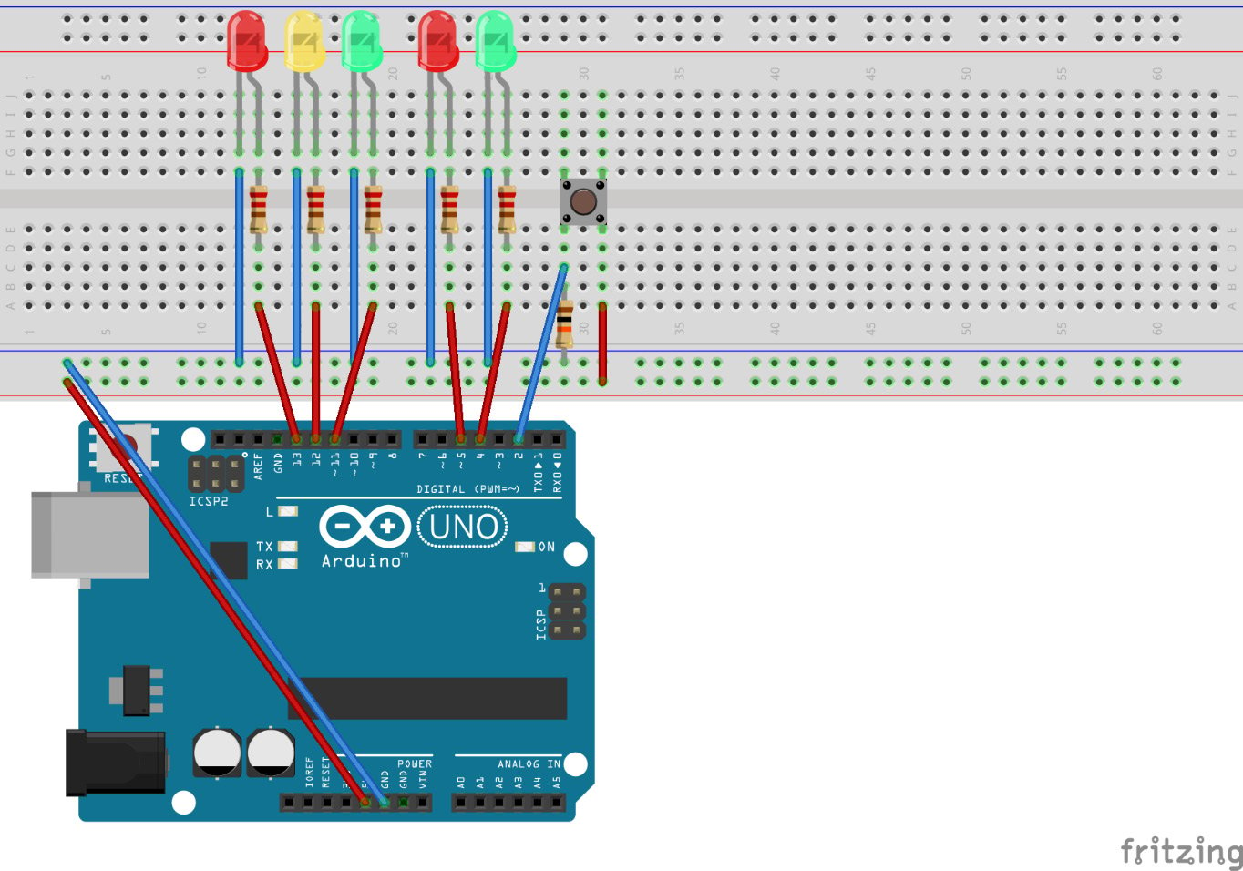
Figure 2.8 – Circuit for the traffic lights with pedestrian lights controlled by a button – image taken from Fritzing
Great, we have now completely assembled our final project for this chapter. We can now write some code to bring this project to life.
Setting up the project structure
We start off by creating a new folder named traffic-lights-pedestrian inside the Chapter02 folder. Inside the new folder, we create a new main.go file with an empty main function.
Our project structure should now look like the following:

Figure 2.9 - Project structure for the project
Writing the logic
We are going to split the program into three parts:
- Initialization logic
- Main logic
trafficLightslogic
Initializing the logic
We need to initialize a stopTraffic variable and configure the pins for the LEDs as output pins using the following steps:
- We start off by declaring a
boolvariable namedstopTrafficat the package level. This variable is going to be used as a communication channel between our two logic parts:var stopTraffic bool
- The first thing we do in the
mainmethod is set the value ofstopTraffictofalse:stopTraffic = false
- We declare and initialize a new variable named
outputConfigwithPinConfiginPinOutputmode. We are going to pass this config to all LED pins:outputConfig := machine.PinConfig{Mode: machine. PinOutput} - We initialize some new variables:
greenLEDwith the valuemachine.D11,yellowLEDwith the valuemachine.D12, andredLEDwith the valuemachine.D13. Then, we configure each LED variable as output pins:greenLED := machine.D11 greenLED.Configure(outputConfig) yellowLED := machine.D12 yellowLED.Configure(outputConfig) redLED := machine.D13 redLED.Configure(outputConfig)
- We initialize some new variables:
pedestrianGreenwith the valuemachine.D4andpedestrianRedwith the valuemachine.D5. Then, we configure each LED variable as output pins:pedestrianGreen := machine.D4 pedestrianGreen.Configure(outputConfig) pedestrianRed := machine.D5 pedestrianRed.Configure(outputConfig)
- We declare and initialize a new variable named
inputConfigwithPinConfiginPinInputmode. Then, we declare and initialize a new variable namedbuttonInputwith the valuemachine.D2and configurebuttonInputas the input pin:inputConfig := machine.PinConfig{Mode: machine.PinInput} buttonInput := machine.D2 buttonInput.Configure(inputConfig)
That's it for the initialization. We have set up all pins and a Boolean variable at the package level.
Note
The pin constants, such as machine.D13, are of the machine.Pin type.
Writing the trafficLights logic
We will now write the complete logic to control all the LEDs in our circuit. This is going to be the first time that we have to move some parts of the code into other functions.
To do that, we start by writing a new function named trafficLights that takes all five LED pins as parameters and has no return value. Inside the function, we start off with an empty, endless loop. Our function should now look like the following:
func trafficLights(redLED, greenLED, yellowLED, pedestrianRED,
    pedestrianGreen machine.Pin) {
      for {
      }
}
All the logic will be placed inside the for loop. The actual logic in the loop consists of two parts:
- Handling signals from the button to stop the traffic and control the pedestrian lights
- Controlling the normal traffic lights flow
We start off with handling the signals from the button. To do that, we check for stopTraffic in the if, and also have an empty else branch. It looks like the following:
        if stopTraffic {
    } else {
}
So, when stopTraffic is true, we want to set our traffic lights phase to be red. Also, we want to set the pedestrian lights phase to green for 3 seconds and then back to red and set stopTraffic to false afterward, as we handled the signal one time.
Let's implement this logic using the following steps:
- Set traffic lights phase to red:
redLED.High()
yellowLED.Low()
greenLED.Low()
- Set the pedestrian lights phase to green for 3 seconds:
pedestrianGreen.High()
pedestrianRED.Low()
time.Sleep(3 * time.Second)
- Set the pedestrian lights phase to red:
pedestrianGreen.Low()
pedestrianRED.High()
- Set
stopTraffictofalse, as we have handled the signal:stopTraffic = false
- In the
elseblock, we just reset the pedestrian lights state to red:pedestrianGreen.Low() pedestrianRED.High()
Okay, that is the part that reacts to stopTraffic signals. Underneath that if-else block, we are going to implement the actual logic to control the traffic lights flow, which is the same as done earlier. So, we start with the red phase, transit to the red-yellow phase, then to green, then to yellow, and then reset yellow to be able to start clean again, as follows:
redLED.High()
time.Sleep(time.Second)
yellowLED.High()
time.Sleep(time.Second)
redLED.Low()
yellowLED.Low()
greenLED.High()
time.Sleep(time.Second)
greenLED.Low()
yellowLED.High()
time.Sleep(time.Second)
yellowLED.Low()
That is all that we have to do in the trafficLights function.
Implementing the main logic
Now we only need to run the trafficLights function and handle the button input at the same time. This is where goroutines come in. As microcontrollers only have one processor core, which works with a single thread, we cannot have real parallel execution of tasks. As we use goroutines on an Arduino UNO, we will need some additional build parameters. We are going to learn about these parameters later, when we flash the program. In our case, we want to have a listener on the button, while still being able to step through the traffic lights process. The logic consists of three steps:
- Initialize the pedestrian lights with the
redphase. - Run the
trafficLightsfunction in a goroutine. - Handle the button input.
For the first part, we only have to set the pedestrianRED LED to High and the pedestrianGreen LED to Low:
pedestrianRed.High()
pedestrianGreen.Low()
Now we just call trafficLights and pass all necessary parameters using a goroutine:
go trafficLights(redLED, greenLED, yellowLED, pedestrianRed, pedestrianGreen)
For the last step, we need an endless loop that checks for buttonInput and to set stopTraffic to true if the button is pressed. We also need it to sleep for 50 milliseconds afterward:
for {
  if buttonInput.Get() {
    stopTraffic = true
  }
  time.Sleep(50 * time.Millisecond)
}
Note
It is necessary to add a sleep time to the loop that handles the button input because the scheduler needs time to run the goroutine. The goroutine is being handled in the time that the main function is sleeping. Also, other blocking functions, such as reading from a channel, can be used to give the scheduler time to work on other tasks.
As we now have completed our logic, it is time to flash the program onto the controller. As we are using goroutines in this project, we need to pass additional parameters to the tinygo flash command:
tinygo flash -scheduler tasks -target=arduino Chapter02/traffic-lights-pedestrian/main.go
As the ATmega328p has very limited resources, the scheduler is deactivated by default on boards that use this microcontroller. The Arduino UNO is such a board. When using other microcontrollers, we would normally not need to override the default scheduler by setting this parameter.
We have now successfully flashed our program to the Arduino Uno. The traffic lights should start looping all phases and the pedestrian lights should remain in the red phase. When clicking the button, the traffic lights should end their loop and then the pedestrian lights should switch to the green phase, while the traffic lights remain on the red phase for 3 seconds.
Note
Due to the very limited memory on the Arduino Uno, working with goroutines might only work in projects that are not very complex, such as this one.
Summary
We have learned how to build a fully functional traffic lights system with pedestrian lights controlled by a button. We achieved this by building each part of the project separately and assembling it all together at the end.
We learned how to use breadboards, how the color codes on resistors work, why we use resistors when controlling LEDs, and how external LEDs are assembled. Also, we learned how to use push buttons, how to prevent floating signals using pullup resistors, and how to utilize goroutines in TinyGo.
In the next chapter, we are going to learn how to read input from a 4x4 keypad and how to control a servo motor. We are going to utilize this knowledge to build a safety lock that opens when the correct passcode is entered.
Questions
- Why do we place a resistor between an LED anode and the GPIO port?
- How do we stop a signal from floating?
- Why do we sleep after checking a button's state?
- How would you modify the code to achieve the following behavior?
a. When the button is pressed, turn off the red and green LEDs of the traffic lights and let the yellow LED blink.
b. When the button is pressed again: go back to the normal phase rotation.
Further reading
- Resistor Color Conversion Calculator: https://www.digikey.com/en/resources/conversion-calculators/conversion-calculator-resistor-color-code
- Goroutines in TinyGo: https://aykevl.nl/2019/02/tinygo-goroutines