


In this chapter, you are going to set up some XBee modules and send your first couple of bytes wirelessly. You will see how to wire up an XBee module, how to flash and configure it using the XCTU program, and how to manually transmit data. You will also learn about ZigBee networks, addressing, and network formation.
To follow the examples, the following components are recommended:
Two XBee ZB modules (sometimes called "Series 2" modules, ordering code XB24-Z7xIT-xxx, https://www.sparkfun.com/products/11217).
One SparkFun XBee Explorer USB adapter (https://www.sparkfun.com/products/11812).
One SparkFun XBee shield (https://www.sparkfun.com/products/12847). Do not forget the stackable headers if they are not included with the shield.
One Arduino Uno r3 (https://www.arduino.cc/en/Main/ArduinoBoardUno).
Together, they will look like this:
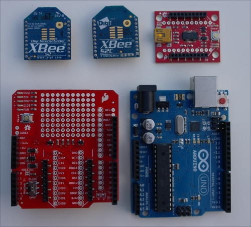
Note that the XBee ZB modules mentioned will likely be replaced by a newer version soon (ordering code XB24CZ7xIT-xxx). One of the modules shown in the preceding photograph is the new S2C module, the other is the older S2 module.
The first two chapters include instructions on using other types of hardware too, so if the preceding hardware items are not easy to obtain, or you want to use different hardware for another reason (because you need features offered by other XBee modules, or you want to save a bit of money by using a second shield instead of the SparkFun Explorer board), read these two chapters first before you decide what to order.
If you run into problems at any time during this chapter, you could refer to Chapter 2, Collecting Sensor Data, which contains more details on how to connect XBee modules and has a troubleshooting section.
For connecting multiple Arduino boards wirelessly, there are numerous add-on boards and modules available. Options range from simple low-power 433Mhz transmitters that offer raw radio access, and require everything from addressing and error correction to encryption to be done on the Arduino, to complex modules that take care of all radio processing, encryption, and mesh routing (and even include a programmable microcontroller).
This book will focus on the XBee modules manufactured by Digi International. These modules are easy to use, well supported by Arduino libraries, and not too expensive. Digi offers a number of different XBee product families, each with unique features and transmission range. Since all the XBee modules have a similar serial interface, configuration values, and hardware pinout, they are largely interchangeable. Advice and experience that apply to one often also apply to the others.
Here is an overview of all the XBee product families that Digi currently produces and that use the common XBee through-hole pinout (a few other families use a surface-mount design, but these are not discussed here):
XBee and XBee-PRO 802.15.4: These modules let you use the radio protocol defined in the IEEE 802.15.4 standard directly. This is a fairly simple protocol designed for low-power, low-data-rate communication. It operates in the 2.4Ghz spectrum, just like Wi-Fi (defined in the IEEE 802.11bgn standards), but is a lot simpler, has a lower throughput, and has a much lower power usage. These modules support no (mesh) routing: only modules that can directly hear each other can communicate.
XBee and XBee-PRO ZB: These modules use the ZigBee Pro radio protocol for communicating. ZigBee is a layer on top of 802.15.4 that adds mesh routing and extended network management capabilities. Mesh routing allows two modules to communicate even when they are not within range of each other, by letting other modules forward data on their behalf.
On top of basic communication, ZigBee application profiles define standard messages and commands to allow, for example, remote-controllable lamps, switches, or other equipment from different manufacturers to interoperate.
XBee and XBee-PRO DigiMesh 2.4: These modules run a proprietary mesh protocol developed by Digi, also in the 2.4Ghz spectrum. This protocol is comparable with ZigBee, but important differences are that all nodes are equal, can do routing, and even routing nodes can sleep to save power. These modules use the same S1 hardware as the XBee 802.15.4 modules, so each can be converted to the other by replacing the firmware version.
XBee-PRO 900HP: These modules run in the lower 900Mhz spectrum, giving them an extended range (up to 14km line-of-sight) and making them less sensitive to obstacles than the 2.4Ghz modules. They also use the proprietary DigiMesh protocol. Due to regulatory limitations, these modules are only usable in North America and a few other selected countries.
XBee-PRO 868: These modules run in the lower 868Mhz spectrum, allowing up to 40km line-of-sight range. These modules do not use any meshing protocol; instead, they employ a proprietary protocol that only allows direct communication between modules. Due to regulatory limitations, these modules are only usable in Europe.
XBee Wi-Fi: These modules use the common Wi-Fi protocol (802.11bgn). By default, these modules join the network of an existing access point, but they can also be configured to run as an access point, run an ad-hoc network, or use Wi-Fi Direct. Due to the nature of Wi-Fi, no mesh routing is supported and power usage is significantly higher than, for example, the XBee 802.15.4 and XBee ZB modules; however, throughput can also be a lot higher.
Sometimes you will also see the terms Series 1, which is the name originally used for the XBee 802.15.4 family, and Series 2, which is a retired family that used the same hardware as XBee ZB but with a different firmware (ZNet 2.5) and radio protocol. This old naming is still reflected in the names used for individual hardware boards, which use names such as S1, S2, S2B, and so on.
As noted earlier, some modules are available in normal and PRO variants. These PRO modules use the same radio and serial protocol as the regular modules, but feature a more powerful transmitter and more sensitive receiver, allowing for a significantly extended range (and also requiring more power, of course). Since the radio protocol is the same, the normal and PRO modules of the same family can be intermixed.
Most of the XBee modules are available in a few different versions, differing only in the antennae they use. The easiest are the PCB antenna, which uses copper on the circuit board as the antenna, and the wire antenna, where a short piece of wire sticks up from the board. Both have similar performance. There are also modules available with a u.FL or RPSMA antenna connector, allowing them to have an external antenna (useful for projects inside a box, needing maximum reception). When in doubt, get the PCB antenna version, as it is the least fragile and performs well.
For a few more details about the available boards, also see this guide from SparkFun: https://www.sparkfun.com/pages/xbee_guide.
Note
In the XBee ZB context, Pro can have two different and unrelated meanings, which can be confusing.
On the one hand, the XBee-PRO modules are more powerful versions of the regular modules. This is a distinction made by Digi in their hardware model names.
On the other hand, ZigBee Pro is the protocol used by the XBee ZB (and XBee-PRO ZB) modules. The latest version of the ZigBee specification, ZigBee-2007, defines two variants: Normal ZigBee and ZigBee Pro. ZigBee Pro is a bit more complicated, allowing for networks to scale to thousands of devices. Compatibility between these variants is limited; for this reason, most devices implement ZigBee Pro and the "normal" ZigBee protocol is not used very much.
In this book, all examples (and most of the discussion) focus on the XBee ZB modules, but most of the material presented also applies to the other modules. Where significant differences occur, these will be noted and (concise) instructions for other module types will be given. Therefore, if you decide to use the XBee 802.15.4, XBee DigiMesh 2.4, or XBee-PRO 868 modules (or any of the PRO variants), you can still work through this book normally. The XBee-PRO 900HP modules are not discussed in this book, but these are expected to work in a very similar way to the DigiMesh modules.
Instructions for the Wi-Fi modules are not included, since the setup and operation of Wi-Fi are significantly different from the other modules. However, a lot of the more general information (API frame format, XCTU operation, and AT commands) applies equally to these modules.
For each of the XBee module series, Digi publishes a lot of documentation. This documentation can be accessed from the Digi website, through the Support section. The most important document is the Product Manual, which contains info on the hardware, network setup, a full list of commands and API frames supported, and so on.
Even though all the information you need for these examples is included in this book, you are encouraged to get familiar with the product manual for your XBee modules as well. The manual will be a lot more detailed in some areas and is easy to use as reference material for commands, configuration values, frame types, and so on.
Note that, within the ZigBee ZB family, there is a division between older boards (using S2 or S2B hardware) and newer boards (using S2C hardware). These boards are largely compatible, but there are two separate product manuals available with largely identical content (which are both titled Product Manual: XBee / XBee-PRO ZigBee RF Modules). Be sure to get the right one for your boards.
In this section, you will send your first messages between two XBee modules. The first module will be attached to your computer through the XBee Explorer USB board, using the XCTU program to talk to it. To remove the need for a second Explorer board just for this example, the second module will be connected to an Arduino, which will simply print all data received through the serial monitor.
To let your XBee modules start a network, you will need to have exactly one coordinator module, and one or more router modules (the difference between these will be discussed later). XBee modules will usually default to being a router, so you will need to switch one into coordinator mode, as shown next.
This chapter will show brief instructions on connecting things with the recommended hardware. It is possible to use different hardware too, but it is recommended you read on until the first part of the next chapter, since that contains more details on how the connection actually works and what you should be aware of when figuring out how to connect your hardware.
This is by far the easiest way to connect an XBee module: just plug in the XBee module and connect the USB cable:

Be sure to disconnect the power (USB cable) when changing connections, or (un)plugging XBee modules into adapters and shields, to avoid damaging them.
You might have to install drivers for the FTDI USB-to-serial chip used by the Explorer, though this should have been taken care of if you have already installed the Arduino IDE (the older Arduino boards use the same chip and drivers). See the SparkFun site for more information on using the Explorer boards (https://learn.sparkfun.com/tutorials/exploring-xbees-and-xctu) or installing the FTDI drivers (https://learn.sparkfun.com/tutorials/how-to-install-ftdi-drivers).
If the drivers are installed correctly, a new (virtual) serial port will be made available; you can select it in the XCTU program later.
XBee configuration and test utility (XCTU) can be downloaded from http://www.digi.com/xctu. In this book, the Next Generation XCTU, version 6.2.0, was used, but using the newest version available is recommended. Starting with this 6.2.0 version, Linux is supported in addition to Windows and OS X.
After running through the installer and starting XCTU, the first step is to add a module that tells XCTU which serial port to connect to, and what settings to use. There are two buttons for this:

You will normally use the left Add devices button, which asks you for the settings to use. The right Discover devices button can be used when you are not sure about the right settings to use. Though it is not as magical as it sounds (you still need to select the serial port to use and select what different settings to try), XCTU will simply try all settings one by one until it finds one that works.
Go ahead and click on the left button. You will be greeted by a window where you can select the serial port and enter settings:

The serial port you need to use depends a bit on the platform. On Windows, it is likely the highest COM port listed (described as USB Serial Port). On OS X, it will look like usbserial—xxxxxxxx and, on Linux, it will be ttyUSBx. Unplugging your Explorer and refreshing the list is an easy way to figure out what port belongs to it.
By default, XBee modules are configured for 9600 baud, 8N1, so you can probably just leave all settings at their default, as shown in the preceding screenshot, and click on Finish right away. XCTU will open up the serial port and start talking to your XBee module to find out its type and firmware version. Shortly afterwards, the left side of the screen should show your module's information. If you click it, XCTU will further query your module for its current configuration settings. You should have something that looks somewhat like this:

On the right part of the screen, you see what is called the Configuration working mode by XCTU. It shows all the current configuration values and lets you change them. If you change any of the values, they will not be sent to the device until you tell XCTU to write the changes. You can write all changed settings at once by clicking on the Write radio settings button at the top:

Alternatively, you can write just a single setting by clicking on the Write button next to the setting.
Note that both buttons update the current value in the module and let the module write the values to its non-volatile memory (so they are remembered across a power cycle).
In the rest of this book, when a configuration value is mentioned, this is the place to go to. All configuration values have a two-character name, so you will often see something like Set EE=1, meaning you change the EE configuration value to the value 1, and then write the new configuration to module by pressing the Write button.
Note
All numerical configuration values in XCTU are entered in hexadecimal (see this article if you are unfamiliar with hexadecimal numbers: https://learn.sparkfun.com/tutorials/hexadecimal). In this book, hexadecimal numbers are usually shown using the 0x prefix for clarity, but that prefix must be removed when entering values in XCTU.
As a first step in preparing your module for operation, you should check, and potentially replace, its firmware. For XBee ZB S2/S2B modules, this is needed to switch between different modes of operation, but for other modules it also makes sense to ensure your module is running the latest available firmware version.
The firmware is a bit of software, written by the manufacturer, that controls the XBee modules internally. It is responsible for operating the radio, taking care of the 802.15.4, ZigBee, and/or DigiMesh protocol processing (as well as any encryption), and communicating the results on the serial port.
For most XBee modules, there are several variants of the firmware, each with a slightly different function set. Some of these provide different features, but others are intended for hardware only. For now, you should just use the function set indicated next, but by the end of this chapter you will know what most of the function sets listed mean exactly.
To replace the firmware, some special commands have to be sent through the serial port to start the boot loader, which is a small piece of low-level software running on the XBee module that takes care of firmware updates. After starting the boot loader, the firmware file can be transferred through the serial port. Fortunately, there is no need to take care of this manually—the XCTU program can mostly handle firmware updates automatically.
To initiate a firmware update, select the module on the left, and click on the Update firmware button:

A window pops up, allowing you to select the Product family, Function set, and Firmware version. The right product family should already be selected (take a note of which one is selected in case you need to do recovery later). The first module will be the coordinator, so select the ZigBee Coordinator AT function set when using an XBee ZB S2 or S2B module, or ZIGBEE Reg function set when using S2C (where Reg is for Regular and indicates that this is not XBee-PRO). Finally, select the highest version listed to use the most recent firmware version.
You should probably also uncheck the Force the module to maintain its current configuration checkbox, in order to ensure you start with a clean factory default configuration.
Your selection should look like this:

By clicking on Update, the XCTU program will start replacing the current firmware with the one selected. This takes around half a minute to complete; be sure not to unplug the board during the process.
Note
Version numbers for XBee modules are a bit confusing at first glance. They consist of four hexadecimal digits. Of these digits, the second digit is not really part of the version number, but indicates the function set used. For example, at the time of writing, 21A7 is the most recent ZigBee Coordinator API version, while 23A7 is the most recent ZigBee Router API version. This might suggest that the router API firmware is more recent, but both of these are equally recent and based on the same codebase; they just use a different function set.
Furthermore, the third digit indicates whether this is a stable (even) or beta (odd) version. The previously listed versions are stable, since their third digit is even (0xA = 10).
Note that, when you replace an existing coordinator's firmware, it will also start a new network. If other XBee modules previously joined the coordinator's network, it is possible that these are now joined to the old network and will no longer talk with the new coordinator. You can check by looking at the OI configuration value, these should be equal on all modules. The easiest way to force the router to leave the old network, is to change its ID configuration value, click the Write button, then change ID back to its previous value and click Write again. Doing this on the router(s) after you change the coordinator's firmware should prevent issues.
Replacing the firmware is not entirely without risk. If the process is interrupted, or fails for some other reason, there is a chance that the module will end up without a working firmware. This prevents the module from working normally, but also prevents a subsequent firmware update from being started in the normal way.
If the regular firmware is broken, recovery requires connecting the XBee to your computer with hardware flow control (RTS/CTS) lines connected. The SparkFun Explorer USB board supports this out-of-the-box, but see this page for information on using an Arduino Leonardo for configuration and recovery: http://www.stderr.nl/Blog/Hardware/Electronics/Arduino/XBee/XctuAndArduino.html.
For exhaustive instructions on this recovery procedure, refer to the Digi knowledge base (search for XBee recovery).
For this initial example, only minimal configuration is needed:
The first module must be set to be a coordinator. When using the XBee ZB S2 or S2B modules, this is already done by uploading the coordinator firmware. When using the S2C modules, you will have to set
CE=1(Coordinator Enable) to turn the first module into a coordinator.The destination address for transmissions must be configured. This is determined by the
DHandDL(Destination High and Low) configuration values. Together, they contain a 64‑bit address of the destination (read on for more info on these addresses). For this example, it is best to setDH=0andDL=0xFFFF, causing messages to be broadcast to all other nodes.
For example, to change the destination address:
Make sure you are in the Configuration working mode using the button at the top right.
Scroll down the list of configuration values in the right part of the screen, until you find the Addressing section.
Set
DHto the value0andDLtoFFFF(leaving out the0xpart).Finally, click on the Write radio settings button above the list to apply the changes.
Setting CE is similar, but the value can be found in the Networking section instead.
Now, to talk to your XBee module, you can use the serial console built into XCTU (using another serial program is also possible, but do not forget to disconnect in XCTU first). To do so, head over to the Consoles working mode by clicking on its button at the top right:

Then click on the Open connection button in the top left of this area to enable the console:

The console is divided into two parts horizontally. The left side shows all data sent (blue) or received (red) as text and lets you type text to be sent. The right shows the same, but shows each byte value in hexadecimal.
Go ahead and type something in the left area. Anything you type there will be sent to the XBee module, which will then directly send the data through the radio again. So, you have sent your first radio message now, even though there is nobody listening yet.
To allow configuring the module, a special command mode
is supported too (this is what is used under water when you change a configuration value in XCTU). By default, this command mode can be entered by sending a special sequence to the XBee module: a pause of at least 1 second, three iterations of a plus sign (+++, no Enter), and another pause of at least 1 second. When command mode is entered, the XBee module will reply with OK, and commands can be sent to the XBee module, terminated by a newline. These commands all start with AT, inspired by the Hayes command set originally designed for dial-up modems. Since these commands use normal text, it is easy to interact through AT mode simply by using a serial terminal. When no command is given for a while (10 seconds by default), the module leaves command mode again.
Try entering command mode and giving the ATVR command (do not forget to press Enter), which should retrieve the current firmware version:

Now you have set up an XBee module to transmit data, the next step is to receive this data again on another module. The default firmware and configuration are probably sufficient for this but if they do not work, connect the second module to XCTU using your Explorer board and update the firmware to the ZigBee Router AT version (XBee ZB S2/S2B only) and check the DH and DL values.
To set up your second XBee module, you will use an Arduino Uno and the SparkFun XBee shield to forward all received data to the computer. Again, if you want to use different hardware, skip ahead to Chapter 2, Collecting Sensor Data, which has more details on how to connect an XBee module to an Arduino and how to modify the sketch to support a different setup.
The sketch used for receiving data is available in the code bundle as SerialDump.ino. The exact contents of the sketch will not be discussed here, though you are encouraged to look inside to see what happens. Basically, the sketch opens up a serial connection to the XBee module at 9,600 bps (bits per second), and a serial connection to the computer at 115,200 bps. Any data received from the XBee module is forwarded to the computer, both in hexadecimal and readable ASCII format.
This sketch uses the AltSoftSerial library, so be sure to install that through the library manager, or download it from https://www.pjrc.com/teensy/td_libs_AltSoftSerial.html.
To connect the XBee module to your Arduino, you will use the SparkFun XBee shield. To allow talking both to the computer and the XBee at the same time reliably, you will need some trickery to connect the XBee's serial pins to AltSoftSerial's pins 8 and 9. This will be explained in more detail in Chapter 2, Connecting Sensor Data, but for now:
Put the switch on the shield into the
DLINEposition.Connect pin 2 to pin 8 and pin 3 to pin 9 on the shield.
Insert the XBee module.
This should look a bit like this:

To actually receive data, open up the serial monitor in the Arduino IDE and configure it for 115200 baud. Now head back to the console in XCTU and type a message to be sent:

It is best to first type the message in a text editor, such as Notepad, and then paste it into XCTU. This makes sure the entire message is sent in a single radio packet. If you type in XCTU directly, each letter will be put into its own packet, which can cause delays and, when broadcasting, even mess up the ordering of letters in some circumstances.
In the serial monitor, you should see the same message being received:
Starting....
48 65 6C 6C 6F 2C 20 77  Hello, w
6F 72 6C 64 21           orld!
As you can see, any data sent to the XBee module on the sending side is reproduced byte-for-byte identically on the receiving side. For this reason, this mode of operation is commonly called transparent mode and can be useful to quickly make an existing serial connection wireless.
The sketch also allows typing a message into the serial monitor, which will be sent to the XBee module and then on to the other XBee module, and is shown in XCTU, so go ahead and try that too.
Until now, you have seen the XBee module work in AT mode or transparent mode. Any data the XBee module receives on its serial port is transmitted as it is by the radio, and any data received by the radio is forwarded through the serial port directly.
AT mode can be useful for simple point-to-point radio links, or when talking to existing serial devices (where you have no control over the serial protocol used). Transparent mode can also be used to upload sketches to a remote Arduino through the air (not covered in this book). Most examples and tutorials available on the Internet use this transparent mode for communicating.
However, AT mode is also limited. Data can only be sent to a single preconfigured address. When receiving data, there is no indication as to the source of a received byte. Furthermore, when receiving data from multiple nodes, their messages might end up being interleaved if no special care is taken. Finally, AT mode does not support sending more advanced ZigBee messages, which are needed to interoperate with some existing ZigBee devices—for example, using the ZigBee Home Automation protocol.
To alleviate these limitations, the XBee modules support API (Application Programming Interface) mode. In this mode, all serial communication uses a binary protocol, consisting of API frames (also called API packets). Each of these frames starts with the 0x7E byte to indicate the start of the frame and contains a frame length, a checksum, a frame type, and extra type-specific data.

Examples of frames that can be sent to an XBee module are Transmit Request and AT Command; examples of frames sent by the XBee module are Receive packet, AT Command Response, or Modem status.
Each of these frame types has its own structure, containing a number of parameters that indicate the operation that should take place, or the event that occurred. If you look at the Transmit request frame, for example, this contains a field for the destination address, some transmission options, and the actual data to send.
Because of this format, it is easy to send data to different nodes, without having to change any configuration. Since data received is similarly wrapped in frames, you will know about the source of every message received too, which allows you to build more complex networks.
Because API mode uses a binary frame format, it is a bit harder to talk to the XBee module manually (you cannot just open up a serial console and start typing like you did before). However, for configuration and testing, the XCTU utility can take care of the frame generation and parsing for you; on the Arduino, there is a good library to do this.
For the XBee ZB S2/S2B modules, there is a separate firmware for AT mode and for API mode. To switch from AT mode to API mode, or vice versa, you have to replace the firmware. For the other XBee modules (including the XBee ZB S2C), a single firmware can run in both modes. Using the default setting of AP=0, they run in AT mode; however, by configuring AP=1 or AP=2, they run in API mode. There are two variants of API mode: with (AP=2) and without (AP=1) escaping some special characters (see the product manual for how exactly this escaping works).
In the rest of this book, all XBee modules will be configured for API mode with escaping enabled (AP=2), for maximum flexibility and robustness for your sensor network (note that the Arduino library used currently requires the use of escaping too). AT mode will not be covered in this book beyond what you have seen so far, but check out the product manual and resources online for more info on AT mode if you need it.
To take advantage of API mode, you will need to configure your modules to use it. First, try switching your coordinator to API mode:
For XBee S2/S2B modules, replace its firmware with the ZigBee Coordinator API version, as shown earlier. This step is not needed for other modules.
Remember to change
IDand change it back again on the other XBee module when you replace the coordinator's firmware, to force the other module to join the new network.Set
AP=2to enable escaping. XCTU will detect that escaping mode is now enabled and automatically applies the escaping to all data it sends and receives.
With this change, the XBee module will no longer allow typing of messages directly into the serial console, but expects to receive properly formatted API frames instead.
To send these frames, head over to the Consoles working mode at the top-right again. Click on Open connection like before to connect to your XBee module.
You will notice that the window looks different from before. The screen is still divided into two parts horizontally, where the left part (directly under Frames log) will show all API frames sent to or received from the XBee module. This includes any frames sent by XCTU automatically (for example, when changing configuration parameters or doing a network scan), any replies to frames sent, as well as any data packets received by the radio. The right part shows details for any selected API frame.
Right now, this area should be empty, but you are going to change that by telling the XBee module to send out a message again. To do so, you will create a ZigBee Transmit Request API frame using XCTU and send it to the XBee module. At the bottom of the window, there is a Send frames section, which can be used to send API frames to the module. To prepare an API frame to send, click the Add frame button:

In the first input box, you can input a descriptive name for the frame. In the second input box, you can enter the raw bytes of the API frame. You could dig through the product manual to figure out how to construct a ZigBee Transmit Request API frame manually (which is still a good exercise), but it is easier to use the Frames Generator tool included with XCTU. You can access this tool by clicking the button at the bottom of the window:

In the Frames Generator tool, leave the Protocol value at the default, which should be appropriate for your module. The Frame type drop-down list shows all frame types defined for your particular device and protocol. Note that it also includes frame types that are normally only sent by the module, such as Receive packet. These are included for completeness, but will be ignored by the module when you send them to the module.
Tip
Downloading the example code
You can download the example code files from your account at http://www.packtpub.com for all the Packt Publishing books you have purchased. If you purchased this book elsewhere, you can visit http://www.packtpub.com/support and register to have the files e-mailed directly to you.
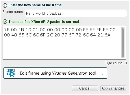
The frame you need looks like this:

This selects the Transmit request frame type (called ZigBee Transmit Request in the product manual). Most of the other parameters are fine at their defaults. Under 64-bit dest. address, enter 00 00 00 00 00 00 FF FF. This is the same broadcast address you configured in DH and DL before. When using API mode, these configuration values are unused; instead, the target address is specified for each outgoing frame individually.
Under RF Data, you can enter the actual message data to be sent.
After confirming with Ok, XCTU now shows the raw bytes of your Hello, world! frame. If you look closely, you can discover the 0x7e start byte, 0x001b as the frame length, 0x10 as the frame type, and the destination addresses:
Click on Apply changes to make the frame show up in the Send frames list. To actually send it to the router module, select it and click on Send selected frame to the right.
Doing this immediately makes two frames show up in the Frames log. The first is the Transmit Request frame sent to the module, followed by a Transmit Status reply. Clicking the frames shows their details to the right. If everything went right, the status frame will show a Delivery status of 00 (Success), indicating that the frame was successfully sent.
Now, head back to the serial monitor that shows the output from your Arduino. This should show the "Hello, world!" message you transmitted:
Starting....
48 65 6C 6C 6F 2C 20 57  Hello, W
6F 72 6C 64 21           orld!
As you can see, you can exchange data between nodes running in AT and API mode just fine; each will just output the received data to the serial port in its own mode. You could try sending a bit of data back from the Arduino to the coordinator as well, to see how that shows up in XCTU.
To complete the transition to API mode, you should switch over the second XBee module, too. For this, plug it into the XBee Explorer module temporarily to replace the firmware if needed and set AP=2.
Then plug the second XBee module back into the Arduino shield and the first one back into the Explorer. If you use XCTU as before to let the first module send the "Hello, World!" message again, the Arduino serial monitor output will look different from before:
Starting....
7E 00 19 90 00 13 A2 00  ~.......
40 D8 5F 9D 00 00 02 48  @._....H
65 6C 6C 6F 2C 20 57 6F  ello, Wo
72 6C 64 21 3B           rld!;
Instead of printing just the message, a full API frame is printed. The message is contained inside, but also the API frame type (0x90), sender address (0x0013A20040D85F9D), message length (0x0019), and so on. Check out the section on API operation in the product manual to figure out exactly what each byte means.
If you try typing some data into the Arduino serial monitor now, you will see that this data no longer shows up in XCTU like before. The XBee module expects to receive a correct binary API frame, which is unlikely to happen if you just type some letters. In the next chapter, you will see how to use an Arduino library to properly format these API frames.
To start sending data between your XBee modules, they all have to be joined to the same network first. In the previous examples, you have used a single coordinator and router, which together have automatically formed a network. In this section, you will learn a bit more about how these networks are formed and how addressing works.
The ZigBee protocol defines three different device types: coordinator, router, and end device. These are explained next:
A coordinator starts a network and allows other devices to join it. It otherwise acts as a normal router. Each network must have exactly one coordinator.
A router joins an existing network and will forward (route) packets on behalf of other members in the network, creating a mesh network. However, to maintain this routing functionality, routers cannot enter sleep mode and should usually be mains-powered.
An end device is more limited: it cannot do routing itself, instead relying on a router (or the coordinator) to route its messages to their destination. Unlike routers, end devices can sleep to save power.
A typical network might look like this:
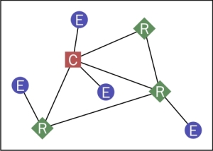
Note that the coordinator and routers can talk to each other (when they are close enough), but each end device can only talk to a single router (or the coordinator).
In the first chapters, you will use a single coordinator and one or more routers. In Chapter 6, Finishing Touches, end devices will be discussed in more detail.
In ZigBee, a network is identified by a PAN (Personal Area Network) identifier. When a coordinator is first started with its default settings, it will automatically start a new, unencrypted network by selecting a random PAN ID and a random channel. When a router or end device module starts, it will start scanning all channels for existing networks that allow new modules to join, select one, and join it. In the default configuration, coordinators and routers allow new devices to join the network without restriction.
There are a few related read-only configuration values supported, shown under the Networking category in XCTU:
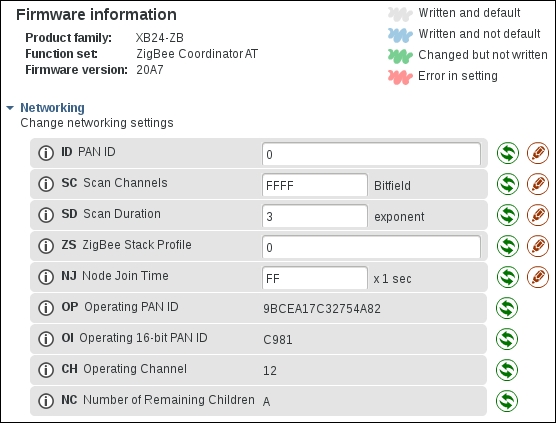
In the preceding screenshot, you can see the OP value. This is the Operating PAN ID: the PAN ID of the network created by the coordinator (or, on a router or end device, the PAN ID of the network successfully joined). The CH Operating Channel value shows the channel number selected by the coordinator (you might need to click on the Refresh button at the top to see the most recent values here).
Note that there is a second operating PAN ID here: OI. OP is a 64-bit long version, which is used in scan requests, beacons, and network joining, but OI is a 16-bit short version, which is used in most packets to save transmission time. If two different networks happen to have selected the same 16-bit PAN ID, the network can detect this and the conflict can be resolved by switching to a new 16-bit PAN ID. The 64-bit PAN ID will never change (unless of course the coordinator leaves the network, starts a new one, and ID is not set).
Also note the ID configuration value. This allows preconfiguring the 64-bit PAN ID on your modules by using a non-zero value. On a coordinator, this means the started network gets this 64-bit PAN ID. On routers and end devices, this means that the module will only join networks with a matching PAN ID and will ignore all others. Preconfiguring a PAN ID can help to prevent unexpected behavior (consider the case where your neighbor is also running a ZigBee network, and your nodes are joining his network instead of yours).
Go ahead and select some random 64-bit number for your network. This can be some easy to remember number, or whatever you like (unlike encryption keys, there is no security benefit of having a true random number here). Configure this number in the ID configuration value on both nodes. Changing the ID value on your modules will automatically cause them to leave their current network and create (or try to join) a new network.
You will see that, after this (and refreshing the configuration values in XCTU), the OP value (Operating 64-bit PAN ID) is set to the value you configured, but the OI value (Operating 16-bit PAN ID) is now different from before.
In addition to a PAN ID for the entire network, each module also has two addresses of its own. Using these addresses, modules will only receive data that is intended for them, and they can identify the sender of any data they receive.
The two different addresses for each module are:
A 64-bit extended address. This address is preconfigured in all XBee modules in the factory and can never be changed. These addresses are also called EUI-64 (Extended Unique Identifier). These identifiers are distributed by the IEEE, ensuring that every one of them is guaranteed to be globally unique (similar to MAC addresses in Ethernet adapters).
The 64-bit address of your XBee modules can be found by looking at the
SHandSLconfiguration values (which contain the upper and lower 32 bits of the address respectively), and is also printed on a sticker on the module itself (16 hexadecimal digits).A 16-bit short address. This address is used in normal communications and is assigned to a module when it joins the network. Normally, this address does not change until the module leaves the network again, but there is a chance that two modules could end up with the same short address, in which case both modules will get a new short address assigned automatically.
The coordinator always gets the
0x0000short address, while0xfffeis reserved for specifying an unknown address (this is usually used when the 64-bit address is known, but not the 16-bit address).The short address assigned to a module can be found by looking at the
MYconfiguration value.
To verify that all devices have been connected to the same network properly, or to find out more about how they are connected, you can use the network scanning feature in XCTU. This feature can be accessed in two ways. The most extensive one is by switching to the Network working mode at the top right:

Start a network scan using the Scan the radio module network button:

Alternatively, you can also directly click on the Discover radio nodes button next to a connected module in the list on the left. The former method shows more details about the network, such as a graph containing links, and shows all devices found. The latter method shows detected nodes in a list and only shows XBee modules.
To help identify nodes, the NI (Node Identifier) configuration value in the Addressing section can be used. This is just a human-readable name for this XBee module, which can help you tell them apart (though it is not shown in the network scan with the 6.2.0 version of XCTU, unfortunately).
In addition to discovering remote devices, you can also configure any remote XBee modules, just as if you are connected directly to them. To do so, double-click the device in the graph, or select it in the discovery list, and click on Add selected devices. Go ahead and explore these XCTU features; they might come in handy later.
Some XBee adapters or shields have a commissioning button, which can be used for some limited interaction with the module (such as briefly allowing new devices to join the network or doing a factory reset—see the product manual for details). Such a button simply connects to the AD0/DIO0 pin on one side and GND on the other, shorting them together when the button is pressed. If your setup does not have a button, it is easy to add one, or simply use a jumper wire to briefly make the connection to emulate a button press. Also, note that some adapters have a reset button (to reset the XBee and/or Arduino), so be sure to check what kind of button you have.
More commonly, adapters and shields have a LED connected to the XBee Associate/DIO5 pin (the associate LED) and/or the RSSI/DIO10 pin (the RSSI LED). The associate LED is lit continuously when a device is not joined to a network, but slowly blinks when the XBee module is successfully joined. It can also be used for more advanced diagnostics together with the commissioning button; see the product manual for details. The RSSI LED indicates the signal strength of the most recently received signal (the better the signal, the brighter the LED).
Both LEDs and the commissioning button can be disabled through the XBee configuration (to save power, or allow reusing the pin for a different purpose), but are enabled by default (though there will not always be a button or LED connected, of course).
Using wireless communication in your project is very convenient, but it also opens up the possibility of others sniffing your data, or even sending packets into your network to influence your project. For this reason, securing your network with proper encryption methods is an important step that is best taken right away (since it is easy to keep postponing it otherwise).
Fortunately, the XBee modules make securing your network easy and handle all the details automatically. There are a few concepts you need to understand, though.
When you enable security in your XBee module (by setting the EE configuration value to 1), most packets being sent will be encrypted (preventing others from reading the messages) and protected by a message integrity code (preventing others from inserting messages into your network). Special network-management packets (such as beacons, join requests, and so on) are not encrypted, nor are the lowest level packet headers, but the actual data you send is always secured.
This encryption happens using a secret key, called the network key (NK). All members of the network must know this key to allow sending and receiving messages. This network key can be configured on the coordinator by setting the NK configuration value. The default value of 0 causes the coordinator to select a random key when it creates a network, which should be sufficient in most cases.
When a module joins the network, it automatically receives the network key from the so-called trust center. The trust center is responsible for distributing network keys throughout the network when a node joins, or when the key is changed.
In XBee networks, the trust center always runs inside the coordinator, but the ZigBee protocol itself makes provision for running the trust center in another module as well. The ZigBee specification also allows preconfiguring the network key on all nodes, but the XBee firmware does not currently support this.
By default (with the KY configuration value set to its default of 0), the trust center sends the network key to joining nodes without using any encryption. This obviously poses a security risk: if someone can spy on your network traffic while your modules are joining the network, they can see your network key. Even more, an attacker could simply have his own module join the network and the network key would be sent to him, unencrypted.
To reduce this risk, you can configure your network to not allow new nodes to join normally, and only enable joining briefly when you have a new node to add. The network will still be vulnerable during these brief periods, but if the network is not compromised while joining is enabled, it will remain secure while joining is disabled. Refer to the Disabling network joining section for more info on how to disable joining.
To further secure the network and avoid having to send the network key unencrypted, ZigBee defines a second key, called the trust center link key. This key is manually configured in each module (using the KY configuration value) before it creates or joins the network. The trust center then uses this key to encrypt the network key when it is sent to new nodes joining the network. Eavesdroppers, not knowing the trust center link key, will not be able to decrypt the network key and so cannot read any of your data.
On XBee modules, there is a single trust center link key that must be known to all joining modules. The ZigBee protocol also allows for using a different trust center link key for each module, which would require more extensive configuration, but this is not supported by the current XBee ZB firmware.
Note
There is a third kind of key in the ZigBee protocol: an application link key. One of these keys can exist for every pair of modules in the network and allows additional end-to-end encryption (on top of the existing network encryption). This encryption is referred to as APS encryption in the XBee documentation and allows two modules to privately communicate, without allowing intermediate routers or other modules that are joined into the network to decrypt their messages.
Currently, the XBee firmware does not support these application link keys, so they will not be discussed any further.
It turns out there is a bit of a discrepancy between the XBee documentation and the ZigBee protocol specification around the concept of the trust center.
According to the ZigBee specification, a trust center is always needed to distribute the network key to newly joining nodes (unless the network key is already preconfigured on all nodes, which the XBee modules do not currently support). Additionally, the trust center can be used to distribute application keys or propagate a network key change throughout the entire network.
In the XBee documentation, distributing the network key to newly joining nodes is assumed to be done by the coordinator, even if the trust center is not enabled (controlled through the EO configuration value). Enabling the trust center seems to be needed only to allow propagating network key changes.
When selecting a random key, be sure to always select a full-length key. It is possible to enter a shorter key in the KY and NK configuration values and a lot of the examples in the XBee documentation also do this. However, if you enter, for example, ABCD as a key, it will be prepended with zeroes, so the actual key will end up being 0000000000000000000000000000ABCD. This severely limits the security—a four-digit key like this can be brute-forced in a matter of seconds using a regular computer.
A strong key should be properly random and be 32 (hexadecimal) digits long (which is 16 bytes or 128 bits). Keys such as these are effectively impossible to crack using brute force, even when using current supercomputers.
Now that you understand how security works in a ZigBee network, you can go ahead and restart your network with security enabled. To enable optimal security using a trust center link key, make the following configuration changes to both the coordinator and the router node (in either order):
Configure
EE=1Configure
KY(the trust center link key) to a randomly selected key. All modules should use the same key here.
For example:
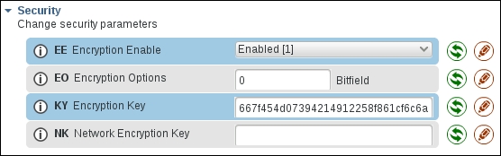
Note that the KY value can only be set, never read back, so be sure to store the key you set somewhere to allow adding new nodes to your network later.
Changing these values will automatically cause the modules to leave the current network and create a new network (coordinator) or find a new network to join (router).
After a few seconds, the new network should be formed. You can again transfer your Hello, world! message, but in a secure way this time.
By default, XBee modules allow new modules to join the network at any time. If you configured a trust center link key, joining is of course limited to nodes that know this secret key, preventing unauthorized access to your network.
However, as an additional layer of security (or, when not using a trust center link key, the primary layer), you can also disable all join attempts after you started your network and joined your devices. You can briefly re-enable joining later when you intend to add a new device to your network.
When a device wants to join a network, it searches for an existing router (or coordinator) that allows joining. Whether this is allowed depends on the NJ configuration value:
When
NJis0, joining is disabledWhen
NJis0xff, joining is enabledWhen a router joins a network, and its
NJvalue is not0or0xff, the router allows joining forNJsecondsWhen the
NJparameter is changed, joining is again enabled for that many secondsWhen the commissioning button is pressed twice quickly, joining is enabled for one minute
The NJ value is not a global value for the entire network, but each node has its own value and can decide on its own whether to allow new nodes to join. Even if the coordinator has joining disabled, the trust center will still send keys to nodes that joined through another router.
In general, it is a good idea to set NJ=0 on all modules by default, and then change the value on a nearby router or the coordinator (or use the commissioning button) whenever you need to add a node to the network.
Note that, for end devices, there is also a special rejoin procedure; refer to Chapter 6, Finishing Touches and the product manual for more information about this.
The ZigBee network structure used by the XBee ZB modules is the most complex of all the XBee modules discussed in this book. The other modules do not require having a central coordinator or going through a join procedure, but instead rely on manually assigning a 16-bit network identifier (ID) and operating channel (CH) on all nodes (except XBee-PRO 868, which only has one channel available). Security is also simpler: every node has the network key (KY) manually configured. There is no key distribution mechanism.
For the XBee 802.15.4 family, this applies in the default configuration, but there is a second mode where a simple join procedure can allow nodes to automatically detect the right channel and/or network identifier to use (the network key must still be manually configured).
DigiMesh and XBee 868 networks use only a 64-bit address for each node and all transmissions. All nodes in an 802.15.4 network have a 64-bit address and can optionally have a manually assigned 16-bit address too (MY). Sending a packet in a 802.15.4 network uses either a 64-bit or 16-bit destination address (but, if you use a 64-bit address, the full address is transmitted over the air; there is no mechanism to look up the 16-bit address and use that in packets as with ZigBee).
XBee 802.15.4 and XBee-PRO 868 networks do not have any mesh capabilities, so you can only send messages between nodes that can directly hear each other. DigiMesh networks do support meshing similar to ZigBee.
Some other families also have device roles such as coordinator or end device, though the difference between them is less than in ZigBee networks. See the relevant product manual for details.
If you followed the preceding examples, you should have configured the following values on all your XBee modules:
AP=2to enable API mode with escapingID=<your PAN ID>to prevent joining other networksEE=1to enable securityKY=<random 32-digit key>to prevent others without this key from joining the networkNJ=0to prevent new nodes from joining
The changes to DH and DL were only needed for the AT mode examples and are no longer relevant in API mode.
In this chapter, you have learned about some wireless terminology and available hardware, and sent some bytes over the air. Your XBee network is even secured against eavesdropping. You have already used an Arduino as a simple forwarder of data, but it is time to put your Arduinos in control of the XBee modules and get them talking to each other! The next chapter will show how to connect your XBee modules to your Arduino and how to exchange some simple sensor data.


