


The basis for this book is the Arduino platform, which refers to three different things: software, hardware, and the Arduino philosophy. The hardware is the Arduino board, and there are multiple versions available for different needs. In this book, we will be focusing on Arduino boards that were made with wearables in mind. The software used to program the boards is also known as the Arduino IDE. IDE stands for Integrated Development Environment, which are programs used to write programs in programming code. The programs written for the board are known as sketches, because the idea aids how to write programs and works similar to a sketchpad. If you have an IDE, you can quickly try it out in code. This is also a part of the Arduino philosophy. Arduino is based on the open source philosophy, which also reflects on how we learn about Arduino. Arduino has a large community, and there are tons of projects to learn from.
First, we have the Arduino hardware, which we will use to build all the examples in this book along with different additional electronic components. When the Arduino projects started back in 2005, there was only one piece of headwear to speak of, which was the serial Arduino board. Since then, there have been several iterations of this board, and it has inspired new designs of the Arduino hardware to fit different needs. If you are familiar with Arduino for a while, you probably started out with the standard Arduino board. Today, there are different Arduino boards that fit different needs, and there are countless clones available for specific purposes. In this book, we will be using different specialized Arduino boards such as the FLORA board and Spark core board.
The Arduino software that is Arduino IDE is what we will use to program our projects. The IDE is the software used to write programs for the hardware. Once a program is compiled in the IDE, it will upload it to the Arduino board, and the processor on the board will do whatever your program says. Arduino programs are also known as sketches. The name sketches is borrowed from another open source project and software called Processing. Processing was developed as a tool for digital artists, where the idea was to use Processing as a digital sketchpad.
The idea behind sketches and other aspects of Arduino is what we call the Arduino philosophy, and this is the third thing that makes Arduino. Arduino is based on open source, which is a type of licensing model where you are free to develop you own designs based on the original Arduino board. This is one of the reasons why you can find so many different models and clones of the Arduino boards. Open source is also a philosophy that allows ideas and knowledge to be shared freely. The Arduino community has grown strong, and there are many great resources to be found, and Arduino friends to be made.
The only problem may be where to start? Books like this one are good for getting you started or developing skills further. Each chapter in this book is based on a project that will take you from the start, all the way to a finished "prototype". I call all the project prototypes because these are not finished products. The goal of this book is also for you to develop these projects further, once you have completed the chapter. As your knowledge progresses, you can develop new sketches to run on you prototypes, develop new functions, or change the physical appearance to fit your needs and preferences.
In this chapter, you will have a look at:
Installing the IDE
Working with the IDE and writing sketches
The FLORA board layout
Connecting the FLORA board to the computer
Controlling and connecting LEDs to the FLORA board
This book is all about wearables, which are defined as computational devices that are worn on the body. A computational device is something that can make calculations of any sort. Some consider mechanical clocks to be the first computers, since they make calculations on time. According to this definition, wearables have been around for centuries, if you think about it. Pocket watches were invented in the 16th century, and a watch is basically as small device that calculates time. Glasses are also an example of wearable technology that can be worn on your head, which have also been around for a long time. Even if glasses do not fit our more specified definition of wearables, they serve as a good example of how humans have modified materials and adapted their bodies to gain new functionality. If we are cold, we dress in clothing to keep us warm, if we break a leg, we use crutches to get around, or even if an organ fails, we can implant a device that replicates their functionality. Humans have a long tradition of developing technology to extend the functionality of the human body.
With the development of technology for the army, health care, and professional sport, wearables have a long tradition. But in recent years, more and more devices have been developed for the consumer market. Today, we have smart watches, smart glasses, and different types of smart clothing.
In this book, we will carry on this ancient tradition and develop some wearable projects for you to learn about electronics and programming. Some of these projects are just for fun and some have a specific application. The knowledge presented in all the chapters of this book progresses from the chapter before it. We will start off slow, and the chapters will gradually become more complex both in terms of hardware and software. If you are already familiar with Arduino, you can pick any project and get started. If you find it too hard, you can always go back and take a look at the chapter that precedes it. If you're completely new to Arduino, continue reading this chapter as we will go through the installation process of the Arduino IDE and how to get started with programming.
The projects in this book will be based on different boards made by the company Adafruit. Later in this chapter, we will take a look at one of these boards, called the FLORA, and explain the different parts. These boards come with a modified version of the Arduino IDE, which we will be using in the chapter. The Adafruit IDE looks exactly the same as the Arduino IDE. The FLORA board, for example, is based on the same microprocessor as the Arduino Leonardo board and can be used with the standard Arduino IDE but programmed using the Leonardo board option. With the use of the Adafruit IDE the FLORA board is properly named. In this book, we will use two other models called the Gemma and Trinket boards, which are based on a microprocessor that is different from the standard Arduino boards. The Adafruit version of the IDE comes preloaded with the necessary libraries for programming these boards, so there is no need to install them separately.
For downloading and instructions on installing the IDE, head over to the Adafruit website and follow the steps on the website:
https://learn.adafruit.com/getting-started-with-flora/download-software
Make sure to download the software corresponding to your operating system. The process for installing the software depends on your operating system. These instructions may change over time and may be different for different versions of the operating system. The installation is a very straightforward process if you are working with OS X. On Windows, you will need to install some additional USB drivers. The process for installing on Linux depends on which distribution you are using. For the latest instructions, take a look at the Arduino website for the different operating systems.
On the following website, you can find the original Arduino IDE if you need it in the future. In this book, you will be fine sticking with the Adafruit version of the IDE, since the most common original Arduino boards are also supported. The following is the link for downloading the Arduino software: https://www.arduino.cc/en/Main/Software.
The IDE is where we will be doing all of our programming. The first time you open up the IDE, it should look like Figure 1.1:
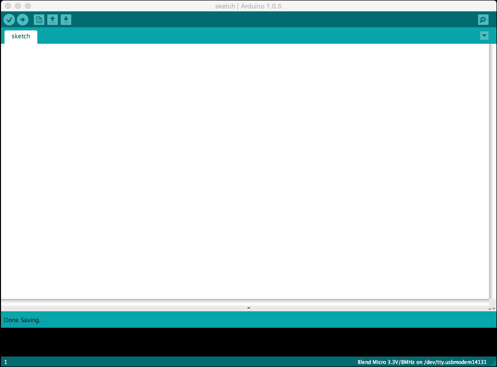
Figure 1.1: The Arduino IDE
The main white area of the IDE is blank when you open a new sketch, and this is the area of the IDE where we will write our code later on. First, we need to get familiar with the functionality of the IDE.
At the top left of the IDE, you will find five buttons. The first one, which looks like a check sign, is the compile button. When you press this button, the IDE will try to compile the code in your sketch, and if it succeeds, you will get a message in the black window at the bottom of you IDE that should look similar to this:
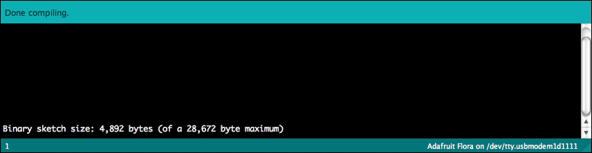
Figure 1.2: The compile message window
When writing code in an IDE, we will be using what is known as a third-level programming language. The problem with microprocessors on Arduino boards is that they are very hard to communicate with using their native language, and this is why third-level languages have been developed with human readable commands. The code you will see later needs to be translated into code that the Arduino board understands, and this is what is done when we compile the code. The compile button also makes a logical check of your code so that it does not contain any errors. If you have any errors, the text in the black box in the IDE will appear in red, indicating the line of code that is wrong by highlighting it in yellow. Don't worry about errors. They are usually misspelling errors and they happen a lot even to the most experienced programmers. One of the error messages can be seen in the following screenshot:

Figure 1.3: Error message in the compile window
Adjacent to the compile button, you will find the Upload button. Once this button is pressed, it does the same thing as the compile button, and if your sketch is free from errors, it will send the code from your computer to the board:

Figure 1.4: The quick buttons
The next three buttons are quick buttons for opening a new sketch, opening an old sketch, or saving your sketch. Make sure to save your sketches once in a while when working on them. If something happens and the IDE closes unexpectedly, it does not autosave, so manually saving once in a while is always a good idea.
At the far right of the IDE you will find a button that looks like a magnifying glass. This is used to open the Serial monitor. This button will open up a new window that lets you see the communication form from, and to, the computer and the board. This can be useful for many things, which we will have a closer look at in Chapter 2, Working with Sensors.
At the top of the screen you will find a classic application menu, which may look a bit different depending on your operating system, but will follow the same structure. Under File, you will find the menu for opening your previous sketches and different example sketches that come with the IDE, as shown in Figure 1.5. Under Edit, you will find different options and quick commands for editing your code. In Sketch, you can find the same functions as in the buttons in the IDE window:
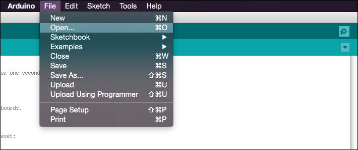
Figure 1.5: The File menu
Under Tools, you will find two menus that are very important to keep track of when uploading sketches to your board. Navigate to Tools | Board and you will find many different types of Arduino boards. In this menu, you will need to select the type of board you are working with. Under Tools | Serial port, you will need to select the USB port which you have connected to your board. Depending on your operating system, the port will be named differently. In Windows, they are named COM*. On OS X, they are named /dev/tty.****:
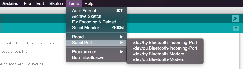
Figure 1.6: The Tools menu
Since there may be other things inside your computer also connected to a port, these will also show up in the list. The easiest way to figure out which port is connected to your board is to:
Plug you board in to your computer using a USB cable.
Then check the Serial port list and remember which port is occupied.
Unplug the board and check the list again.
The board missing in the list is the port where your board is connected. Plug your board back in and select it in the list. All Arduino boards connected to you computer will be given a new number.
As I mentioned earlier, we will not be using the standard Uno Arduino boards in this book, which is the board most people think of when they hear Arduino board. Most Arduino variations and clones use the same microprocessors as the standard Arduino boards, and it is the microprocessors that are the heart of the board. As long as they use the same microprocessors, they can be programmed as normal by selecting the corresponding standard Arduino board in the Tools menu. In our case, we will be using a modified version of the Arduino IDE, which features the types of boards we will be using in this book. What sets other boards apart from the standard Uno Arduino boards is usually the form factor of the board and pin layout. In this book, we will be using a board called the FLORA. This board was created with wearables in mind. The FLORA is based on the same chip used in the Arduino Leonardo board, but uses a much smaller form factor and has been made round to ease the use in a wearable context. You can complete all the projects using most Arduino boards and clones, but remember that the code and construction of the project may need some modifying.
In the following Figure 1.7 you will find the FLORA board:
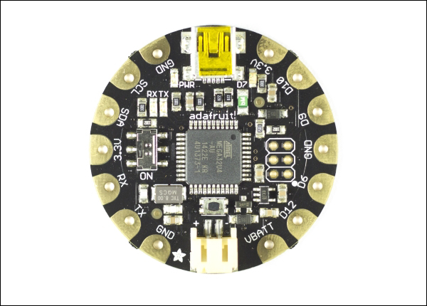
Figure 1.7: The FLORA board
The biggest difference to normal Arduino boards besides the form factor is the number of pins available. The pins are the copper-coated areas at the edge of the FLORA. The form factor of the pins on FLORA boards is also a bit different from other Arduino boards. In this case, the pin holes and soldering pads are made bigger on FLORA boards so they can be easily sewn into garments, which is common when making wearable projects. The larger pins also make it easier to prototype with alligator clips, which we will be using later on in this chapter as shown in Figure 1.10. The pins available on the FLORA are as follows, starting from the right of the USB connector, which is located at the top of the board in the preceding Figure 1.7:
The pins available on the FLORA are as follows, starting from the right of the USB connector, which is located at the top of the board in Figure 1.7:
3.3V: Regulated 3.3 volt output at a 100mA max
D10: Is both a digital pin 10 and an analog pin 10 with PWM
D9: Is both a digital pin 9 and an analog pin 9 with PWM
GND: Ground pin
D6: Is both a digital pin 6 and an analog pin 7 with PWM
D12: Is both a digital pin 12 and an analog pin 11
VBATT: Raw battery voltage, can be used for as battery power output
GND: Ground pin
TX: Transmission communication pin or digital pin 1
RX: Receive communication pin or digital pin 0
3.3V: Regulated 3.3 volt output at a 100mA max
SDA: Communication pin or digital pin 2
SCL: Clock pin or digital pin 3 with PWM
As you can see, most of the pins have more than one function. The most interesting pins are the D* pins. These are the pins we will use to connect to other components. These pins can either be a digital pin or an analog pin. Digital pins operate only in 1 or 0, which mean that they can be only On or Off. You can receive information on these pins, but again, this is only in terms of on or off.
The pins marked PWM have a special function, which is called Pulse Width Modulation. On these pins, we can control the output voltage level. The analog pins, however, can handle information in the range from 0 to 1023. As we introduce analog sensors in Chapter 2, Working with Sensors, we will look into the differences between them in more detail.
The 3.3V pins are used to power any components connected to the board. In this case, an electronic circuit needs to be completed, and that's why there are two GND pins. In order to make an electronic circuit, power always needs to go back to where it came from. For example, if you want to power a motor, you need power from a power source connected via a cable, with another cable directing the power back to the power source, or the motor will not spin.
TX, RX, SDA, and SCL are pins used for communication, which we will have a look at later on in the book in the chapters dealing with more complex sensors. The VBATT pin can be used to output the same voltage as your power source, which you connect to the connector located at the bottom of the FLORA board shown in Figure 1.7.
In Figure 1.8 you will find the other board types we will be using in this book:
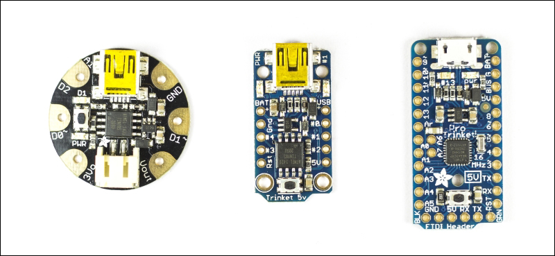
Figure 1.8: The Gemma, Trinket and Trinket pro board
In Figure 1.8, the first one from the left is the Gemma board. In the middle, you will find the Trinket board, and to the right, you have the Trinket pro board. Both the Gemma and Trinket board are based on the ATtiny85 microprocessor, which is a much smaller and cheaper processor, but comes with limitations. These boards only have three programmable pins, but what they lack in functionality, the make up for in size. The difference between the Gemma and Trinket board is the form factor, but the Trinket board also lacks a battery connector. The Trinket Pro board runs on an Atmega328 chip, which is the same chip used on the standard Arduino board to handle the USB communication.
This chip has 20 programmable pins, but also lacks a battery connector. The reason for using different types of boards in this book is that different projects require different functionalities, and in some cases, space for adding components will be limited. Don't worry though, since all of them can be programmed in the same way.
In order to make sure that you have installed your IDE correctly and to ensure your board is working, we need to connect it to your computer using a USB to USB micro cable, as show in Figure 1.9:
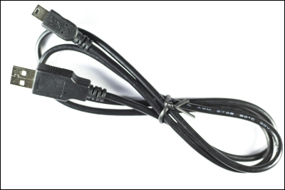
Figure 1.9: USB to USB micro cable
The small connector of the cable connects to your board, and the larger connector connects to your computer. As long as your board is connected to your computer, the USB port on the computer will power your board. In Chapter 3, Bike Gloves, we will take a closer look at how to power your board using batteries.
Once your board is connected to the computer, open up your IDE and enter the following code. Follow the basic structure of writing sketches:
The setup you make is the first segment of code that runs when the board is powered up.
Then, add the loop function, which is the second segment of the code that runs, and will keep on looping until the board is powered off:
int led = 7;

void setup()
{
pinMode(led, OUTPUT);
}

void loop()
{
digitalWrite(led, HIGH);
delay(1000);
digitalWrite(led, LOW);
delay(1000);
}
The first line of code declares pin number 7 as an integer and gives it the name LED. An integer is a data type, and declaring the variable using the name int allows you to store whole numbers in memory. On the FLORA board, there is a small on-board LED connected to the digital pin 7. The next part is void setup(), which is one of the functions that always needs to be in your sketch in order for it to compile. All functions use curly brackets to indicate where the function starts and ends. The { bracket is used for the start, and } the bracket is used to indicated the end of the function. In void setup(), we have declared the mode of the pin we are using. All digital pins can be used as either an input or an output. An input is used for reading the state of anything connected to it, and output is used to control anything connected to the pin. In this case, we are using pin 7, which is connected to the on-board LED. In order to control this pin we need declared it as an output.
Tip
If you are using a different board, remember to change the pin number in your code. On most other Arduino boards, the onboard LED is connected to pin 13.
The void loop() function is where the magic happens. This is where we put the actual commands that operate the pins on the board. In the preceding code, the first thing we do is turn the led pin HIGH by using the digitalWrite()command. The digitalWrite() function is a built-in function that takes two parameters. The first is the number of the pin, in this case, we put in the variable led that has the value 7. The second parameter is the state of the pin, and we can use the HIGH or LOW shortcuts to turn the pin on or off, respectively.
Then, we make a pause in the program using the delay() command. The delay command takes one parameter, which is the number of milliseconds you want to pause your program for. After this, we use the same command as before to control the state of the pin, but this time we turn it LOW, which is the same as turning the pin off. Then we wait for an additional 1000 milliseconds. Once the sketch reaches the end of the loop function, the sketch will start over from the start of the same function and keep on looping until a new sketch is uploaded. The reset button is pressed on the FLORA board, or until the power is disconnected.
Now that we have the sketch ready, you can press the upload button. If everything goes as planned, the on-board LED should start to blink with a 1 second delay. The sketch you have uploaded will stay on the board even if the board is powered off, until you upload a new sketch that overwrites the old one. If you run into problems with uploading the code, remember to perform the following steps:
Check your code for errors or misspelling
Check your connections and USB cable
Make sure you have the right board type selected
Make sure your have the right USB port selected
Now that we know that your IDE and board are working, we will have a look at some more code. Programming with Arduino is a fairly straightforward process, but as with any other skill, it takes some practice. You should never feel stupid if you don't understand straightaway or if you can't get something to work as it should. This is a part of the process we call prototyping. When you prototype something, you may have a clear idea of what you want to do, but not a clear plan of how to achieve this. A big part of prototyping is the process of trial and error. If you try something and it does not work, then you try something different. A common misconception is that electronics break easily. It is true that components can break if connected the wrong way, but even breaking stuff can be helpful in the process of understanding how they work. However, it is very hard to break anything by code. Again, it is possible to break the microprocessor in most Arduino boards by uploading faulty code to them, but the IDE makes this nearly impossible since it always checks your code for errors before uploading it to the board. Microprocessors are logical in the strictest sense.
When learning to program, the most important part is to learn how to debug. Debugging is simply the process of finding where the problem is. Compile errors are the most obvious, since the IDE will let you know that your sketch contains an error somewhere. However, the IDE can only check for semantic errors and it does not know what you are trying to achieve. Your sketch might compile, but it still does not do what you want it to do. The deeper your understanding of the different commands, the faster you will become in the debugging process. In this book, I will explain the different commands as they are used in the chapters, but even if we use a lot of them, we will not cover all possible commands. If you want to learn more about all the possible commands, the Arduino website has a reference list in which you can find them (http://arduino.cc/en/Reference/HomePage). This book is aimed at readers who have some experience with programming for Arduino, and it does not include an introduction to programming. With this said, you should not feel excluded if you don't know how to program, since it should be possible to follow all the projects without a deeper understanding of programming. By following the instructions and code in this book, you should be able to create your own working version of all the projects. The following sketches are examples to get you going, which includes some of the basic functions and commands.
Tip
Note that all code that is proceeded by the use of // or /*……*/ are comments. The // (comment character) hides the line of code from the compiler, and will not be a part of the sketch. The /*……*/ (comment character) hides comments that are spread over multiple lines, where anything written in between /* and */ will be hidden from the compiler. It is good programming practice to add comments to document your code.
Now that we've tried a really simple example with the board by itself, it's time to add some extra components:
FLORA board
USB to USB micro cable
Two alligator clips
PCB mounted LED
Tip
Downloading the example code
You can download the example code files from your account at http://www.packtpub.com for all the Packt Publishing books you have purchased. If you purchased this book elsewhere, you can visit http://www.packtpub.com/support and register to have the files e-mailed directly to you.
In this sketch example, we will use an external LED, but if you want, you can stick with the on-board LED on the FLORA board. The LED used in following Figure 1.10 is a special surface-mounted LED that is placed on a PCB. If you are using another LED, make sure to pair it with the right resistor. In the case of the custom LED found in Figure 1.6, the resistor is mounted on a PCB (printed circuit board). These LEDs are made with wearables in mind, and you can find them in most specialized electronic stores:
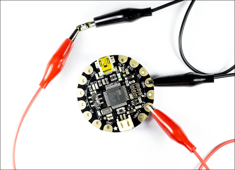
Figure 1.10. The LED connected to the board using alligator clips
To connect the LED to the board, we used alligator clips. Alligator clips are normal wires with metal clips at the end that are great for prototyping, and work especially well with wearable Arduino boards like the FLORA. LEDs have a positive and a negative side to them. In the case of the LED in Figure 1.10, these are marked on the PCB with a + sign for the positive and a - sign for the negative side. The positive side connects to pin D12 on the FLORA board, and to complete the circuit, the negative side connects to GND.
The following sketches show how to blink the LED at different speeds, using the for loops:
int led = 12; //declares a variable called led connected to pin 12

void setup() {
  pinMode(led, OUTPUT); //declares led as an output pin
}

void loop() {
//start looping until the counter is bigger then 5
  for(int i=0; i<5; i++){
    digitalWrite(led, HIGH); //turn the led on
    delay(1000); //wait for a bit
    digitalWrite(led, LOW); //turn the led off
    delay(1000); //wait some more
  }
//start looping until the counter is bigger then 5
  for(int j=0; j<5; j++){
    digitalWrite(led, HIGH); //turn the led on
    delay(500); //wait for a bit
    digitalWrite(led, LOW); //turn the led off
    delay(500); //wait some more
  }
//start looping until the counter is bigger then 5
  for(int k=0; k<5; k++){
    digitalWrite(led, HIGH); //turn the led on
    delay(100); //wait for a bit
    digitalWrite(led, LOW); //turn the led off
    delay(100); //wait some more
  }
}
In this sketch, we use three different for loops. In the for loop, a counter, end condition, and counter increment is declared. All the counters in this sketch start on 0, and as long as the counter is smaller than 5, the for loop will keep on looping. For every time the for loop makes a loop, the counter is increased by one. Inside the for loop, the LED is first turned on and then there is a delay. The delay time is the difference between the three for loops.
Then, the LED is turned off and there is a new delay. Once the first loop has met the end condition, the second loop takes over, and so on. The for loops are good if you know you want to do a certain thing a certain number of times.
As you can see in the preceding sketch, the procedure for turning the LED on and off is the same for all of the for loops. This is a perfect opportunity to introduce a function into your code. Functions help save memory space. In the case of the sketch we are working with, memory space will not become a problem since the sketch is very small. However, as you progress, sketches will become bigger and bigger, and memory space may become a problem. Depending on the board you are using, there is a limit to how big you can make you sketches. Optimizing your code helps save space, but is also good coding practice, since it gives you a better overview of your code:
int led = 12;

void setup() {
  pinMode(led, OUTPUT);
}

void loop() {
  for(int i=0; i<5; i++){
    blinkLed(1000); //call the function and add the delay time
  }
  for(int j=0; j<5; j++){
    blinkLed(500); //call the function and add the delay time
  }
  for(int k=0; k<5; k++){
    blinkLed(100); //call the function and add the delay time
  }
}

/*declares the function blinkLed and adds a parameter that needs to be included with the use of the function*/
void blinkLed(int delayTime){
digitalWrite(led, HIGH); //turn the led on
    delay(delayTime); //wait for a bit
    digitalWrite(led, LOW); //turn the led off
    delay(delayTime); //wait some more
}
The blinkLed function has been declared so it takes a parameter, which is delayTime. This variable is then used inside the function to set the speed of the blinking.
In this chapter, we have had a look at the different parts of the FLORA board and how to install the IDE. We also made some small sketches to work with the on-board LED. We made our first electronic circuit using an external LED.
In the next chapter, I will introduce you to some analog sensors that are suitable for working with wearable's. We will keep using LEDs as our output, to show how we can interact with the data gathered from the sensors, as well as how to control the intensity of the LED.
