Modeling a test area
The walls will be modeled using the same X, Y coordinate system as the poses. We'll start by making a drawing of test area C, but using coordinates:
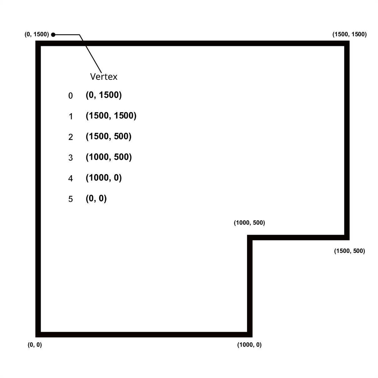
Figure 12.5 – The walls represented as edges
The preceding figure shows the walls or boundaries of our test area. Each corner has a coordinate written in it, a vertex or plural vertices.
You may not have a space large enough or the right shape. You can use a smaller or different shape under these conditions:
The space is approximately the same L shape, a rectangle with a corner cut out of it. Non-right angles make things significantly more complicated, and without the corner feature, all sides look the same to the robot.
You will need to take measurements in mm of the space, all corners, and translate those numbers here, in the walls list, and the boundary-checking conditions.
In the diagram, a numbered list of vertices is shown in the middle of the arena, starting from the vertex at index 0. We will use...